Thermal Process Technology - Skafte MedLab AB
Thermal Process Technology - Skafte MedLab AB
Thermal Process Technology - Skafte MedLab AB

You also want an ePaper? Increase the reach of your titles
YUMPU automatically turns print PDFs into web optimized ePapers that Google loves.
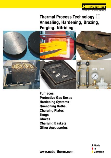
<strong>Thermal</strong> <strong>Process</strong> <strong>Technology</strong><br />
Annealing, Hardening, Brazing,<br />
Forging, Nitriding<br />
Furnaces<br />
Protective Gas Boxes<br />
Hardening Systems<br />
Quenching Baths<br />
Charging Plates<br />
Tongs<br />
Gloves<br />
Charging Baskets<br />
Other Accessories<br />
www.nabertherm.com<br />
Made<br />
in<br />
Germany
Made in Germany<br />
Nabertherm with 350 employees worldwide have been developing and producing industrial furnaces for many<br />
different applications for over 60 years. As a manufacturer, Nabertherm offers the widest and deepest range<br />
of furnaces worldwide. 150,000 satisfied customers in more than 100 countries offer proof of our commitment<br />
to excellent design, quality and cost efficiency. Short delivery times are ensured due to our complete inhouse<br />
production and our wide variety of standard furnaces.<br />
Setting Standards in Quality and Reliability<br />
Nabertherm does not only offer the widest range of standard furnaces. Professional engineering in combination<br />
with inhouse manufactoring provide for individual project planning and construction of tailor-made thermal process<br />
systems with material handling and charging systems. Complete thermal processes are realized by customized<br />
system solutions.<br />
Innovative Nabertherm control technology provides for precise control as well as full documentation and remote<br />
monitoring of your processes. Our engineers apply state-of-the-art technology to improve the temperature<br />
uniformity, energy efficiency, reliability and durability of our systems with the goal of enhancing your competitive<br />
edge.<br />
Global Sales and Service Network – Close to you<br />
Centralized engineering and manufacturing and decentralized sales and service define our strategy to live up to your<br />
needs. Long term sales and distribution partners in all important world markets ensure individual on-site customer<br />
service and consultation. There are various reference customers in your neighborhood who have similar furnaces or<br />
systems.<br />
Large Test Center for Customers<br />
What furnace is the right choice for this specific process? This question cannot<br />
always be answered easily. Therefore, we have set up our modern test center<br />
which is unique in respect to size and variety. A representative number of<br />
furnaces is available for tests for our customers.<br />
Customer Service and Spare Parts<br />
Our professional service engineers are available for you world-wide. Due to our<br />
complete inhouse production, we can despatch most spare parts from stock over<br />
night or produce with short delivery time.<br />
Experience in Many Fields of <strong>Thermal</strong> <strong>Process</strong>ing<br />
In addition to products for Heat Treatment, Nabertherm offers a wide range of standard furnaces and systems for<br />
many other thermal processing applications. The modular design of our products provides for customized solutions<br />
to your individual needs without expensive modifications.
Contents<br />
Page<br />
Annealing, Hardening, Carburizing, Boriding, Forging, Nitriding, Brazing<br />
Chamber Furnaces with Radiation Heating .............................................................................5<br />
Charging Plates, Hardening Boxes ..............................................................................6<br />
Neutral Annealing Coal, Carburizing Powder and Granulate .............................................7<br />
Nitriding Powder and Activator, Boriding Powder ...........................................................7<br />
Stainless Steel Heat Treating Foil to avoid Surface Reactions ....................................................8<br />
Annealing and Hardening Treating Foils ........................................................................8<br />
Accessory Equipment for <strong>Process</strong>ing Bags, Envelopes and Foils ......................................8<br />
Annealing Envelopes, Annealing Bags ..........................................................................9<br />
Protective Gas Operation<br />
Protective Gas Annealing Bag and Holder ................................................................... 10<br />
Protective Gas Boxes .............................................................................................. 11<br />
Protective Gas Boxes with Additional Vacuum Lid ........................................................ 1<br />
Vacuum Pump ........................................................................................................ 13<br />
Protective Gas Boxes with Hinged Lids....................................................................... 13<br />
Protective Gas Boxes with Hinged Lids which remain in the Furnace ............................... 14<br />
Protective Gas Systems ........................................................................................... 15<br />
Measuring Temperatures in Protective Gas Systems ..................................................... 16<br />
Tool Shop Hardening Systems ............................................................................................ 17<br />
SHS 41 Protective Gas Hardening System ............................................................................ 19<br />
Cooling Platforms ............................................................................................................. 0<br />
Quenching and Cleaning Baths ........................................................................................... 0<br />
Hardening Oil, Quench Water Additive, Detergent, Insulating Materials..................................... 1<br />
Draw Hook, Binding Wire, Hardening Tongs, Gloves ...............................................................<br />
Heat-Resistant Face Mask .................................................................................................<br />
Tempering, Solution Annealing, Artificial Aging, Soft Annealing, Brazing<br />
Chamber Furnaces with Air Circulation ................................................................................ 3<br />
Protective Gas Boxes .............................................................................................. 4<br />
Protective Gas Boxes with Vacuum Lid ....................................................................... 4<br />
Pit-Type Furnaces with Air Circulation .................................................................................. 5<br />
Charging Aid .......................................................................................................... 6<br />
Protective Gas Boxes .............................................................................................. 6<br />
Charging Baskets ................................................................................................... 7<br />
Salt Bath and Bath-Type Annealing, Tempering and Austempering<br />
Martempering Furnaces using Neutral Salt ........................................................................... 8<br />
Salt-Bath Furnaces using Neutral or Active Salt .................................................................... 9<br />
Charging Devices<br />
Charging Trolley ............................................................................................................... 30<br />
Charging Stacker ............................................................................................................. 30<br />
Hardness Tester ........................................................................................................................ 31<br />
Experience in using different Materials ..................................................................................... 3<br />
The Nabertherm Product Range ................................................................................................ 33<br />
Steel Selection .............................................................................................. 34<br />
3
4<br />
Overview of Heat Treatment<br />
<strong>Process</strong>es<br />
Quenching and Tempering<br />
Case Hardening<br />
Hardening<br />
Tempering<br />
Solution Annealing<br />
Aging<br />
Annealing<br />
Recovery Annealing<br />
Recrystallization Annealing<br />
Stress Relief Annealing<br />
Soft Annealing<br />
Normalizing<br />
<strong>Thermal</strong> Chemical Diffusion<br />
Without Subsequent Hardening:<br />
Oxidizing<br />
Powder Nitriding<br />
Powder Boriding<br />
with Subsequent Hardening:<br />
Carburizing<br />
As a manufacturer of electrically and gas heated furnaces for heat treatment, Nabertherm offers a wide range of<br />
accessory equipment and consumable materials required for heat treatment.<br />
The MHS 17 hardening system shown on page 17, featuring an oil and water bath as well as an air quenching<br />
system, is suitable for occasional applications. This system can be extened to a full-scale hardening shop using<br />
a minimum of space. The basis for annealing are the furnace models N 7/H - N 17/HR and for tempering, the<br />
circulation air furnace N 15/65 HA.<br />
Multitherm N 31/H - N 81 chamber furnaces as well as Multitherm N 30/45 - N 1 0/85 HA circulation air furnaces are<br />
suitable for hardening and tempering of medium-sized workpieces. In addition to oil and water baths, charging aids<br />
can also be supplied for these models. The semi-automated SHS 41 protective gas hardening system is suitable for<br />
annealing under protective gas and quenching in oil.<br />
For large-format workpieces we recommend furnaces N 161 - N 1491 and N 50/45 - N 500/85 HA. There are<br />
also charging aids available for these models. Quenching baths are custom manufactured and designed to fit the<br />
process.<br />
Protective gas boxes and bags can be used to prevent oxidation and decarburizng of the steel during heat<br />
treatment. These are flushed with protective gases such as argon, nitrogen or forming gas 95/5 and thus force the<br />
oxygen out of the containers. The systems required and their corresponding furnaces and boxes, are described in<br />
detail. If there is no protective gas available, workpieces can also be wrapped in annealing and hardening foils or<br />
packed in annealing envelopes. The foil used binds the enclosed oxygen. If used properly, clean, oxidation-free<br />
surfaces are achieved under protective gas as well as enclosed in foil.<br />
Annealing boxes and the required consumables are available for powder nitriding to obtain greater protection<br />
against corrosion, for carburizing of low alloy steels, for neutral atmosphere annealing in an oxygen-free atmosphere<br />
and for boriding.<br />
For the even quenching of workpieces and for bainitic hardening, Nabertherm supplies bath furnaces with neutral<br />
salt for temperatures up to 500 °C. Salt bath furnaces up to 750 °C and 1000 °C are available for heat treatment in<br />
active salt baths, for Tenifer nitriding, for carburizing and bright annealing.<br />
There are tongs, face protection, gloves and other equipment available for working at the hot furnace. We can<br />
supply a Rockwell hardness tester for testing hardness after treatment.<br />
The furnaces described in this catalog and the accessory equipment available allow many different heat treatment<br />
processes which otherwise are only possible using expensive furnace systems. This brochure offers customers the<br />
opportunity to assemble their own hardening shop to their own specifications and makes it easy to select required<br />
accessory equipment.<br />
Contact Nabertherm at any time for a detailed consultation.
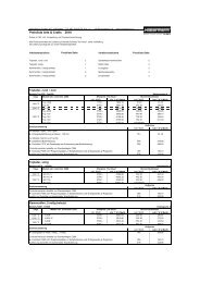
Chamber Furnaces with Radiation Heating<br />
N 7/H<br />
N 7/H - N 1491<br />
These universal chamber furnaces with radiation heating are designed for highly adverse conditions during heat<br />
treatment. They are ideally suited for tooling construction processes and in the hardening shop, such as annealing,<br />
hardening or preheating for forging. The use of various accessories allow these furnaces to be modified for your<br />
application.<br />
Standard Features, Table-Top Models N 7/H - N 17/HR<br />
� Compact, low-cost construction<br />
� Heating from floor and both side walls<br />
� Heating elements on support tubes ensure free heat radiation and a long service life<br />
� Low energy consumption due to multi-layer insulation<br />
� Casing made of sheets of textured stainless steel (non-corrosive design)<br />
� Exhaust air vent mounted on the side<br />
� Optimal temperature uniformity up to ΔT 0 K in accordance with DIN 1705 -1<br />
� Floor heating protected by heat conducting SiC tiles<br />
� Parallel swinging door which opens downward (protection against heat radiation)<br />
Standard Features N 31/H - N 61/H, like models N 7/H - N 17/HR, plus<br />
� Upper door area amored with stainless steel to avoid burn damage<br />
� Exhaust air vent in rear wall of furnace<br />
� Door movement cushioned by gas springs<br />
� Base included in delivery<br />
Standard Version N 81/H - N 1491/H, like models N 31/H - N 61/H, except<br />
� Door movement with counterweight and gas spring; opening upward<br />
� Models N 761 + N 1491 equipped with electro-hydraulic lift door<br />
For additional features see separate heat treatment catalog<br />
Article no. Model Tmax Inner dimensions in mm Volume Exterior dimensions in mm Supply Electrical Weight<br />
Controller B 150 Controller C 90 °C w d h in l W D H power/kW connection* in kg<br />
001311110 001311190 N 7/H¹ 1 80 50 50 1 0 7 7 0 640 510 3,0 1-phase 60<br />
001311 10 001311 90 N 11/H¹ 1 80 50 350 140 11 7 0 760 510 3,6 1-phase 70<br />
001311310 001311380 N 11/HR¹ 1 80 50 350 140 11 7 0 760 510 5,5 3-phase² 70<br />
001311510 001311580 N 17/HR¹ 1 80 50 500 140 17 7 0 890 510 6,4 3-phase² 90<br />
0013 1110 0013 1173 N 31/H 1 80 350 350 50 30 840 1010 13 0 13,0 3-phase 10<br />
0013 1 10 0013 1 90 N 41/H 1 80 350 500 50 40 840 1160 13 0 15,0 3-phase 60<br />
0013 1310 0013 1395 N 61/H 1 80 350 750 50 60 840 1410 13 0 0,0 3-phase 400<br />
1013 0400 1013 0490 N 81 1 00 500 750 50 80 1140 1900 1790 0,0 3-phase 8 0<br />
1013 0500 1013 0590 N 161 1 00 550 750 400 160 1180 1930 1980 30,0 3-phase 910<br />
1013 0600 1013 0690 N 3 1 1 00 750 1100 400 3 0 1400 70 040 47,0 3-phase 1300<br />
1013 0700 1013 0790 N 641 1 00 1000 1300 500 640 1690 670 40 70,0 3-phase 100<br />
1013 0800 1013 0890 N 761 1 00 800 1900 500 760 1550 540 650 70,0 3-phase 400<br />
1013 0900 1013 0990 N 1491 1 00 1660 1 00 750 1490 430 1840 3150 110,0 3-phase 5400<br />
101330400 101330490 N 81/13 1300 500 750 50 80 1 0 1960 1840 ,0 3-phase 900<br />
101330500 101330590 N 161/13 1300 550 750 400 160 1 60 1990 030 35,0 3-phase 1000<br />
101330600 101330690 N 3 1/13 1300 750 1100 400 3 0 1480 330 090 60,0 3-phase 1500<br />
101330700 101330790 N 641/13 1300 1000 1300 500 640 1770 730 90 80,0 3-phase 500<br />
¹Table-top model *Please see page 3 for more information about mains voltage<br />
²Heating only between two phases<br />
5<br />
N 41/H<br />
N 641 with annealing box and lift trolley
6<br />
Charging Plates for Models N 7 - N 641/13<br />
Charging plate<br />
Hardening Boxes for Models N 7 - N 161/13<br />
Hardening boxes with lid and granulate<br />
Hardening boxes on stacker<br />
We recommend this useful accessory equipment for applications up to 1100 °C to protect the furnace floor.<br />
� Tmax 1100 °C<br />
� Three raised edges<br />
� Hole for draw hook (see page for draw hook)<br />
� Made of heat-resistant alloy 314 (AISI)/(DIN material no. 1.4841)<br />
� Material thickness 4 mm<br />
� Larger plates and custom dimensions available upon request<br />
Article no. Furnace Exterior dimensions in mm<br />
W D H<br />
6 8000137 N 7 15 90 5<br />
6 8000138 N 7/H 40 90 5<br />
6 800013 N 11 15 390 5<br />
6 8000139 N 11/H, N 11/HR, N 1 40 390 5<br />
6 8000140 N 17, N 17/R 15 540 30<br />
6 8000141 N 17/H, N 17/HR 40 540 30<br />
6 8000400 N 31/H 340 390 30<br />
6 8000133 N 41, N 41/H 340 540 30<br />
6 800014 N 61, N 61/H 340 790 30<br />
6 8000143 N 81 480 790 30<br />
6 8000144 N 161 530 790 30<br />
6 8000145 N 3 1 7 0 1140 30<br />
6 8000146 N 641 950 1330 30<br />
Working with Hardening Boxes<br />
Hardening boxes are made of heat-resistant alloy 314 (AISI)/(DIN material no. 1.4841) and also feature a lid for top<br />
charging. A ceramic fiber gasket is inserted in the circular seal profile on the upper edge of the box to seal it. To<br />
prevent oxidation during the process, neutral annealing coal is placed in the box. These bind the oxygen in the box<br />
at all temperatures. After the heat treatment, the box is removed from the oven, the lid is opened using tongs (page<br />
) and the workpiece removed. Our hardening boxes are also well suited for brazing.<br />
The boxes can also be used with the appropriate granulate (page 7) for carburizing (also referred to as case<br />
hardening or cementing) and for powder nitriding or powder boriding. The workpieces are placed in the box with<br />
carburizing granulate or nitriding powder or boriding powder and a suitable activator (page 7).<br />
� Tmax 1100 °C<br />
� Hardening box with lid and seal profile<br />
� Lid sealed with ceramic fiber, ceramic insulating materials can alternatively be used<br />
� Models up to N 17/HR with manipulating device available<br />
� Starting with model N 31/H, with a charging trolley (page 30)<br />
� Also usable for carburizing and powder nitriding<br />
� Heat-resistant alloy 314 (AISI)/(DIN material no. 1.4841)<br />
� Larger boxes and custom dimensions available upon request<br />
Article no. Furnace Inner dimensions in mm Exterior dimensions in mm Charging<br />
w d h W D H method<br />
6310001 3 all 104 84 65 140 1 0 90 charging fork<br />
6310001 4 all 99 99 75 135 135 100 charging fork<br />
6310001 5 all 144 114 95 180 150 1 0 charging fork<br />
6310001 6 all 144 169 1 5 180 05 150 charging fork<br />
6310001 7 N 7, N 7/H 114 164 77 150 00 10 charging fork<br />
6310001 8 N 7/H 174 194 93 10 30 115 charging fork<br />
6310001 9 N 11, N 11/R 174 44 107 10 80 13 charging fork<br />
631000130 N 11/H, N 11/HR 184 94 107 30 330 13 charging fork<br />
631000131 N 17, N 17/R 174 394 107 10 430 13 charging fork<br />
63100013 N 17/H, N 17/HR 194 444 107 30 480 13 charging fork<br />
631000396 N 31/H 44 94 147 80 330 17 draw hook<br />
631000133 N 1, N 41, N 41/H 194 94 147 30 330 17 draw hook<br />
631000135 N 41, N 41/H 44 344 177 80 380 00 draw hook<br />
631000136 N 41, N 41/H 94 394 197 330 430 draw hook<br />
631000137 N 61, N 61/H 74 494 197 310 530 draw hook<br />
631000138 N 81 394 494 197 430 530 forklift<br />
63100031 N 161 456 556 50 496 596 355 forklift<br />
Article no. 601603960, 1 set of fiber insulation cord, 5 strips of 610 mm each
Neutral Annealing Coal<br />
� For protection of tool steel against oxidation and decarburizing, binds oxygen at all process temperatures<br />
� Workpieces are placed in a hardening box with annealing coal<br />
� Reusable multiple times with addition of approx. 0 % new granulate<br />
Article no. Description Container<br />
491075110 Kratos K 10 kg bucket<br />
4910751 5 Kratos K 5 kg sack<br />
Carburizing Powder and Granulate<br />
� Workpieces are placed into an annealing box with carburizing powder or granulate and the lid is closed and<br />
sealed<br />
� At approx. 900°C the steel reacts with the carbon and forms an approx. 0. - mm thick layer<br />
� The thickness of the layer depends on the length of the process, approx. 0.1 mm/hr, a process time of approx.<br />
6-8 hrs achieves good average results<br />
� Powder for alloyed and non-alloyed steels for single use as well as granulate for multiple use with approx. 0 %<br />
new granulate added<br />
� Supplied in 5 kg sacks<br />
Article no. Description<br />
491070 50 KG 6 - granulate for alloyed steels and multiple re-use<br />
491070 75 KG 30 - granulate for non-alloyed steels and multiple re-use<br />
491070300 Kratos L - powder for alloyed steels and single use<br />
491070430 Kratos U - powder for non-alloyed steels and single use<br />
Nitriding Powder and Activator, Boriding Powder<br />
� Workpieces are placed into an annealing box together with the nitriding powder and activator and the lid is closed<br />
and sealed<br />
� Powder nitriding or powder boriding causes a thin cover layer to form against friction wear and fatigue resistance<br />
is substantially increased<br />
� At approx. 550 °C an extremely thick cover layer forms (up to 1000 HV) which covers the hardened steel or the<br />
carburized edge layer. The activator improves process conditions.<br />
� The process duration at 550 °C is at least 10 hrs<br />
� For all steels and cast iron, such as hot work steel matrices, injection molding dies, wear parts and machine<br />
components<br />
� Anti-nitriding paste to protect areas which should not be processed<br />
Boriding powder upon request.<br />
Article no. Description Container<br />
491010 50 Nitriding powder 80 kg<br />
491010150 Activator 5 kg<br />
491010100 Activator 5 kg<br />
491003000 Anti-nitriding paste 1 kg<br />
Neutral annealing coal<br />
Carburizing granulate<br />
Nitriding powder<br />
7
8<br />
Stainless Steel Heat Treating Foil to avoid Surface Reactions<br />
Workpieces in foil heat treating<br />
Annealing and Heat Treating Foils<br />
Stainless steel heat treating foil<br />
Single parts requiring protection against decarburizing can be wrapped in a stainless steel heat treating foil off the<br />
roll or packed in prepared envelopes or bags. The rolls are available in various lengths and widths, the envelopes<br />
and bags are supplied in various dimensions.<br />
Foil off the roll can be cut to size using gold plates scissors and the workpiece can be wrapped to requirements.<br />
See page 9 for more details about accessory supplies required, such as tongs and special gloves. The protected<br />
workpiece can now be loaded into the heated furnace. Due to the foil's thinness, it takes on the furnace temperature<br />
immediately and binds oxygen trapped in the foil packaging. There is then no oxygen present to oxidize the<br />
workpiece itself. The workpiece stays clean.<br />
After the appropriate dwell time in the furnace, the wrapped workpiece is immersed in the quenching medium. After<br />
quenching the foil is removed and the part is then tempered.<br />
Care should be taken to ensure that the foil is not too close to the workpiece as otherwise the foil may become<br />
damaged. If the workpiece should have several openings or gaps, and a large amount of oxygen can be wrapped up,<br />
these gaps can be filled in with foil pieces. This increases the foil surface area.<br />
Caution! The foil has very sharp edges. Use gloves and tools.<br />
� Tmax 1 00 °C<br />
� Stainless steel heat treating foil for single use<br />
� Ultra-thin stainless steel heat treating foil for bright annealing of workpieces in all shaps and sizes<br />
� Foil is cut to the correct size<br />
� Workpieces are packed into the foil as closely as possible<br />
� Airtight lock by means of folds of a fold lock or suitable tools (see below)<br />
� Rapid heating of the foil binds the oxygen in the packed piece, preventing virtually all oxidation and decarburizing<br />
� Quenching takes place with a foil, so the workpiece remains protected<br />
� Rapid quenching<br />
Article no. Dimensions<br />
Width in mm Length in m<br />
4910 0615 610.0 7.5<br />
Accessory Equipment for processing Bags, Envelopes and Foils<br />
Art.-Nr. 491047010, fold lock<br />
We recommend using special protective gloves and tools for closing bags, envelopes and foils because the foil has<br />
very sharp edges and can be damaged if handled using conventional tools.<br />
Article no. Description<br />
491047010 Fold lock with rotating handle<br />
4910470 1 Roll tongs for annealing envelopes and bag<br />
491041106 Hynit L finger protection gloves for foil use<br />
Art.-Nr. 4910470 1, roll tongs
Annealing Envelopes<br />
� Annealing envelopes useful up to Tmax 1 00 °C<br />
� For hardening small parts<br />
� Airtight lock by means of folds of a fold lock or suitable tools (page 8)<br />
� Rapid heating of the foil binds the oxygen in the annealing envelope preventing virtually all oxidation and<br />
decarburizing<br />
� Rapid quenching in air, oil or water, ensuring high dimensional accuracy<br />
� Workpieces are placed as tightly as possible in the annealing envelope<br />
� Envelopes made of ultra-thin stainless steel heat treating foil, welded on three sides, for single use<br />
Article no. Dimensions in mm Article no. Dimensions in mm<br />
Width Length Width Length<br />
491001000 63 1 7 491004000 03 54<br />
491001501 63 03 491004501 03 355<br />
49100 000 101 15 491005001 54 304<br />
49100 501 101 8 491005500 54 406<br />
49100 999 15 03 491006000 304 355<br />
491003500 15 304 491006500 304 457<br />
Other dimensions available upon request<br />
Annealing Bags<br />
Annealing bags<br />
� Annealing bag suitable for powder nitriding, boriding and high speed steel hardening up to approx. 1050 °C<br />
- 1150 °C for cold work purposes<br />
� Made of stainless steel heat treating foil for single use<br />
� For hardening of blocks, stamps, cutting plates, etc.<br />
� Rapid heating binds the oxygen in the annealing bag so that high-alloy and medium-alloy steel grades can be<br />
hardened<br />
� Rapid quenching in air, oil or water, ensuring high dimensional accuracy<br />
� Workpieces are placed as tightly as possible into the annealing bag<br />
� Airtight lock by means of folds of a fold lock or suitable tools (page 8)<br />
Quadratic cross-section Rectangular cross-section<br />
Article no. Dimensions in mm Article no. Dimensions in mm<br />
W D H W D H<br />
4910635 0 40 00 40 4910415 0 100 00 5<br />
491063530 40 300 40 491041530 100 300 5<br />
4910645 0 60 00 60 491043030 150 300 5<br />
491064530 60 300 60 4910435 0 150 00 40<br />
4910655 0 80 00 80 491043550 150 500 40<br />
491065530 80 300 80 491045030 00 300 40<br />
4910665 0 100 00 100 491045 4 00 4 0 100<br />
491066545 100 450 100 491046535 50 350 40<br />
Other dimensions available upon request<br />
Annealing envelopes<br />
9
Protective Gas Annealing Bag and Holder for Models N 7 - N 61/H<br />
10<br />
Protective gas annealing bag in operation<br />
Holder with protective gas annealing bag<br />
Thermocouple integrated in holder<br />
Working with the Protective Gas Annealing Bag and Holder<br />
When workpieces made of air-hardened steel must be heat treated under protective gas and quenched, the<br />
protective gas annealing bag with holder is an optimal solution. This system consists of a holder with charge carrier<br />
and protective gas tube as well as a bag made of stainless steel heat treating foil. We would be pleased to carry out<br />
trials at our technical center.<br />
The charge is placed on the charge carrier and covered with the protective gas annealing bag. The bag is preflushd<br />
with protective gases such as argon, nitrogen or forming gas 95/5 (page 15) and placed together with the holder<br />
in the furnace. After the charge has been heated, the protective gas annealing bag and holder are removed from<br />
the furnace and cooled with the help of the forced cooling system (page 17) or in still air. At the same time the<br />
workpiece remains in the bag in the protective gas atmosphere. This prevents oxidation from occuring. Due to thinwalled<br />
foil very rapid cooling times can be achieved.<br />
The protective gas annealing bag is also suitable for quenching workpieces in oil or water. The protective gas<br />
annealing bag with holder is taken out of the hot furnace after the heating time. The bag is pulled off the holder<br />
above the quenching bath using a heat protection glove (page ). After this the workpiece can slide directly into<br />
the quenching bath. In most steels, the brief exposure to ambient air while being pulled out normally has no effect<br />
on surface oxidation of workpieces.<br />
The bags can be used multiple times. Our experience shows that at temperatures < 950 °C the stainless steel heat<br />
treating bag lasts for approx. 10-15 processes. At temperatures between 950 °C and 1050 °C, use for approx. 5 - 10<br />
processes can be assumed.<br />
� Tmax 1 00 °C<br />
� Holder with protective gas annealing bag, protective protective gas through notch in upper furnace collar<br />
� Supplied with three protective gas annealing bags<br />
� Gas connection with quick-release coupling and 3/8 inch hose connection<br />
� Holder with hand handle<br />
� Heat-resistant alloy 314 (AISI)/(DIN material no. 1.4841)<br />
� Charge thermocouple type K<br />
� Digital temperature display (page 16) and protective gas systems (page 15) optional<br />
� Charging trolley optional (page 30)<br />
Article no. Furnace Inner dimensions in mm Max. workpiece Replacement hood Preflush/cooling rate <strong>Process</strong> flush rate<br />
w d h length in mm (article no.) l/min l/min<br />
631000539 N 7.. - N 61.. 80 50 40 180 4910408 5 15 - 0 5 - 8<br />
631000540 N 7.. - N 61.. 1 0 50 60 180 49104 5 15 - 0 5 - 8<br />
631000541 N 11.. - N 61.. 1 0 350 60 80 49104 35 15 - 0 5 - 8<br />
63100054 N 11.. - N 61.. 160 350 80 80 491043635 15 - 0 5 - 8<br />
631000543 N 17.. - N 61.. 160 4 0 80 350 491043640 15 - 0 5 - 8<br />
631000544 N 41.. - N 61.. 00 4 0 100 350 491045 4 0 - 5 10 - 15
Protective Gas Boxes for Models N 7 - N 641<br />
Working with Protective Gas Boxes for a Protective Gas Atmosphere<br />
The hardening boxes for heat treatment under protective gas are equipped with a protective gas intlet and outlet.<br />
A box with protective gas is advisable for larger workpieces requiring defined heat treating. We would be pleased to<br />
carry out trials at our technical center. Up to furnace model N 61/H with downward door opening the gas ductway is<br />
laid through the upper section of the door collar, for larger furnaces with upward door opening the supply line is laid<br />
through the lower furnace collar.<br />
The box is pressurized with protective gases such as argon, nitrogen or forming gas 95/5 via the protective gas<br />
tube. A mixture of 95 % nitrogen and 5 % hydrogen produces optimal results. There are manual and automatic<br />
systems available for protective gas. See pages 15-16. for more information about protective gases which can be<br />
used as well as manual and automatic protective gas systems.<br />
After charging the box it is closed and preflushed outside the furnace. Afterwards the box is placed in the preheated<br />
furnace. The quantity of gas can be reduced to the process flush quantity. After the heat treatment the box is<br />
pulled out of the furnace, the charge taken from the box and placed in the quenching medium. In most steels, the<br />
brief exposure to ambient air while being pulled out normally has no effect on surface oxidation of workpieces. We<br />
recommend using binding wire (page ) on the parts so that they can easily be grasped by tongs (page ).<br />
There is a flexible type K thermocouple in the box for measuring the temperature; we recommend connecting it to a<br />
digital display device or to a temperature recorder (page 16).<br />
The box can also be cooled down on a cooling platform (page 0) while closed. Be sure that the protective gas<br />
flowrate is increased for this application.<br />
� Tmax 1100 °C<br />
� Protective gas box with lid, protective gas inlet and outlet through the furnace collar and seal profile. Gas<br />
connection including quick-release coupling with 3/8 inch hose connection<br />
� Lid sealed with ceramic fiber, ceramic insulating materials can alternatively be used<br />
� Starting with model N 81 the gas ductway runs through the lower furnace collar<br />
� Up to N 17/HR includes manipulating fork<br />
� Heat-resistant alloy 314 (AISI)/(DIN material no. 1.4841)<br />
� Charge thermocouple type K<br />
Additional Equipment<br />
� Starting from N 31/H a charging trolley is recommended (page 30)<br />
� Digital temperature display (page 16)<br />
� Protective gas systems (page 15)<br />
Article no. Furnace Inner dimensions in mm Exterior dimensions in mm Preflush/cooling <strong>Process</strong> flush<br />
rate<br />
rate<br />
w d h W D H l/min l/min<br />
63100038 N 7, N 7/H 114 164 77 150 00 10 15 - 0 5 - 8<br />
631000383 N 7/H 174 194 97 10 30 110 15 - 0 5 - 8<br />
631000384 N 11, N 11/R 174 44 107 10 80 13 15 - 0 5 - 8<br />
631000385 N 11/H, N 11/HR 194 94 107 30 330 13 15 - 0 5 - 8<br />
631000386 N 17, N 17/R 174 394 107 10 430 13 15 - 0 5 - 8<br />
631000387 N 17/H, N 17/HR 194 444 107 30 480 13 15 - 0 5 - 8<br />
631000398 N 31, N 31/H 94 94 147 330 330 17 0 - 5 10 - 15<br />
631000388 N 1, N 41, N 41/H 194 94 147 30 330 17 0 - 5 10 - 15<br />
631000389 N 41, N 41/H 44 344 177 80 380 00 0 - 5 10 - 15<br />
631000390 N 41, N 41/H 94 394 197 330 430 0 - 5 10 - 15<br />
631000391 N 61, N 61/H 74 494 197 310 530 0 - 5 10 - 15<br />
63100039 N 81 394 494 197 430 530 0 - 5 10 - 15<br />
631000393 N 161 456 556 50 496 596 355 0 - 5 10 - 15<br />
631000607 N 3 1 47 850 1 581 960 330 0 - 5 10 - 15<br />
631000608 N 641 7 1050 31 860 1160 456 0 - 5 10 - 15<br />
Larger boxes and custom dimensions available upon request<br />
Article no. 601603960, 1 set of fiber insulation cord, 5 strips of 610 mm each<br />
Box with protective gas connection<br />
Winch stacker with hardening box and<br />
furnace<br />
N 11 with protective gas box<br />
11
1<br />
Protective gas box for N 41/H furnace with<br />
additional vacuum lid<br />
Protective Gas Boxes with additional Vacuum Lid for<br />
Models N 7 - N 161<br />
Working with Protective Gas Boxes with additional Vacuum Lid to ensure Protective Gas Atmosphere<br />
When heat treating bulk goods and hollow parts under defined protective gas atmosphere we recommend the usage<br />
of protective gas boxes with an additional vacuum lid. Thus the traces of oxygen in the box can be reduced by a<br />
considerable amount which improves the quality of the components accordingly.<br />
These boxes are equipped with a lid for top charging, protective gas inlet and outlet as well as a vacuum lid with<br />
rubber sealing gasket. Gas ductwork and handling while hot is the same as the protective gas boxes described on<br />
page 11. In addition, these boxes also feature a connection for a vacuum pump with a shut-off valve.<br />
After charging the box in a cold state it is brought into vacuum and afterwards flushed with protective gas. By<br />
repeating this process once or several times the results are considerably improved. After the box was flushed with<br />
protective gas the last time, the vacuum lid is removed and the box is placed into the preheated furnace. Protective<br />
gas is used for heat treatment.<br />
After the heat treatment the box is taken out of the furnace and can be cooled in air or be opened to remove the<br />
charge.<br />
The box can also be force-cooled on a cooling platform (page 0) while closed. Be sure that the protective gas<br />
flowrate is increased for this application.<br />
� Tmax 1100 °C<br />
� Protective gas box with process lid, vacuum lid, protective gas inlet and outlet through the furnace collar and seal<br />
profile for process lid with support for vacuum lid<br />
� Lid sealed with ceramic fiber, ceramic insulating materials can alternatively be used<br />
� Vacuum lid with rubber sealing gasket<br />
� Gas connection with quick-release coupling and 3/8 inch hose connection<br />
� Manipulating fork (up to N 17/HR)<br />
� Heat-resistant alloy 314 (AISI)/(DIN material no. 1.4841)<br />
� Charge thermocouple type K<br />
Additional Equipment<br />
� Starting with model N 31/H, with a charging trolley (page 30)<br />
� Digital temperature display (page 16)<br />
� Vacuum pump (page 13)<br />
� Protective gas system (page 15)<br />
Article no. Furnace Inner dimensions in mm Exterior dimensions in mm* Preflush/cooling rate <strong>Process</strong> flush rate<br />
w d h W D H l/min l/min<br />
631000515 N 7, N 7/H 104 144 4 150 00 10 15 - 0 5 - 8<br />
631000516 N 7/H 164 174 6 10 30 110 15 - 0 5 - 8<br />
631000517 N 11, N 11/R 164 4 7 10 80 13 15 - 0 5 - 8<br />
631000518 N 11/H, N 11/HR 184 74 7 30 330 13 15 - 0 5 - 8<br />
631000519 N 17, N 17/R 164 374 7 10 430 13 15 - 0 5 - 8<br />
6310005 0 N 17/H, N 17/HR 184 4 4 7 30 480 13 15 - 0 5 - 8<br />
6310005 1 N 31, N 31/H 84 74 11 330 330 17 0 - 5 10 - 15<br />
6310005 N 1, N 41, N 41/H 184 74 11 30 330 17 0 - 5 10 - 15<br />
6310005 3 N 41, N 41/H 34 3 4 14 80 380 00 0 - 5 10 - 15<br />
6310005 4 N 41 84 374 16 330 430 0 - 5 10 - 15<br />
6310005 5 N 61, N 61/H 64 474 16 310 530 0 - 5 10 - 15<br />
Larger boxes and custom dimensions available upon request *without vacuum lid
Vacuum Pump<br />
Oil sealed rotary vane vacuum pump for universal use within the low vacuum range. Highly compact and low noise<br />
construction. Vacuum pressure gauge included in delivery.<br />
� Sliding vane rotary pump Sogevac SV 16BG with sucking capacity of max. 16 m³/h<br />
� 0,5 mbar absolute<br />
� Connection hose made of stainless steel 1000 mm<br />
� Connector KF16<br />
� Manometer (-1/0,6 bar)<br />
Article no. Exterior dimensions in mm Connections on suction Supply Supply Nominal suction Suction<br />
side<br />
power capacity<br />
W D H power voltage* m3 h m3 h-l<br />
601403057 15 81 199 3/4" 1/ " inner thread 0.55 KW 30 V 16 15<br />
*Article no. for other possible supply voltages on request<br />
Protective Gas Boxes with Hinged Lids for Bulk Goods for<br />
Models N 7 - N 81<br />
Working with Protective Gas Boxes with Hinged Lid for Protective Gas Atmosphere<br />
When simultaneously heat treating small amounts of bulk material or several small parts using protective gas and<br />
afterwards quenching the bulk material or small parts in oil or water, we recommend to use protective gas boxes<br />
with a hinged lid. Boxes with an angled hinged lid on the front are equipped with a protective gas line on the rear<br />
wall. The supply line is run through the upper furnace collar.<br />
After preflushing the box accordingly with protective gases such as argon, nitrogen or forming gas 95/5 (for details<br />
see page 15) the box is placed with hinged lid first into the furnace. Due to a slight overpressure within the box the<br />
protective gas is vented off through the hinged lid.<br />
After the heat treatment the box is taken out of the furnace and the charge is poured into quenching bath directly<br />
out of the box. By placing the box at an angle the hinged lid opens by itself. While removing the workpieces the<br />
surface oxidation is not influenced by the short contact with ambient air.<br />
� Tmax 1100 °C<br />
� Protective gas box with hinged lid and hinges and protective gas inlet through the upper furnace collar<br />
� Lid remains closed through its own weight<br />
� Gas connection with quick-release coupling and 3/8 inch hose connection<br />
� With manipulating fork<br />
� Heat-resistant alloy 314 (AISI)/(DIN material no. 1.4841)<br />
� Charge thermocouple type K<br />
Additional Equipment<br />
� Starting with model N 31/H, with a charging trolley (page 30)<br />
� Digital temperature display (page 16)<br />
� Protective gas systems (page 15)<br />
Article no. Furnace Inner dimensions in mm Exterior dimensions in mm Preflush/cooling <strong>Process</strong> flush<br />
rate<br />
rate<br />
w d h W D H l/min l/min<br />
631000569 N 7 174 179 74 10 30 94 15 - 0 5 - 8<br />
631000570 N 7/H 194 179 74 30 30 94 15 - 0 5 - 8<br />
631000571 N 11, N 11/R 174 65 94 10 316 114 15 - 0 5 - 8<br />
63100057 N 11/H, N 11/HR 194 65 94 30 316 114 15 - 0 5 - 8<br />
631000573 N 17, N 17/R 174 405 94 10 456 114 15 - 0 5 - 8<br />
631000574 N 17/H, N 17/HR 194 405 94 30 456 114 15 - 0 5 - 8<br />
631000575 N 31/H 149 65 114 185 316 134 0 - 5 10 - 15<br />
Larger boxes and custom dimensions available upon request<br />
Vacuum pump<br />
Protective gas box with hinged lid<br />
13
14<br />
Gas Feed Boxes with Hinged Lid for Models N 7 - N 81 which remain in the Furnace<br />
Door<br />
Probes heat treated in different processes<br />
Gas connection<br />
Working with Protective Gas Boxes with Hinged Lid in continuous Operation<br />
We recommend the usage of protective gas boxes with hinged lids which remain in the furnace while repeatedly heat<br />
treating workpieces using protective gas. Boxes with an angled hinged lid on the front are flushed with protective<br />
gas via a protective gas line on the rear wall. For the protective gas supply the pipe goes through a bore on the rear<br />
wall of the furnace. The gas protection atmosphere which is polluted due to repeatedly opening or charging the<br />
boxes does not interfere most heat treatment processes.<br />
For charging, the box is opened in the furnace using a draw hook (page ) and the workpieces are placed into the<br />
box. The box is continuously flushed with protective gas such as argon, nitrogen or forming gas 95/5. The box is<br />
closed by the hinged lid's own weight. Due to a slight overpressure within the box the protective gas is vented off<br />
through the hinged lid.<br />
After the heat treatment the box is opened using a draw hook and the workpieces are removed.<br />
� Tmax 1100 °C<br />
� Gas feed box with hinged lid and hinges and protective gas inlet through the rear wall of box and furnace<br />
� Lid remains closed through its own weight<br />
� Gas connection with quick-release coupling and 3/8“ hose connection<br />
� Heat-resistant alloy 314 (AISI)/(DIN material no. 1.4841)<br />
� Larger boxes and custom dimensions available upon request<br />
� Charge thermocouple type K<br />
Additional Equipment<br />
� Digital temperature display (page 16)<br />
� Gas feed systems (page 15)<br />
Protective gas box with hinged lid for permanent operation<br />
Article no. Furnace Inner dimensions in mm Exterior dimensions in mm Preflush/cooling <strong>Process</strong> flush<br />
rate<br />
rate<br />
w d h W D H l/min l/min<br />
631000581 N 7/H 174 179 74 10 30 94 15 - 0 5 - 8<br />
63100058 N 7/H 194 179 74 30 30 94 15 - 0 5 - 8<br />
631000583 N 11, N 11/R 174 65 94 10 316 114 15 - 0 5 - 8<br />
631000584 N 11/H, N 11/HR 194 65 94 30 316 114 15 - 0 5 - 8<br />
631000585 N 17, N 17/R 174 405 94 10 456 114 15 - 0 5 - 8<br />
631000586 N 17/H, N 17/HR 194 405 94 30 456 114 15 - 0 5 - 8<br />
631000587 N 31/H 149 65 114 185 316 134 0 - 5 10 - 15<br />
631000588 N 31/H 09 65 134 45 316 154 0 - 5 10 - 15<br />
631000589 N 41, N 41/H 09 65 184 45 316 04 0 - 5 10 - 15<br />
631000590 N 41, N 41/H 64 405 184 300 456 04 0 - 5 10 - 15<br />
631000591 N 61, N 61/H 64 655 184 300 706 04 0 - 5 10 - 15<br />
63100059 N 81 389 655 184 4 5 706 04 0 - 5 10 - 15<br />
Larger boxes and custom dimensions available upon request
Gas Feed Systems<br />
Protective Gases<br />
Protective gases are used to force oxygen out of the gas feed boxes mentioned above. Make sure to use protective<br />
gases behaving neutrally toward the heat treated part. The protective gases should be inert, meaning no chemical<br />
bonding should occur with the workpiece and no reactions should be enduced.<br />
In many cases, nitrogen is used as protective gas. Our experience shows that nitrogen does not always lead to<br />
sufficient results. A longer preflush time must also be used.<br />
Better results are achieved by adding a mixture of nitrogen and adding some hydrogen. Hydrogen acts as a reducing<br />
constituent and reacts with the oxygen. This gas mixture is known as forming gas and available in stores. Experience<br />
has shown that adding 5 % hydrogen leads to good results. According to the EU material safety data sheet this<br />
mixture is considered as not flammable. National regulations, however, must be observed. This gas can be obtained<br />
in premixed form. No measures must be taken in advance to prevent explosions.<br />
If the workpiece has an affinity to hydrogen, argon used as protective gas can lead to good results.<br />
Nitrogen and argon are gases which are heavier than air. This makes it relatively easy to fill the protective gas<br />
containers. Forming gas with added hydrogen is lighter, but it has the advantage of burning at higher temperatures<br />
and therefore binds with the oxygen. Even in a cold state, the leaking hydrogen transports the oxygen very easily out<br />
of the container.<br />
Always make sure that the room is properly ventilated when working with protective gases. Country-specific safety<br />
regulations must also be followed.<br />
Manual Gas Feed Fitting for Bottles<br />
� Pressure reducing valve with assembled flow meter and attached pressure gauge indicating the bottle pressure<br />
The assembled variable area flow meter ensures good readability of the amount used<br />
� Connection: screw connection for bottle<br />
� Exit: 3/8 inch hose connection<br />
� 00 bar intake pressure, 4 bar outlet pressure<br />
� Incl. 4 m 3/8 inch connecting hose<br />
For N 7 - N 17/HR For N 21 - N 641/13, N 30/45HA + N 500/85HA<br />
Article no. Type of gas Flow rate Article no. Type of gas Flow rate<br />
l/min l/min<br />
631000306 Ar 0 - 16 631000309 Ar 0 - 3<br />
631000307 N 0 - 16 631000310 N 0 - 3<br />
631000308 Forming gas 95/5 0 - 16 631000311 Forming gas 95/5 0 - 3<br />
*Article no. for Spain, France and Portugal on request<br />
Pressure reducing valve with assembled<br />
flow meter<br />
15
Gas Feed Systems<br />
Automatic gas feed system for two flushing<br />
quantities<br />
16<br />
Automatic Gas Feed System for two different Flushing Quantities, e.g. high Volume Preflushing and low<br />
Volume for ongoing Operation<br />
Consisting of:<br />
� Switching system with 3-step switch for gas inlet Off/Manual/Automatic via "Extra" function of respective<br />
controller, timer for switching from large gas quantity to small gas quantity. Gas feed stops at when program quits<br />
� Automatic gas feed panel with pressure reducer, two adjustable flow meters and two solenoid valves, preinstalled<br />
conduit and wiring attached to furnace from the side on an assembly plate.<br />
� Connection: 3/8 inch hose connection<br />
� Exit: 3/8 inch hose connection<br />
� Max. 10 bar intake pressure, max. 300 mbar rear pressure<br />
� Incl. 5 m connection hose 3/8 inch<br />
� Available only in combination with furnace or switchgear<br />
Temperature Measurement in Protective Gas Systems<br />
Thermostat (manual device)<br />
Gas Feed Fitting with Solenoid Valve<br />
� Designed like the manual gas feed fitting described above, however with an additional solenoid valve mounted on<br />
the furnace, controlled using the controller "Extra" function.<br />
� Connection: screw connection for bottle<br />
� Exit: 3/8 inch hose connection<br />
� 00 bar intake pressure, 4 bar outlet pressure<br />
� Incl. 4 m 3/8 inch connecting hose<br />
� Available only in combination with furnace or switchgear<br />
For N 7 - N 17/HR For N 21 - N 641/13, N 30/45HA + N 500/85HA<br />
Article no. Type of gas Flow rate Article no. Type of gas Flow rate<br />
l/min l/min<br />
631000376 Ar 0 - 16 631000379 Ar 0 - 3<br />
631000377 N 0 - 16 631000380 N 0 - 3<br />
631000378 Forming gas 95/5 0 - 16 631000381 Forming gas 95/5 0 - 3<br />
*Article no. for Spain, France and Portugal on request<br />
Article no. Type of gas Flow rate<br />
l/min<br />
631000316 Ar 4 - 80<br />
631000 00 N 4 - 80<br />
631000315 Forming gas 95/5 4 - 80<br />
The use of a thermometer with thermocouple is recommended for determining the exact heat treatment temperature<br />
in gas feed boxes or gas feed annealing bags with holder. The thermocouple is permanently mounted on the<br />
respective gas feed box or gas feed annealing bag holder. A simple manual temperature probe with LCD display<br />
or a temperature indicator with LED display and interface to documentation via the Nabertherm software can be<br />
supplied, mounted in a separate metal casing. Both are equipped with a two-pole plug unit for connecting to the<br />
thermocouple. The temperature can be determined in this way and, if necessary, readjusted on the controller.<br />
Upon request, the furnace can be operated by charge control with a thermocouple attached to the workpiece.<br />
Article no. Description<br />
40 000057 Temperature indicator with digital display, 30 V 1/N connection, in metal casing<br />
54 1000 8 Temperature indicator with digital display, battery-operated, manual device<br />
V000800 Connecting cable between heat treatment with charge thermocouple and Article no. 40 000057, 3 m<br />
V000801 Connecting cable between heat treatment with charge thermocouple and Article no. 54 1000 8, 3 m
Tool Shop Hardening Systems<br />
MHS 17 with forced cooling system<br />
The MHS 17 hardening system has a modular design and consists of a work platform for the heat treating furnaces,<br />
an oil bath for quenching, a water bath for cleaning parts and heating elements for both baths. The baths are<br />
mounted to the left and right of the work platform and have charging baskets in order to induce even cooling of the<br />
parts in the bath. All parts may be ordered separately meaning the hardening system can be retrofitted or equipment<br />
added individually depending on the materials processed.<br />
The MHS 17 can have an air quenching system added to it for air-hardened steels. This platform has a powerful<br />
cooling fan to force cool the parts requiring hardening and also the gas feed annealing bag and holder. A refractory<br />
brick base is for placing hot boxes and workpieces on them. The quenching baths can also be fastened onto the<br />
forced cooling system.<br />
An additional storage platform can be integrated within the system for holding accessory equipment and/or optional<br />
charging accessories.<br />
Side platform<br />
Article no. Model Tmax Inner dimensions in mm Volume Exterior dimensions in mm Supply Electrical Weight<br />
°C w d h in l W D H power/kW connection* in kg<br />
Controller B 150 Controller C 90 for MHS 17<br />
001311110 001311190 N 7/H 1 80 50 50 1 0 7 7 0 640 510 3,0 1-phase<br />
001311 10 001311 90 N 11/H 1 80 50 350 140 11 7 0 740 510 3,6 1-phase 70<br />
001311310 001311380 N 11/HR 1 80 50 350 140 11 7 0 740 510 5,5 3-phase¹ 70<br />
001311510 001311580 N 17/HR 1 80 50 500 140 17 7 0 890 510 6,4 3-phase¹ 90<br />
Controller B 180 Controller P 330<br />
001334160 001334150 N 15/65HA 650 95 340 170 15 470 845 460 ,7 1-phase 55<br />
¹Heating only beetween two phases *Please see page 3 for more information about mains voltage<br />
Article no. Article Exterior dimensions in mm Volume Charging floor grid dimensions Supply Supply<br />
W D H in l Width in mm length in mm power/kW voltage<br />
6310004 8 Work platform 1000 610 760 - - - - -<br />
631000430 Oil bath 70 500 500 50 400 00 - -<br />
631000431 Water bath 70 500 500 50 400 00 - -<br />
491005900 Heating element - - - - - - 3,0 230 V<br />
6310004 9 Forced cooling system 556 610 760 - 400 00 0, 230 V<br />
(cooling platform)<br />
63100044 Side platform 556 610 760 - - - - -<br />
17
KHS 17<br />
18<br />
Tool Shop Hardening Systems<br />
MHS 61<br />
The work platform of the system is designed for supporting an N 7/H - N 61/H series hardening furnace and<br />
N 15/65 HA - N 60/65HA tempering furnaces. Suitable gas feed boxes can be integrated.<br />
After heating in the hardening furnace, the parts are removed from the furnace or the gas feed box and quenched<br />
in an oil quench bath or water bath. The charging basket is used to move the part within the bath so that it cools<br />
more evenly. After quenching in oil the the workpiece should be cleaned in the water bath, dried and immediately<br />
tempered in a circulating air furnace in order to optimally fix the mechanical components with regard to their strength<br />
behavior for the required conditions, minimize distortion and prevent potential flaws.<br />
Article no. Model Tmax Inner dimensions in mm Volume Exterior dimensions in mm Supply Electrical Weight<br />
°C w d h in l W D H power/kW connection* in kg<br />
Controller B 150 Controller C 90 for KHS 17<br />
001311110 001311190 N 7/H 1 80 50 50 1 0 7 7 0 640 510 3,0 1-phase 60<br />
001311 10 001311 90 N 11/H 1 80 50 350 140 11 7 0 740 510 3,6 1-phase 70<br />
001311310 001311380 N 11/HR 1 80 50 350 140 11 7 0 740 510 5,5 3-phase¹ 70<br />
001311510 001311580 N 17/HR 1 80 50 500 140 17 7 0 890 510 6,4 3-phase¹ 90<br />
Controller B 180 Controller P 330<br />
001334160 001334150 N 15/65HA 650 95 340 170 15 470 845 460 ,7 1-phase 55<br />
Controller B 150 Controller C 90 for MHS 61<br />
0013 1110 0013 1173 N 31/H 1 80 350 350 50 30 840 1010 13 0 13,0 3-phase 10<br />
0013 1 10 0013 1 90 N 41/H 1 80 350 500 50 40 840 1160 13 0 15,0 3-phase 60<br />
0013 1310 0013 1395 N 61/H 1 80 350 750 50 60 840 1410 13 0 0,0 3-phase 400<br />
001334 00 001334 50 N 30/65HA 650 90 4 0 60 30 607 + 55 1175 1315 6,0 3-phase¹ 195<br />
001334300 001334350 N 60/65HA 650 350 500 350 60 667 + 55 1 50 1400 9,6 3-phase 40<br />
Heating only beetween two phases *Please see page 3 for more information about mains voltage<br />
Article no. Article Exterior dimensions in mm Volume Charging floor grid dimensions Supply Supply<br />
W D H in l Width in mm length in mm power/kW voltage<br />
KHS 17<br />
401000104 Work table with quenching and cleaning bath 735 850 1155 - - - - -<br />
40100010 Charging basket - - - - - - - -<br />
MHS 61<br />
631000696 Work platform 1050 730 1 50 - - - -<br />
631000430 Oil bath 70 500 500 50 400 00 - -<br />
631000431 Water bath 70 500 500 50 400 00 - -<br />
491005900 Heating element - - - - - - 3,0 230 V
SHS 41 Protective Gas Hardening System<br />
This compact, semi-automatic system is suitable for hardening in a protective gas atmosphere followed by<br />
quenching of the workpiece in oil. In this way, even larger parts can be annealed under a protective gas and<br />
quenched. It consists of a Multitherm N 41/H hardening furnace with a pneumatic door opening and charging plates<br />
as well as an oil quench bath on rollers with an integrated pneumatic lowering unit, a floor grid with gas bell, a<br />
holding unit for the gas bell as well as a rim exhaust with flame trap.<br />
The workpiece is placed on the floor grid and covered with the gas bell. After preflushing with protective gas, the<br />
gas bell is pushed with the floor grid into the hardening furnace. After heat treatment is completed, the workload is<br />
pulled out of the furnace onto the lowering unit. The bell is fastened into place by the holding unit and the charging<br />
floor grid is lowered pneumatically. In order to obtain best quenching results, the pneumatic lowering unit is moved<br />
up and down in the oil quench bath. After completion, the workload is moved into unloading position.<br />
This low cost system can be used for hardening processes which otherwise could only be handled in complex<br />
furnace systems. Our professional R&D department will be pleased to carry out suitable testing of your<br />
product samples to determine the heat treatment equipment you require.<br />
� Multitherm N 41/H chamber furnace<br />
� Pneumatic pedal switch operated door opening<br />
� Charging plate<br />
� Oil quench bath on rollers<br />
� Pneumatic lowering unit<br />
� Heating of oil quench bath<br />
� Oil temperature display<br />
� Charging floor grid and gas bell<br />
� Holding unit for gas bell<br />
� Manual protective gas unit (page 15)<br />
� Draw hook (page )<br />
� Safety equipment consisting of rim exhaust with flame trap<br />
Additional Equipment<br />
� Suction hood<br />
� Water bath<br />
Article no. Furnace Tmax Inner dimensions in mm Volume Exterior dimensions in mm Supply Electrical Weight<br />
Model °C w d h in l W D H power/kW connection* in kg<br />
0013 1 8 N 41/H¹ 1 80 350 500 50 40 840 1160 13 0 15,0 3-phase 60<br />
¹Furnace description, see page 5 *Please see page 3 for more information about mains voltage<br />
Protective gas hardening system with<br />
furnace N 41/H<br />
Article no. Protective gas bell size in mm Oil quench bath size max. load max. quench Preflush <strong>Process</strong> Supply Electrical<br />
hardening system W D H in liters Weight yield/h rate flush rate power/kW connection*<br />
631006096 SHS 41 60 380 180 300 5 kg 0 kg 0 - 5 10 - 15 15.0 3-phase<br />
*Please see page 3 for more information about mains voltage<br />
19
Cooling Platforms<br />
Quenching and Cleaning Baths<br />
Q 200 D<br />
0<br />
Storage platforms for cooling and charging trolleys facilitate rapid forced cooling of mechanical components,<br />
hardening or annealing boxes. The platform can also be used for charging the box in front of the furnace.<br />
� Fan with 5m³/min cooling air<br />
Article no. Furnace Exterior dimensions Connected Supply Comments<br />
in mm<br />
load<br />
W D H kW voltage*<br />
6310004 9 Up to N 17/HR 550 610 760 0. 30 V The same as forced cooling system MHS 17, see page 17<br />
6310005 9 Up to N 61/H 335 1100 880 - 9 0 0. 30 V The same as CWK1 charging trolley , see page 30<br />
631000 94 Up to N 161 700 800 900 0.9 30 V<br />
*Article no. for other possible supply voltages on request<br />
Baths for quenching in oil or water as well as for cleaning and degreasing are available as single or double baths and<br />
are made of stainless steel. Oil quench bath assure highly even cooling of workpieces and are equipped with a lid<br />
to immediatley extinguish ignited oil. For optimal results, pre-tempering water baths for cleaning workpieces should<br />
have an appropriate degreasing additive mixed in to the water bath and be heated to approx. 70 °C by an optionally<br />
available heating element. All baths come with a charge carrier, supply and drain line.<br />
Article no. Bath Exterior dimensions in mm Volume Quenchant performance max. load<br />
W D H in l in kg/h weight in kg<br />
101300030 Q 50 350 350 700 50 5 - 10<br />
101300040 Q 00 550 550 900 00 5 - 30 30<br />
Article no. Heating element Supply Supply<br />
(optional) power/kW voltage*<br />
491007005 Q 50 3 30 V<br />
491007058 Q 00 6 400 V<br />
*Article no. for other possible supply voltages on request<br />
The oil and water quench baths are combined within a single casing and separated by a tall sheet metal wall in the Q<br />
00 D, Q 400 D and Q 600 D combination baths so that the oil quench bath is slightly preheated by the water bath.<br />
A splash pan is installed in front of the combination bath. Charging aids are available as additional equipment. The<br />
Q 00 D combination bath comes with a charge carrier, for models Q 400 D and Q 600 D must be ordered extra. For<br />
greater quenchant performance, the baths can be equipped with oil coolers.<br />
Article no. Bath Exterior dimensions in mm Volume in l max. load<br />
W D H Oil/water weight in kg<br />
101300100 Q 00 D 11 0 700 1000 00/1 5 0<br />
101300 00 Q 400 D 1500 750 900 400/300 40<br />
101300300 Q 600 D 1800 900 900 600/450 60<br />
Heating element Supply Supply<br />
power/kW voltage*<br />
Q 00 D 6 400 V<br />
Q 400 D 9 400 V<br />
Q 600 D 15 400 V<br />
*Other supply voltages possible on request<br />
Charging aid Total height Max. load weight Compressed air Supply Electrical<br />
manual + electric in mm in kg in bar power/kW connection 1<br />
Q 00 D 1800 50 6 - 9 - -<br />
Q 400 D 480 80 - 0.3 1-phase<br />
Q 600 D 480 100 - 0.3 1-phase<br />
Oil cooler max. quenchant performance Supply Electrical<br />
in kg/h power/kW connection¹<br />
Q 00 D approx. 100 0,55 3-phase<br />
Q 400 D approx. 00 , 0 3-phase<br />
Q 600 D approx. 300 , 0 3-phase<br />
¹Please see page 3 for more information about mains voltage
Hardening Oil<br />
� Suitable for most tooling steels<br />
� Thermo-chemically stabile and low misting<br />
� Unlimited service life under normal use<br />
� For mild quenching in critical martensite range<br />
� Durixol W 5 w, can be cleaned using water<br />
Article no. Description Container<br />
491000140 Durixol W 5 50 l barrel<br />
491000161 Durixol W 5 00 l barrel<br />
491000 40 Durixol W 5 w 50 l barrel<br />
Quench Water Additive<br />
� For even and rapid water hardening<br />
� For water temperatures to 70°C, thus reducing risk of cracks and deformation<br />
Article no. Description Container<br />
491050 00 Hydrodur GF 50 kg sack<br />
Detergent<br />
� For long retention in wash water for cost savings<br />
� Prevents oil traces on workpieces and fumes during tempering<br />
Article no. Description Container<br />
493000016 Feroclean N-SF 10 kg canister<br />
493000014 Feroclean N-SF 30 kg canister<br />
493000017 Feroclean N-SF 50 kg barrel<br />
493000018 Feroclean N-SF 00 kg barrel<br />
Insulating Materials<br />
� Formable ceramic-based mass for sealing hardening boxes<br />
� Also suitable for covering workpiece parts not requiring hardening<br />
Article no. Description Container<br />
4910001 0 Lenit heat-resistant putty 19 kg<br />
491000136 Lenit heat-resistant putty 37 kg<br />
Hardening oil<br />
Detergent in canister<br />
1
Draw Hook<br />
Binding Wire<br />
Hardening Tongs<br />
Article no.<br />
491003001<br />
49100300<br />
491003005<br />
491003006<br />
Gloves<br />
Heat-Resistant Face Mask<br />
� For charging protective gas annealing bags with holder, hardening and protective gas boxes<br />
�<br />
Large handle, also easy to handle with glove<br />
Article no. Length in mm<br />
631000663 500<br />
631000593 750<br />
631000594 1000<br />
� For binding workpieces to allow easy removal from boxes<br />
� Annealed twice and safe from breakage during charging<br />
Article no. Wire Ø in mm Container<br />
491036090 1.00 5 kg ring<br />
4910361 5 1. 5 5 kg ring<br />
491036150 1.50 50 kg ring<br />
491036 00 .00 50 kg ring<br />
491036300 3.00 50 kg ring<br />
� Various shapes and sizes for different applications and workpiece geometries<br />
� Handle length 600 mm, assuring sufficient distance from hot furnace chamber and for deep immersion length into<br />
quench bath<br />
Article no. Description<br />
491003001 Tongs with flat jaw suitable for hand forming<br />
49100300 Tongs with vertical mouth for lifting off floor<br />
491003003 Tongs with bent mouth, universal use<br />
491003004 Tongs with double-curve jaw, universal use<br />
491003005 Half round tongs, for round rod materials<br />
491003006 Knee tongs for larger rings with thick wall<br />
491003008 Handy universal tongs for small parts (handle length 500 mm)<br />
Article no.: 491041101<br />
� Light design with adjustable hat size<br />
� Plastic window, folds up<br />
491041104 491041103 493000004<br />
� Specially insulated gloves for working with hot mechanical components and working near furnace<br />
Article no. Description Short-time contact temperature in °C<br />
491041101 Fiberglass glove, 400 mm long approx. 900<br />
49104110 Kevlar mitt, 80 mm long approx. 400<br />
491041103 Kevlar finger glove, 300 mm long approx. 400<br />
491041104 Kevlar mitt, 350 mm long approx. 450<br />
493000004 NOMEX finger glove, knit approx. 600<br />
Article no. Description<br />
491037105 Heat-resistant face mask
Chamber Furnaces with Air Circulation<br />
N 1 0/65 HA<br />
N 30/45 - N 500/85HA<br />
Due to its high temperature uniformity, these chamber furnaces with air circulation are suitable for processes<br />
such as tempering, quenching and tempering, precipitation hardening/curing, solution annealing, artificial aging,<br />
preheating or soft annealing and brazing. The furnaces can be equipped with suitable protective gas boxes for<br />
soft annealing of copper or tempering titanium as well as tempering of steel in a protective gas atmosphere. The<br />
modular design of the furnaces allows accessory equipment to be added based on process requirements.<br />
� Tmax. 450 °C, 650 °C or 850 °C<br />
� Floor, wall and ceiling heating<br />
� Stainless steel air baffle box in furnace for optimal air circulation<br />
� Right-mounted swinging door<br />
� Base included in delivery, for table-top model N 15/65 HA optional base available<br />
� Horizontal air circulation<br />
� Optimal temperature uniformity in accordance with DIN 1705 -1 up to ΔT 6 K in usable space<br />
� Optimal distribution of air due to high circulation rates<br />
� One shelf and rails for two additional shelves included<br />
N 15/65 HA<br />
N 500/65 HA<br />
Air circulation furnace with protective gas<br />
box<br />
Article no. Model Tmax Inner dimensions in mm Volume Exterior dimensions in mm Supply Electrical Weight<br />
Controller B 150 Controller C 90 °C w d h in l W D H power/kW connection* in kg<br />
001333 00 001333 50 N 30/45HA 450 90 4 0 60 30 607 + 55 1175 1315 3.6 1-phase 195<br />
001333300 001333350 N 60/45HA 450 350 500 350 60 667 + 55 1 50 1400 6.6 3-phase 40<br />
001333400 001333450 N 1 0/45HA 450 450 600 450 1 0 767 + 55 1350 1500 9.6 3-phase 310<br />
001333500 001333550 N 50/45HA 450 600 750 600 50 100 + 55 1636 1860 19.0 3-phase 6110<br />
001333600 001333650 N 500/45HA 450 750 1000 750 500 115 + 55 1886 010 8.0 3-phase 1030<br />
001334160 (B 180) 001334150 (P 330) N 15/65HA¹ 650 95 340 170 15 470 845 460 .7 1-phase 55<br />
001334 00 001334 50 N 30/65HA 650 90 4 0 60 30 607 + 55 1175 1315 6.0 3-phase² 195<br />
001334300 001334350 N 60/65HA 650 350 500 350 60 667 + 55 1 50 1400 9.6 3-phase 40<br />
001334400 001334450 N 1 0/65HA 650 450 600 450 1 0 767 + 55 1350 1500 13.6 3-phase 310<br />
001334500 001334550 N 50/65HA 650 600 750 600 50 100 + 55 1636 1860 1.0 3-phase 610<br />
001334600 001334650 N 500/65HA 650 750 1000 750 500 115 + 55 1886 010 31.0 3-phase 1030<br />
001336100 001336150 N 30/85HA 850 90 4 0 60 30 607 + 55 1175 1315 6.0 3-phase² 195<br />
001336 00 001336 50 N 60/85HA 850 350 500 350 60 667+ 55 1 50 1400 9.6 3-phase 40<br />
001336300 001336350 N 1 0/85HA 850 450 600 450 1 0 767+ 55 1350 1500 13.6 3-phase 310<br />
001336400 001336450 N 50/85HA 850 600 750 600 50 100 + 55 1636 1860 1.0 3-phase 610<br />
001336500 001336550 N 500/85HA 850 750 1000 750 500 115 + 55 1886 010 31.0 3-phase 1030<br />
¹Table-top model<br />
²Heating only beetween two phases<br />
*Please see page 3 for more information about mains voltage<br />
3
Protective Gas Boxes for Models N 30/45HA - N 500/85HA<br />
Protective gas box (open)<br />
For tempering and bright annealing, workpieces are placed in the box, the lid is locked using the sealing locks and flushed with<br />
protective gas outside the furnace for some time and then placed in the furnace. Depending on the weight, a charging trolley (page 30) is<br />
recommended.<br />
�<br />
�<br />
�<br />
�<br />
�<br />
�<br />
�<br />
For the non-combustible protective gases argon, nitrogen and forming gas 95/5 with less than 5 % H (observe national regulations)<br />
Protective gas supply with quick lock and hose connector (outer diameter 8 mm)<br />
Protective gas box with lid, protective gas supply and return line through the furnace collar<br />
Protective gas outlet on the top right side<br />
Sealing of lid with ceramic fiber<br />
Gas connection including quick-release coupling with 3/8 inch hose sleeve<br />
Made of heat-resistant alloys: 450 °C - 304 (AISI)/(DIN material no. 1.4301), 650 °C - 3 1 (AISI)/(DIN material no. 1.4541) or 850 °C<br />
- 309 (AISI)/(DIN material no. 1.48 8)<br />
Lid sealed with ceramic fiber, ceramic insulating materials can alternatively be used<br />
The annealing boxes are equipped with 70 mm high stacker shoes for WS charging trolley (page 30)<br />
Protective gas boxes in a special dimension are required for air circulation furnaces with lift door<br />
Pull lug of model N 30/45 HA - N 1 0/85 HA<br />
Charge thermocouple type K<br />
�<br />
�<br />
�<br />
�<br />
�<br />
Additional Equipment<br />
� Digital temperature display (page 16), Protective gas systems (page 15), Charging trolley (page 30)<br />
Article no. Furnace Inner dimensions in mm Exterior dimensions in mm<br />
w d h W D H<br />
631000400 N 30/45HA 0 3 0 160 8 376 4<br />
631000401 N 60/45HA 70 4 0 60 33 476 34<br />
63100040 N 1 0/45HA 370 5 0 350 436 560 430<br />
631000403 N 50/45HA 480 630 460 546 680 600<br />
631000404 N 500/45HA 630 780 610 696 836 760<br />
631000405 N 30/65HA 0 3 0 160 8 376 4<br />
631000406 N 60/65HA 70 4 0 60 33 476 34<br />
Protective gas box with lid<br />
631000407 N 1 0/65HA 370 5 0 350 436 560 430<br />
631000408 N 50/65HA 480 630 460 546 680 600<br />
631000409 N 500/65HA 630 780 610 696 836 760<br />
631000410 N 30/85HA 0 3 0 160 8 376 4<br />
631000411 N 60/85HA 70 4 0 60 33 476 34<br />
63100041 N 1 0/85HA 370 5 0 350 436 560 430<br />
631000413 N 50/85HA 480 630 460 546 680 600<br />
631000414 N 500/85HA 630 780 610 696 836 760<br />
Article no. 601603960, 1 set of fiber insulation cord, 5 strips of 610 mm each<br />
Protective Gas Boxes with Vacuum Lid for Models N 30/45HA - N 500/85HA<br />
The same as the boxes described above, however with vacuum lid and vacuum connection. Before the box is placed in the furnace, in a cold<br />
state a vacuum and protective gas atmosphere are alternately generated to force out the oxygen and achieve a pure atmosphere.<br />
Protective gas box with vacuum lid<br />
4<br />
� Protective gas box with process lid, vacuum lid, protective gas inlet and outlet through the furnace collar and seal profile for process lid<br />
with support for vacuum lid<br />
� Protective gas supply with quick lock and hose connector (outer diameter 8 mm)<br />
� Lid sealed with ceramic fiber, ceramic insulating materials can alternatively be used<br />
� Vacuum lid with rubber sealing gasket<br />
� Gas connection with quick-release coupling with 3/8 inch hose sleeve<br />
� Charge thermocouple type K<br />
� Pull lug of model N 30/45 HA - N 1 0/85 HA<br />
� Made of heat-resistant alloys: 450 °C - 304 (AISI)/(DIN material no. 1.4301), 650 °C - 3 1 (AISI)/(DIN material no. 1.4541) or 850 °C<br />
- 309 (AISI)/(DIN material no. 1.48 8)<br />
Additional Equipment<br />
� Digital temperature display (page 16), Protective gas systems (page 15), Vacuum pump (page 13), Charging trolley (page 30)<br />
Article no. Furnace Inner dimensions in mm Exterior dimensions in mm<br />
w d h W D H<br />
631000549 N 30/45HA 170 300 130 58 388<br />
631000550 N 60/45HA 30 380 0 318 468 31<br />
631000551 N 1 0/45HA 330 480 3 0 418 568 41<br />
63100055 N 50/45HA 410 560 380 698 648 54<br />
631000553 N 500/45HA 560 810 530 648 898 69<br />
631000554 N 30/65HA 170 300 130 58 388<br />
631000555 N 60/65HA 30 380 0 318 468 31<br />
631000556 N 1 0/65HA 330 480 3 0 418 568 41<br />
631000557 N 50/65HA 410 560 380 498 648 54<br />
631000558 N 500/65HA 560 810 530 648 898 69<br />
631000559 N 30/85HA 170 300 130 58 388<br />
631000560 N 60/85HA 30 380 0 318 468 31<br />
631000561 N 1 0/85HA 330 480 3 0 418 568 41<br />
63100056 N 50/85HA 410 560 380 498 648 54<br />
631000563 N 500/85HA 560 810 530 648 898 69<br />
Article no. 601603960, 1 set of fiber insulation cord, 5 strips of 610 mm each<br />
Larger boxes and custom dimensions available upon request
Pit-Type Furnaces with Air Circulation and Accessory Equipment<br />
for Tempering and Quenching<br />
S 30/45 A - S 500/85A<br />
Pit-type furnaces with air circulation offer the benefit of easy charging of heavy parts or baskets and are used in<br />
the same applications as the chamber furnaces described above: steel tempering after hardening, but also for<br />
precipitation hardening/curing, quenching and tempering, solution annealing, artificial aging, preheating and soft<br />
annealing, etc. Protective gas boxes with or without a vacuum lid as well as charging baskets and charging aids are<br />
available for a wide range of applications.<br />
� Tmax. 450 °C, 650 °C or 850 °C<br />
� Stainless steel interior<br />
� Hot air blower integrated in floor, high air speed<br />
� Vertical air guidance<br />
� Optimal temperature uniformity in accordance with DIN 1705 -1 up to ΔT 6 K in usable space<br />
Additional Equipment<br />
� Charging aid mounted on side of furnace (page 6)<br />
� Cooling platform<br />
S 50/65 with swivel arm as charging<br />
aid<br />
S 1 0/65 with charging aid and cooling<br />
platform as additional equipment<br />
Pit-type furnace S 50/65 with protective<br />
gas box for bright annealing<br />
Article no. Model Tmax Inner dimensions in mm Volume Exterior dimensions in mm Supply Electrical Weight<br />
Controller B 150 Controller C 90 °C w d h in l W D H power/kW connection* in kg<br />
001353100 001353150 S 30/45A 450 300 50 400 30 5 0 460 9 0 3,6 1-phase 130<br />
001353 00 001353 50 S 60/45A 450 350 350 500 60 570 560 10 0 6,6 3-phase 5<br />
001353300 001353350 S 1 0/45A 450 450 450 600 1 0 670 660 11 0 9,6 3-phase 80<br />
001353400 001353450 S 50/45A 450 600 600 750 50 8 0 810 1350 19,0 3-phase 750<br />
001353500 001353550 S 500/45A 450 750 750 900 500 970 960 1500 8,0 3-phase 980<br />
001354100 001354150 S 30/65A 650 300 50 400 30 530 5 0 10 0 6,0 3-phase¹ 130<br />
001354 00 001354 50 S 60/65A 650 350 350 500 60 580 6 0 11 0 9,6 3-phase 5<br />
001354300 001354350 S 1 0/65A 650 450 450 600 1 0 680 7 0 1 0 13,6 3-phase 80<br />
001354400 001354450 S 50/65A 650 600 600 750 50 830 870 1450 1,0 3-phase 750<br />
001354500 001354550 S 500/65A 650 750 750 900 500 980 10 0 1600 31,0 3-phase 980<br />
001355100 001355150 S 30/85A 850 300 50 400 30 600 740 1000 6,0 3-phase¹ 130<br />
001355 00 001355 50 S 60/85A 850 350 350 500 60 710 840 1100 9,6 3-phase 5<br />
001355300 001355350 S 1 0/85A 850 450 450 600 1 0 810 940 1 00 13,6 3-phase 80<br />
001355400 001355450 S 50/85A 850 600 600 750 50 960 1090 1350 1,0 3-phase 750<br />
001355500 001355550 S 500/85A 850 750 750 900 500 1100 1 40 1500 31,0 3-phase 980<br />
¹Heating only beetween two phases *Please see page 3 for more information about mains voltage<br />
5
Charging Aid for Models S 30/45 A - S 250/85 A<br />
Swivel arm mounted on furnace<br />
A charging aid, fastened to the furnace consisting of a swivel arm and winch is recommended for charging series<br />
S 30/45A - S 50/85A pit-type furnaces with protective gas boxes or baskets. This allows easy and safe furnace<br />
charging.<br />
� Swivel arm, mounted on side of furnace<br />
� For ease of charging and removal of Nabertherm charging baskets and protective gas boxes<br />
� Winch with hand crank<br />
� Max. load 140 kg<br />
Protective Gas Boxes for Models S 30/45A - S 500/85A<br />
Protective gas box with sealing lock<br />
6<br />
Article no. Furnace Total height in mm<br />
631000314 S 30/.. - S 1 0/.. 400<br />
631000 71 S 50/.. 600<br />
For tempering and bright annealing, workpieces are laid in the box, the lid is pressed firmly shut using the sealing<br />
locks and flushed with protective gas outside the box for some time and then placed in the furnace. Due to weight<br />
reasons we recommend to use a charging aid for charging.<br />
� For the non-combustible protective gases argon, nitrogen and forming gas 95/5 with less than 5 % H (observe<br />
national regulations)<br />
� Protective gas box with lid, protective gas supply and return line through the furnace collar<br />
� Lid sealed with ceramic fiber, ceramic insulating materials can alternatively be used<br />
� Gas connection with quick-release coupling with 3/8 inch hose sleeve<br />
� Made of heat-resistant alloys: 450 °C - 304 (AISI)/(DIN material no. 1.4301), 650 °C - 3 1 (AISI)/(DIN material<br />
no. 1.4541) or 850 °C - 309 (AISI)/(DIN material no. 1.48 8)<br />
� Charging aid lifting eyes<br />
Additional Equipment<br />
� Digital temperature display (page 16)<br />
� Protective gas systems (page 15)<br />
� Charge thermocouple type K<br />
Article no. Furnace Inner dimensions in mm Exterior dimensions in mm Article no. with<br />
charge<br />
w d h W D H thermocouple<br />
631006050 S 30/45A 15 165 77 81 31 354 631000500<br />
631006051 S 60/45A 65 65 377 331 331 454 631000501<br />
63100605 S 1 0/45A 365 365 477 431 431 554 63100050<br />
631006053 S 50/45A 515 515 6 7 581 581 654 631000503<br />
631006054 S 500/45A 665 665 777 731 731 804 631000504<br />
631000360 S 30/65A 15 165 77 81 31 354 631000505<br />
631000361 S 60/65A 65 65 377 331 331 454 631000506<br />
63100036 S 1 0/65A 365 365 477 431 431 554 631000507<br />
631000363 S 50/65A 515 515 577 581 581 654 631000508<br />
631000364 S 500/65A 665 665 7 7 731 731 804 631000509<br />
631000 59 S 30/85A 15 165 77 81 31 354 631000510<br />
631000 60 S 60/85A 65 65 377 331 331 454 631000511<br />
631000 61 S 1 0/85A 365 365 477 431 431 554 63100051<br />
631000 6 S 50/85A 515 515 577 581 581 654 631000513<br />
631000 63 S 500/85A 665 665 7 7 731 731 804 631000514<br />
Article no. 601603960, 1 sales unit of fiber insulation cord, 5 strips of 610 mm each
Charging Baskets<br />
The workpieces are placed in basket for tempering. We recommend the use of a charging aid (page 6) for<br />
charging.<br />
� Heat-resistant charging basket for small parts and bulk materials<br />
� Filling from above<br />
� Incl. handle or crane lifting eyes<br />
� Hole size 10 mm<br />
� Made of heat-resistant alloys: 450 °C - 304 (AISI)/(DIN material no. 1.4301), 650 °C - 3 1 (AISI)/(DIN material<br />
no. 1.4541) or 850 °C - 309 (AISI)/(DIN material no. 1.48 8)<br />
Article no. Furnace Inner dimensions in mm<br />
w d h<br />
631000477 S 30/45A 10 180 350<br />
631000478 S 60/45A 60 80 450<br />
631000479 S 1 0/45A 360 380 550<br />
631000480 S 50/45A 510 530 650<br />
631000481 S 500/45A 570 570 750<br />
631000 66 S 30/65A 10 180 350<br />
631000 67 S 60/65A 60 80 450<br />
631000 68 S 1 0/65A 360 380 550<br />
631000 69 S 50/65A 510 530 650<br />
631000 70 S 500/65A 570 570 750<br />
63100048 S 30/85A 10 180 350<br />
631000483 S 60/85A 60 80 450<br />
631000484 S 1 0/85A 360 380 550<br />
631000485 S 50/85A 510 530 650<br />
631000486 S 500/85A 570 570 750<br />
The workpieces are placed on different levels for tempering. We recommend the use of a charging aid (page 6) for<br />
charging.<br />
� Heat-resistant charging basket<br />
� Charged from side via drawers (3 levels)<br />
� Incl. handle / crane lifting eyes<br />
� Hole size 10 mm<br />
� Made of heat-resistant alloys: 450 °C - 304 (AISI)/(DIN material no. 1.4301), 650 °C - 3 1 (AISI)/(DIN material<br />
no. 1.4541) or 850 °C - 309 (AISI)/(DIN material no. 1.48 8)<br />
Article no. Furnace Inner dimensions in mm<br />
w d h<br />
631006035 S 30/45A 30 180 400<br />
631006036 S 60/45A 80 80 450<br />
631006037 S 1 0/45A 344 344 500<br />
631006038 S 50/45A 490 490 7 0<br />
631006039 S 500/45A 660 660 770<br />
631006040 S 30/65A 30 180 400<br />
631006041 S 60/65A 80 80 450<br />
63100604 S 1 0/65A 344 344 500<br />
631006043 S 50/65A 490 490 7 0<br />
631006044 S 500/65A 660 660 770<br />
631006045 S 30/85A 30 180 400<br />
631006046 S 60/85A 80 80 450<br />
631006047 S 1 0/85A 344 344 500<br />
631006048 S 50/85A 490 490 7 0<br />
631006049 S 500/85A 660 660 770<br />
The workpieces are placed on different levels for tempering. We recommend the use of a charging aid (page 6) for<br />
charging.<br />
� Heat-resistant charging basket for small parts and bulk materials<br />
� Charged in different floors<br />
� Incl. handle/crane lifting eyes<br />
� Hole size 1 mm<br />
� Made of heat-resistant alloys: 450 °C - 304 (AISI)/(DIN material no. 1.4301), 650 °C - 3 1 (AISI)/(DIN material<br />
no. 1.4541) or 850 °C - 309 (AISI)/(DIN material no. 1.48 8)<br />
Article no. Furnace No. of Max. charge weight per basket Inner dimensions in mm<br />
baskets w d h<br />
631006106 S 50/85A 7 10 kg 530 530 100<br />
Charging basket for top charging<br />
Special charging basket with 3 drawers (4<br />
levels) for side charging<br />
Basket for charging in different floors<br />
7
Martempering Furnaces using Neutral Salts<br />
WB 30 with charging aid<br />
Salt-bath hardening in practice<br />
Double martempering bath<br />
8<br />
WB 10 - WB 400<br />
WB 10 - WB 400 martempering furnaces are filled with neutral salt and offer remarkably rapid and intensive heat<br />
transmission to the workpiece while ensuring optimum temperature uniformity. For working temperatures at between<br />
180 °C and 500 °C these furnaces are ideal for quenching or cooling with minimal workpiece distortion, retempering,<br />
austempering for optimal toughness, recrystallization annealing after electrical discharge machining (EDM) and for<br />
blueing.<br />
The quenching or cooling process is applied in order to achieve an even temperature uniformity throughout the<br />
workpiece's entire cross-section before the formation of martensite and to avoid distortion and formation of cracks<br />
in valuable mechanical components during the subsequent hardening process.<br />
Tempering in a martempering bath is the same as the tempering process in air circulation furnaces and is used to<br />
reduce a previously hardened workpiece to a desired hardness, to increase toughness and reduce stress within the<br />
workpiece.<br />
Austempering is a good choice to achieve a high level of toughness and dimensional accuracy in oil hardened lowalloy<br />
steels. Workpieces subject to austempering have high tensile strength and good elasticity.<br />
� Tmax 500 °C<br />
� Optimal temperature uniformity<br />
� Martemper bath temperature control<br />
� Over-temperature limiter controller with adjustable cutout temperature for thermal protection class in<br />
accordance with EN 60519- as temperature limiter for furnace and product<br />
� Heating with immersion heating elements<br />
� Charging basket<br />
Additional Equipment<br />
� Charging aid mounted on side of furnace<br />
Article no. Model Tmax Inner dimensions in mm Volume Outer dimensions in mm Supply Electrical Weight<br />
°C w d h in l W D H power/kW connection* in kg<br />
001305100 WB 10 500 0 00 300 10 550 450 570 1.0 1-phase 60<br />
001305 00 WB 0 500 300 10 460 0 610 580 9 0 .6 1-phase 110<br />
001305300 WB 30 500 300 10 580 30 610 580 9 0 3. 1-phase 140<br />
001305700 WB 70 500 400 300 680 70 750 680 980 7.5 3-phase 40<br />
001305800 WB 00 500 540 5 0 880 00 900 900 1 00 18.0 3-phase 660<br />
001305900 WB 400 500 730 7 0 980 400 1100 1100 1300 4.0 3-phase 1150<br />
*Please see page 3 for more information about mains voltage<br />
Information about salts by Petrofer and Durferrit and their application<br />
Salt Application Working temperature Comment<br />
in °C<br />
AS 135/140 Salt-bath hardening, tempering, 180 - 500 Not for use with workpieces which are heated up to above<br />
austempering<br />
950 °C and salts which contain more than 13 % KCN<br />
AS 0/ 5 Tempering, austempering 50 - 500<br />
AS 00/ 35 Tempering, austempering 80 - 500 Nitrite-free in the as-received condition<br />
AS 00/ 35 Tempering 340 - 500
Salt-Bath Furnaces, electrically (TS) or gas heated (TSB)<br />
for Heat Treatment of Steel or Light Metals<br />
TS 20/15 - TSB 70/90<br />
Salt-bath furnaces offer remarkably high temperature uniformity and<br />
excellent heat transfer to the work piece. Our salt-bath furnaces<br />
TS 0/15 - TS or TSB 70/90 are especially useful for heat-treating of<br />
metals in neutral or active salt baths. <strong>Process</strong>es such as carbonitriding<br />
(e.g. Tenifer) up to 600 °C, carburizing up to 950 °C, or bright annealing<br />
up to 1000 °C can be realized. In their standard version these furnaces are<br />
equipped with safety technology for heat treatment of steel. As addional<br />
feature they can be equipped with extended safety technology for heat<br />
treatment of light metals.<br />
Standard Model<br />
� Maximum temperatures of 750 °C or 1000 °C in the salt bath<br />
� Safety technology according to EN 60519-<br />
� Useful for heat treatment of steel<br />
� Bath temperature control<br />
� Electric (TS) all-round heating or gas heating (TSB)<br />
� Removable collar plate made of solid steel<br />
� Insulated swing-a-way lid<br />
� Optimum temperature uniformity according to DIN 1705 -1 up to ΔT 4 K in the bath<br />
� Over-temperature limiter controller in the furnace chamber to prevent dangerous conditions for the<br />
furnace or personnel<br />
� Cascade control of salt bath and furnace chamber<br />
Crucibles<br />
� Type P: low carbon steel, CrNi plated and corundum coated for carburizing baths up to 950 °C,<br />
neutral salt and annealing baths up to 850 °C<br />
� Type C: high alloy CrNi steel for neutral salt and annealing baths up to 1000 °C<br />
Additional Equipment<br />
� Exhaust gas collection at rim for connection to an exhaust system<br />
� Custom dimensions<br />
� Enhanced safety systems for heat treatment of aluminium and magnesium in the salt bath with second overtemperature<br />
limiter controller and PLC-bath control with thermocouples in the salt bath and in the furnace<br />
chamber<br />
Model Tmax Inner dimensions crucible Volume Outer dimensions in mm Supply Electrical Weight<br />
°C² Ø in mm h in mm in l W D H power/kW¹ connections* in kg¹<br />
TS 0/15 750 30 500 0 850 970 800 16 3-phase 650<br />
TS 30/18 750 300 500 30 950 1070 800 0 3-phase 700<br />
TS 40/30 750 400 500 60 1050 1170 800 33 3-phase 750<br />
TS 50/48 750 500 600 110 1150 1 70 970 58 3-phase 1000<br />
TS 60/63 750 610 800 0 1 50 1370 1170 70 3-phase 1 00<br />
TS 70/7 750 700 1000 370 1350 1470 1370 80 3-phase 1500<br />
TS, TSB 0/ 0 1000 30 500 0 850 970 800 1 3-phase 650<br />
TS, TSB 30/30 1000 300 500 30 950 1070 800 33 3-phase 700<br />
TS, TSB 40/40 1000 400 500 60 1050 1170 800 44 3-phase 750<br />
TS, TSB 50/60 1000 500 600 110 1150 1 70 970 66 3-phase 1000<br />
TS, TSB 60/7 1000 610 800 0 1 50 1370 1170 80 3-phase 1 00<br />
TS, TSB 70/90 1000 700 1000 370 1350 1470 1370 100 3-phase 1500<br />
¹Only for electric version<br />
²Salt bath temperature<br />
*Please see page 3 for more information about supply voltage<br />
TS 40/30<br />
with exhaust gas collection at crucible rim<br />
TSB 30/30<br />
with exhaust gas collection at crucible rim<br />
Salt bath plant for annealing of aluminum<br />
components in the aircraft industry<br />
9
Charging Devices with and without Cooling Fan for Models N 31/H - N 641/13,<br />
N 30/45 HA - N 500/85 HA<br />
30<br />
CWK1 charging trolley<br />
Charging trolley CW<br />
WS charging stacker<br />
CW 1 and CWK 1 Charging Trolley<br />
For charging larger workpieces and hardening boxes.<br />
� 4 casters, freely movable<br />
� Equipped with a rack at working height for temporary storage<br />
� CWK version with cooling fan (0. kW, 30 V)<br />
Article no. Furnace Designation Exterior dimensions in mm<br />
W D H<br />
6310005 8 N 31/H, N 41.., N 61.. CW 1 330 1100 880 - 9 0<br />
N 30/..HA, N 60/..HA<br />
6310005 9 N 31/H, N 41.., N 61.. CWK 1 330 1100 880 - 9 0<br />
N 30/..HA, N 60/..HA<br />
Charging Trolleys CW 2 - CW 4 and CWK 2 - CWK 4<br />
� casters, fixed rollers for heavy loads<br />
� Equipped with a grid at working height for temporary storage<br />
� Furnace locking via pedal lever<br />
� CWK version with cooling fan<br />
Article no. Furnace Designation Useful dimensions in mm Connected load Electrical<br />
W D kW connection*<br />
631000530 N 81, N 161, N 1 0/..HA CW 550 750 - -<br />
631000531 N 3 1 CW 3 750 1100 - -<br />
631000468 N 641 CW 4 1000 1300 - -<br />
631000469 N 81, N 161, N 1 0/..HA CWK 0.9 1-phase<br />
631000470 N 3 1 CWK 3 750 1100 0.9 1-phase<br />
631000471 N 641 CWK 4 1000 1300 0.9 1-phase<br />
*Please see page 3 for more information about mains voltage<br />
WS Charging Stacker<br />
� Charging by means of a hand winch stacker<br />
� Compact construction with push bar and manual lifting device for easy and safe lifting<br />
� WS 81 with parallel guided lift<br />
� casters, fixed rollers for heavy loads<br />
� Adjustable loading forks<br />
� Guide on furnace for precise positioning<br />
� Max. charging weight 500 kg<br />
Article no. Furnace Max. charge weight Designation<br />
631000473 N 81 100 WS 81<br />
6310004 5 N 161 500 WS 161<br />
631000370 N 3 1 500 WS 3 1<br />
6310004 6 N 641 700 WS 641<br />
631000 99 N 50/..HA 500 WS 5<br />
63100053 N 500/..HA 500 WS 50
Hardness Testers<br />
Model RAS(N) as Standard Model<br />
� For Rockwell hardness test A - B - C of hardened and tempered steel, strip steel, soft and carbonized steel, nonferrous<br />
metals, construction steel and cast iron<br />
� Measuring height 30 mm, plug-in depth 133 mm<br />
� Dimensions: 180 x 450 x 645 mm (WxDxH)<br />
� Incl. platform (dimensions: 400 x 600 x 900 mm (WxDxH))<br />
� Total weight approx. 100 kg<br />
� Easy handling with automatic zero adjustment and automatic load change<br />
� Water level for aligning<br />
� Delivery includes base plates Ø 50 mm and Ø 40 mm as well as prism for round parts, diamond penetrator 1 0°<br />
and steel ball 1/16 inch and HRB and HRC control plates for calibrating at regular intervals<br />
Article no. Description<br />
491000600 RAS(N) tester incl. platform and accessories<br />
491000650 Spare diamond<br />
491000660 Spare 1/16“steel ball<br />
491000670 Spare control plate for Rockwell B or C<br />
Model PR1 (portable)<br />
� For Rockwell hardness test A - B - C<br />
� For evaluating and controlling welding seams, local stock material or axles, machine parts, shafts without prior<br />
disassembly<br />
� For mobile use on offshore platforms, ships, etc.<br />
� Measuring height 1 0 mm<br />
� Weight 1700 g<br />
� Delivered in wooden case<br />
Article no. Description<br />
491000 50 PR 1 tester incl. accessories and wooden case<br />
491000160 Spare diamond<br />
Hardness tester RAS(N)<br />
Hardness tester PR1 in wooden case<br />
31
3<br />
Experience in using different Materials<br />
Our customers have heat treated highly different materials in our technical heat treatment center. The following<br />
section summarizes the experience we have gained.<br />
Aluminum<br />
In most cases aluminum is not heat treated using protective gas. A protective atmosphere is often required for<br />
brazing aluminum construction parts. Experiments in circulation air furnaces protective gas boxes lead to good<br />
results.<br />
Cold- and hot-working Steels<br />
These steels can be used directly in the furnace but also in a protective gas box or a protective gas annealing bag<br />
with holder in order to avoid decarbonizing and scaling. Best results are achieved using forming gas. The annealing<br />
bag is useful if the tools are not too big. The advantage of using the bag is the minimal mass. By using a fan the<br />
charge can be cooled down very quickly. This requires to increase the gas flow in order to draw the heat away from<br />
the tool. When used properly the tools remain bright.<br />
Large parts can be treated in a protective gas boxes. The protective gas box is taken out of the furnace after<br />
an appropriate through-heating time. Afterwards, the box must be opened and the part quenched accordingly.<br />
Numerous steels can be quenched in still air.<br />
Protective gas annealing bags or protective gas box can, of course, also be used if the tools are cooled down in<br />
an oil quench bath or in a martempering bath. The containers then are opened and the charge is immersed in the<br />
appropriate quenching medium using tongs or a crane.<br />
Copper<br />
Copper characteristically becomes compressed and therefore hardens after mechanical processing. To soften<br />
it for rework the copper must annealed again. This can be done in a normal furnace. Because copper reacts to<br />
atmospheric oxygen and oxides form on its surface, after annealing copper parts are quenched in a water bath,<br />
causing the oxides to chip off.<br />
If the oxide formation is avoided then no quenching is required. The oxides can be prevented from forming by using<br />
protective gas. Use of a protective gas box is advisable in this case. In certain cases, the customer must determine<br />
if the use of forming gas is allowed, because hydrogen generally may impair the material properties of copper.<br />
Titanium<br />
This material is highly sensitive and very prone to the formation of oxides. Titanium is often used in safety-related<br />
parts. Requirements are especially demanding in aviation, space and medical technology. No forming gas may<br />
normally be used with this material because the hydrogen causes damage to the material. Here argon is used<br />
together with a protective gas box and vacuum lid. Otherwise, normal operation with various systems is possible, as<br />
described.<br />
Supply Voltages for Nabertherm Furnaces<br />
1-phase: all furnaces are available for supply voltages of 110 V - 40 V, 50 or 60 Hz.<br />
3-phase: all furnaces are available for supply voltages of 00 V - 40 V or 380 V - 480 V,<br />
50 or 60 Hz.
The Nabertherm Product Range – www.nabertherm.com<br />
Foundry<br />
Every furnace for the shop that casts metal, beginning with ovens to dry cores and dewax investments, to fuel-fired<br />
and electric resistance melting furnaces, to thermal decoring and heat treatment systems. All Nabertherm Foundry<br />
furnaces are designed for energy efficiency and integration with automation systems for low total cost of ownership.<br />
Laboratory/Dental<br />
Laboratory furnaces are available for a variety of applications ranging between 30 - 3000 °C. Our standard product<br />
range includes muffle, tube, convection, melting, assay, and high temperature furnaces.<br />
Technical Ceramics MIM/CIM, Solar, Silicon/BioCeramics<br />
Wire-heated kilns for use up to 1400 C and MoSi² kilns for use up to 1800 C offer the best value and quality for<br />
sintering Technical Ceramics. All are available in sizes from bench-top to walk-in. To remove binders, we offer<br />
solutions from our Combi-Furnaces that debind and sinter in the same furnace to specialized systems for binder<br />
removal in a specialized atmosphere (e.g. BASF Catamold).<br />
Glass<br />
Different furnace concepts for annealing, bending slumping, decorating and tempering make Nabertherm your<br />
strong partner for the heat treatment of glass and quartz.<br />
Arts & Crafts<br />
Art is the union of style and technical skill. Good tools are functional and efficient. Are Nabertherm's kilns for<br />
pottery, fused glass, painted porcelain, and enamel ware tools or art?<br />
Laboratory<br />
Muffl e Furnaces<br />
Preheating Furnaces<br />
Ashing Furnaces<br />
Tube Furnaces<br />
Ovens<br />
Air Circulation Furnaces<br />
Chamber Furnaces<br />
Melting Furnaces<br />
High-Temperature Furnaces<br />
Sintering Furnaces of Zirconia<br />
Vacuum Furnaces<br />
Dental Furnaces<br />
www.nabertherm.com<br />
Technical Ceramics<br />
MIM/CIM, Solar, Silicon<br />
Debinding Furnaces<br />
Sintering Furnaces<br />
Kilns<br />
Laboratory Furnaces<br />
Bioceramics<br />
Photovoltaics<br />
Crystal Growth<br />
Catalytic or <strong>Thermal</strong> Afterburners<br />
Plant Concepts<br />
www.nabertherm.com<br />
G l a s s<br />
Fusing<br />
Decorating<br />
Cooling<br />
Tempering<br />
Melting<br />
Debindering<br />
Sintering<br />
Laboratory<br />
www.nabertherm.com<br />
Ar ts & Craf ts<br />
Furnaces and Accessories<br />
Pottery<br />
Porcelain Painting<br />
Glass Painting<br />
Fusing<br />
Decorating<br />
Enamelling<br />
Raku<br />
www.nabertherm.com<br />
Made<br />
in<br />
Germany<br />
Made<br />
in<br />
Germany<br />
Made<br />
in<br />
Germany<br />
Made<br />
in<br />
Germany<br />
33
Steel Selection<br />
Case hardening steels<br />
These specifications are recommendations and approximate values only. Nabertherm provides no guarantee and<br />
accepts no liability for this. Specific information must be determined by the customer.<br />
Steel manufacturers provide specific heat treatment regulations for each steel type.<br />
Description Analysis in %<br />
Material DIN SAE/AISI C Si Mn P S Cr Mo Ni Other Warm forming temperature<br />
[°C]<br />
1.0401 C 15 1015 0,1 - 0,18 < 0,40 0,30 - 0,60 < 0,045 < 0,045 - - - - 1150 - 850<br />
1.5919 15 CrNi 6 3115 0,14 - 0,19 < 0,40 0,40 - 0,60 < 0,035 < 0,035 1,40 - 1,70 - 1,70 - 1,70 - 1150 - 850<br />
1.6587 17 CrNiMo 6 - 0,15 - 0, 1 < 0,40 0,50 - 0,90 < 0,0 5 < 0,015 1,50 - 1,80 0, 5 - 0,35 1,40 - 1,70 Al < 0,05; Cu < 0,3 1150 - 850<br />
1.7131 16 MnCr 5 5115 0,14 - 0,19 < 0,40 1,00 - 1,30 < 0,035 < 0,035 0,80 - 1,10 - - - 1150 - 850<br />
Quenching steels<br />
Description Analysis in %<br />
Material DIN SAE/AISI C Si Mn P S Cr Mo Ni Other Warm forming temperature<br />
[°C]<br />
1.0503 C 45 1045 0,4 - 0,50 < 0,40 0,50 - 0,80 < 0,045 < 0,045 < 0,40 < 0,10 < 0,40 Cr+Mo+Ni < 0,63 1100 - 850<br />
1.6511 36 CrNiMo 4 - 0,3 - 0,40 < 0,40 0,50 - 0,80 < 0,035 < 0,035 0,90 - 1, 0 0,15 - 0,30 0,90 - 1, 0 - 1050 - 850<br />
1.6580 30 CrNiMo 8 - 0, 6 - 0,34 < 0,40 0,30 - 0,60 < 0,035 < 0,035 1,80 - , 0 0,30 - 0,50 1,80 - , 0 - 1050 - 850<br />
1.7033 34 Cr 4 513 0,30 - 0,37 < 0,40 0,60 - 0,90 < 0,035 < 0,035 0,90 - 1, 0 - - - 1050 - 850<br />
1.7 0 34 CrMo 4 4137 0,30 - 0,37 < 0,40 0,60 - 0,90 < 0,035 < 0,035 0,90 - 1, 0 0,15 - 0,30 - - 1050 - 850<br />
1.7 8 50 CrMo 4 4150 0,46 - 0,54 < 0,40 0,50 - 0,80 < 0,035 < 0,035 0,90 - 1, 0 0,15 - 0,30 - - 1050 - 850<br />
1.8159 50 Crv 4 6150 0,47 - 0,55 < 0,40 0,70 - 1,10 < 0,035 < 0,035 0,90 - 1, 0 - - V 0,10 - 0, 5 1050 - 850<br />
Nitriding steels<br />
Description Analysis in %<br />
Material DIN SAE/AISI C Si Mn P S Cr Mo Al Other Warm forming temperature<br />
[°C]<br />
1.8507 34 CrAlMo 5 - 0,30 - 0,37 < 0,40 0,50 - 0,80 < 0,0 5 < 0,030 1,00 - 1,30 0,15 - 0, 5 0,80 - 1, 0 - 1050 - 850<br />
1.8519 31 CrMoV 9 - 0, 6 - 0,34 < 0,40 0,40 - 0,70 < 0,0 5 < 0,030 ,30 - ,70 0,15 - 0, 5 - V 0,10 - 0, 0 1050 - 850<br />
1.8550 34 CrAlNi 7 - 0,30 - 0,37 < 0,40 0,40 - 0,70 < 0,0 5 < 0,030 1,50 - 1,80 0,15 - 0, 5 0,80 - 1, 0 Ni 0,85 - 1,15 1050 - 850<br />
Tool steels<br />
Cold-working steels, non alloy<br />
Description Analysis in %<br />
Material DIN SAE/AISI C Si Mn P S Cr Mo Ni Other Warm forming temperature<br />
[°C]<br />
1.1545 C 105 W1 W1 1,00 - 1,10 0,10 - 0, 5 0,10 - 0, 5 < 0,0 0 < 0,0 0 - - - - 1000 - 800<br />
1.1740 C 60 W - 0,55 - 0,65 0,15 - 0,40 0,60 - 0,80 < 0,035 < 0,035 - - - - 1100 - 800<br />
Tool steels<br />
Cold-working steels, alloyed<br />
Description Analysis in %<br />
Material DIN SAE/AISI C Si Mn P S Cr Mo V Other Warm forming<br />
temperature [°C]<br />
1. 16 1 Mn Cr 5 - 0,18 - 0, 4 0,15 - 0, 4 1,10 - 1,40 < 0,030 < 0,030 1,00 - 1,30 - - - 1050 - 850<br />
1. 10 115 CrV 3 51 0 1,10 - 1, 5 0,15 - 0,30 0, 0 - 0,40 < 0,030 < 0,030 0,50 - 0,80 - 0,07 - 0,1 - 1050 - 850<br />
1. 316 X 36CrMo 17 - 0,33 - 0,43 < 1,00 < 1,00 < 0,030 < 0,030 15,0 - 17,0 1,00 - 1,30 - Ni < 1,00 1100 - 750<br />
1. 436 X 10 CrW 1 D6 ,00 - , 5 0,10 - 0,40 0,15 - 0,45 < 0,030 < 0,030 11,0 - 1 ,0 - - W 0,60 - 0,80 1000 - 850<br />
1. 550 60 WCrV 7 S1 0,55 - 0,65 0,50 - 0,70 0,15 - 0,45 < 0,030 < 0,030 0,90 - 1, 0 - 0,10 - 0, 0 W 1,80 - ,10 1050 - 850<br />
1. 767 X 45 NiCrMo 4 - 0,40 - 0,50 0,10 - 0,40 0,15 - 0,45 < 0,030 < 0,030 1, 0 - 1,50 0,15 - 0,35 - Ni 3,80 - 4,30- 1050 - 850<br />
Hot-working steels<br />
Description Analysis in %<br />
Material DIN SAE/AISI C Si Mn P S Cr Mo Ni V Warm forming<br />
temperature [°C]<br />
1. 343 X 38 CrMoV 5 1 H11 0,36 - 0,4 0,90 - 1, 0 0,30 - 0,50 < 0,030 < 0,030 4,80 - 5,50 1,10 - 1,40 - 0, 5 - 0,50 1100 - 900<br />
1. 365 X 3 CrMoV 3 3 H10 0, 8 - 0,35 0,10 - 0,40 0,15 - 0,45 < 0,030 < 0,030 ,70 - 3, 0 ,60 - 3,00 - 0,40 - 0,70 1050 - 900<br />
1. 714 56 NiCrMoV 7 L6 0,50 - 0,60 0,10 - 0,40 0,65 - 0,95 < 0,030 < 0,030 1,00 - 1, 0 0,45 - 0,55 1,50 - 1,80 0,07 - 0,1 1050 - 850<br />
High speed steels<br />
Description Analysis in %<br />
Material DIN SAE/AISI C Si Mn P S Co Cr Mo V W<br />
1.3 0 S 1 - 1 - 4 - 5 T15 1,30 - 1,45 < 0,45 < 0,40 < 0,030 < 0,030 4,50 - 5,00 3,80 - 4,50 0,70 - 1,00 3,50 - 4,00 11,5 - 1 ,5<br />
1.3 43 S 6 - 5 - - 5 M41 0,88 - 0,96 < 0,45 < 0,40 < 0,030 < 0,030 4,50 - 5,00 3,80 - 4,50 4,70 - 5, 0 1,70 - ,00 6,00 - 6,70<br />
1.3 55 S 18 - 1 - - 5 T4 0,75 - 0,83 < 0,45 < 0,40 < 0,030 < 0,030 4,50 - 5,00 3,80 - 4,50 0,50 - 0,80 1,40 - 1,70 17,5 - 18,5<br />
1.3343 S 6 - 5 - M 0,86 - 0,94 < 0,45 < 0,40 < 0,030 < 0,030 - 3,80 - 4,50 4,70 - 5, 0 1,70 - ,00 6,00 - 6,70<br />
¹) W = Water, WB = Warmbath, O = Oil, A = Air, Temperatures acc. to steel manufacturer<br />
²) Surface hardness after case hardening<br />
34
Soft annealing [°C] Carburizing [°C]<br />
Heat treatment<br />
Core hardening Intermediate Surface Quenching Tempering [°C]<br />
[°C] annealing [°C] hardening [°C] medium¹)<br />
650 - 700 880 - 980 880 - 9 0 - 780 - 8 0 - 150 - 00<br />
650 - 700 880 - 980 830 - 870 630 - 650 780 - 8 0 O/WB 150 - 00<br />
650 - 700 880 - 980 830 - 870 630 - 650 780 - 8 0 O/WB 150 - 00<br />
650 - 700 880 - 980 860 - 900 - 780 - 8 0 O/WB 150 - 00<br />
Soft annealing [°C] Brinell hardness HB30<br />
soft annealed<br />
Heat treatment<br />
Normalizing [°C] Tempering [°C] Quenching medium¹) Tempering [°C]<br />
650 - 700 < 07 840 - 880 8 0 - 860 W/O 550 - 660<br />
650 - 700 < 48 850 - 880 8 0 - 850 W/O 540 - 680<br />
650 - 700 < 48 850 - 880 830 - 860 O 540 - 680<br />
680 - 7 0 < 3 850 - 890 830 - 870 W/O 540 - 680<br />
680 - 7 0 < 3 850 - 890 830 - 870 W/O 540 - 680<br />
680 - 7 0 < 48 840 - 880 8 0 - 860 O 540 - 680<br />
680 - 7 0 < 48 840 - 880 8 0 - 860 O 540 - 680<br />
Soft annealing<br />
[°C]<br />
Brinell hardness<br />
HB30 soft annealed<br />
Heat treatment<br />
Hardening [°C] Quenching<br />
medium¹)<br />
Tempering [°C] Stress relieving<br />
after mech.<br />
processing<br />
[°C]<br />
Nitriding [°C] Nitriding<br />
hardness HV1<br />
650 - 700 < 48 900 - 940 W/O 570 - 650 550 - 570 500 - 5 0 950<br />
680 - 7 0 < 48 840 - 880 W/O 570 - 680 550 - 580 500 - 5 0 800<br />
650 - 700 < 48 850 - 890 O 570 - 660 550 - 580 500 - 5 0 950<br />
Heat treatment<br />
Soft annealing Brinell hardness HB30 soft Hardening [°C] Quenching Hardness [HRC] Hardness depth Tempering [°C] Surface hardness in HRC after tempering at<br />
[°C]<br />
annealed<br />
medium¹)<br />
[mm]<br />
Tempering at Tempering at Tempering at<br />
100 °C<br />
00 °C 300 °C<br />
680 - 710 < 190 770 - 800 W 65 ,0 - 3,0 180 - 300 64 6 56<br />
680 - 710 < 07 800 - 830 O 58 3,5 - 5,0 180 - 300 58 54 48<br />
Heat treatment<br />
Soft annealing Brinell hardness HB30 Hardening [°C] Quenching Tempering [°C] Surface hardness in HRC after tempering at<br />
[°C]<br />
soft annealed<br />
medium¹)<br />
Hardening Tempering at Tempering at Tempering at Tempering at Tempering at<br />
100 °C 00 °C 300 °C 400 °C 500 °C<br />
680 - 710 < 15 810 - 840 O/WB 150 - 180 6 ²) 61²) 60²) 57²) 54²) 50²)<br />
710 - 740 < 0 760 - 840 W/O 180 - 50 64 64 61 58 51 44<br />
780 - 8 0 < 50 1000 - 1040 O/WB 650 - 700 49 49 47 46 46 44<br />
800 - 840 < 55 950 - 980 O/A/WB 180 - 50 64 63 6 60 58 56<br />
710 - 750 < 5 870 - 900 O/WB 180 - 300 60 60 58 56 5 48<br />
610 - 650 < 60 840 - 870 O/A/WB 160 - 50 56 56 54 50 46 4<br />
Soft annealing Brinell hardness Hardening [°C] Quenching<br />
Heat treatment<br />
Tempering [°C] Tensile strength ~ [N/mm ] after<br />
[°C] HB30 soft annealed<br />
medium¹)<br />
Hardening Tempering at Tempering at Tempering at Tempering at Usable hardness<br />
400 °C 500 °C 600 °C 700 °C N/mm<br />
760 - 780 < 35 10 0 - 1050 O/A/WB 550 - 650 1960 - 060 16 0 980 1180 - 1770<br />
760 - 780 < 30 10 0 - 1050 O/A/WB 500 - 670 17 0 - 1670 1570 1030 1180 - 1670<br />
680 - 710 < 50 840 - 870 O 400 - 650 060 1770 1570 13 0 - 1180 - 1770<br />
Heat treatment<br />
Warm forming Soft annealing [°C] Brinell hardness<br />
Hardening process<br />
temperature [°C]<br />
HB30 soft annealed Preheating [°C] Preheating Preheating Hardening [°C] Quenching Tempering [°C] Tempering<br />
1. Level [°C] . Level [°C]<br />
medium¹)<br />
hardness [HRC]<br />
1100 - 900 780 - 810 40 - 300 450 - 600 850 1050 1 10 - 1 50 O/WB/A 550 - 570 < 65<br />
1100 - 900 790 - 8 0 40 - 300 450 - 600 850 1050 1 00 - 1 40 O/WB/A 550 - 570 < 64<br />
1150 - 900 8 0 - 850 40 - 300 450 - 600 850 1050 1 60 - 1300 O/WB/A 550 - 570 < 64<br />
1100 - 900 790 - 8 0 40 - 300 450 - 600 850 1050 1190 - 1 30 O/WB/A 550 - 570 < 64<br />
35
The whole World of Nabertherm: www.nabertherm.com<br />
Please visit our website<br />
www.nabertherm.com and find out all you<br />
want to know about us and our products.<br />
In addition to our current calendar of trade<br />
fairs and training dates, there is also the<br />
opportunity to get in touch directly with your<br />
local sales office or nearest dealer worldwide.<br />
Professional Solutions for:<br />
� Arts & Crafts<br />
� Glass<br />
� Ceramics<br />
� Laboratory/Dental<br />
� Heat Treatment of Metals, Plastics<br />
and Surface Finishing<br />
� Foundry<br />
Sales and Service Subsidiaries:<br />
Nabertherm GmbH<br />
Bahnhofstr. 0<br />
8865 Lilienthal, Germany<br />
Nabertherm Shanghai Ltd.<br />
150 Lane, No. 158 Pingbei Road, Minhang District<br />
01109 Shanghai, China<br />
Nabertherm S.A.S<br />
51 Rue de Presles<br />
93531 Aubervilliers, France<br />
Nabertherm Italia<br />
via Trento N° 17<br />
50139 Florence, Italy<br />
Nabertherm Schweiz AG<br />
Batterieweg 6<br />
4614 Hägendorf, Switzerland<br />
Nabertherm Ltd.<br />
Vigo Place, Aldridge<br />
West Midlands WS9 8YB, United Kingdom<br />
Nabertherm Inc.<br />
54 Reads Way<br />
New Castle, DE 197 0, USA<br />
Nabertherm Ibérica, S.L.<br />
Av. de les Corts Catalanes 9 - 11<br />
Despacho 4E - Entidad 1 - 13<br />
08173 Sant Cugat de Vallés (Barcelona), Spain<br />
contact@nabertherm.de<br />
Phone: (+49) 4 98 9 -0<br />
Fax: (+49) 4 98 9 -1 9<br />
contact@nabertherm-cn.com<br />
Phone: (+86) 1 6490 960<br />
Fax: (+86) 1 6490 3107<br />
contact@nabertherm.fr<br />
Phone: (+33) 1 5356 1800<br />
Fax: (+33) 1 5356 1809<br />
nabertherm.florence@tin.it<br />
Phone: (+39) 348 38 0 78<br />
Fax: (+39) 055 480835<br />
contact@nabertherm.ch<br />
Phone: (+41) 6 09 6070<br />
Fax: (+41) 6 09 6071<br />
contact@nabertherm.co.uk<br />
Phone: (+44) 19 455 5 1<br />
Fax: (+44) 19 455 77<br />
contact@nabertherm-usa.com<br />
Phone: (+1) 30 3 3665<br />
Fax: (+1) 30 3 3 15<br />
contact@nabertherm.es<br />
Phone: (+34) 93 553 0887<br />
Fax: (+34) 93 583 9585<br />
www.nabertherm.com<br />
Headquarters: Nabertherm GmbH · 8865 Lilienthal/Bremen, Germany · Tel +49 (4 98) 9 -0, Fax -101 · contact@nabertherm.de<br />
Reg.-Nr. C 4. /09.08 (englisch), information herein is subject to change without notice. Nabertherm assumes no liability for any errors that may appear in this document.