PMS-920 - Aplisens SA
PMS-920 - Aplisens SA
PMS-920 - Aplisens SA

Create successful ePaper yourself
Turn your PDF publications into a flip-book with our unique Google optimized e-Paper software.
User manual<br />
for meter with U/I input<br />
<strong>PMS</strong>-<strong>920</strong><br />
• Firmware: v.5.21 or higher<br />
Read the user's manual carefully before starting to use the unit or software.<br />
Producer reserves the right to implement changes without prior notice.<br />
02.09.2011 <strong>PMS</strong>-<strong>920</strong>_INSHAEN_v.2.07.001
User manual for meter with U/I input <strong>PMS</strong>-<strong>920</strong><br />
CONTENTS<br />
1. BASIC REQUIREMENTS AND USER <strong>SA</strong>FETY........................................................................................3<br />
2. GENERAL CHARACTERISTICS................................................................................................................4<br />
3. TECHNICAL DATA......................................................................................................................................4<br />
4. DEVICE INSTALLATION............................................................................................................................6<br />
4.1. UNPACKING.......................................................................................................................................6<br />
4.2. ASSEMBLY........................................................................................................................................6<br />
4.3. CONNECTION METHOD...................................................................................................................8<br />
4.4. MAINTENANCE................................................................................................................................14<br />
5. FRONT PANEL DESCRIPTION................................................................................................................14<br />
6. PRINCIPLE OF OPERATION...................................................................................................................15<br />
6.1. MEASUREMENT MODE..................................................................................................................15<br />
6.2. DETECTION OF THE PEAK VALUES............................................................................................16<br />
6.3. CONTROL OF THE RELAY OUTPUTS..........................................................................................16<br />
6.3.1. One threshold mode................................................................................................................18<br />
6.3.2. Two thresholds mode..............................................................................................................19<br />
7. DEVICE PROGRAMMING.........................................................................................................................20<br />
7.1. PROGRAMMING MENU..................................................................................................................20<br />
7.2. PARAMETERS EDITION.................................................................................................................21<br />
7.2.1. Numeric parameters (digit change mode)...............................................................................21<br />
7.2.2. Numeric parameters (slide change mode)..............................................................................21<br />
7.2.3. Switch parameters (“LIST” type).............................................................................................22<br />
7.3. MENU DESCRIPTION.....................................................................................................................22<br />
7.3.1. “rEL1” menu.............................................................................................................................23<br />
7.3.2. “inPt” menu..............................................................................................................................25<br />
7.3.3. ”bri” parameter.........................................................................................................................30<br />
7.3.4. ”CoL” menu..............................................................................................................................30<br />
7.3.5. ”HOLd” menu...........................................................................................................................32<br />
7.3.6. ”SECu” menu...........................................................................................................................32<br />
7.3.7. ”rS” menu.................................................................................................................................33<br />
7.3.8. ”Edit” parameter......................................................................................................................34<br />
7.3.9. ”dEFS” parameter....................................................................................................................34<br />
7.3.10. ”SErv” menu..........................................................................................................................34<br />
7.4. MENU STRUCTURE........................................................................................................................35<br />
8. THE ALARM LED......................................................................................................................................37<br />
9. OVER-CURRENT PROTECTION.............................................................................................................37<br />
10. DISPLAYED VALUES CALCULATION..................................................................................................37<br />
10.1. ADDITIONAL CALCULATIONS (USED CONVERSION CHARACTERISTIC).............................37<br />
10.1.1. Linear characteristic..............................................................................................................38<br />
10.1.2. Square characteristic............................................................................................................38<br />
10.1.3. Square root characteristic.....................................................................................................39<br />
10.1.4. User defined characteristic...................................................................................................39<br />
10.1.5. Volume characteristics of a cylindrical tank..........................................................................40<br />
10.2. EXAMPLES OF CALCULATIONS.................................................................................................41<br />
11. THE MODBUS PROTOCOL HANDLING...............................................................................................45<br />
11.1. LIST OF REGISTERS....................................................................................................................46<br />
11.2. TRANSMISSION ERRORS DESCRIPTION..................................................................................49<br />
11.3. EXAMPLES OF QUERY/ANSWER FRAMES...............................................................................49<br />
12. DEFAULT AND USER'S SETTINGS LIST.............................................................................................52<br />
2
User manual for meter with U/I input <strong>PMS</strong>-<strong>920</strong><br />
Explanation of symbols used in the manual:<br />
!<br />
i<br />
- This symbol denotes especially important guidelines concerning the installation and<br />
operation of the device. Not complying with the guidelines denoted by this symbol<br />
may cause an accident, damage or equipment destruction.<br />
IF THE DEVICE IS NOT USED ACCORDING TO THE MANUAL THE USER IS<br />
RESPONSIBLE FOR POSSIBLE DAMAGES.<br />
- This symbol denotes especially important characteristics of the unit.<br />
Read any information regarding this symbol carefully<br />
1. BASIC REQUIREMENTS AND USER <strong>SA</strong>FETY<br />
!<br />
- The manufacturer is not responsible for any damages caused by<br />
inappropriate installation, not maintaining the proper environmental<br />
conditions and using the unit contrary to its assignment.<br />
- Installation should be conducted by qualified personnel . During installation all<br />
available safety requirements should be considered. The fitter is responsible for<br />
executing the installation according to this manual, local safety and EMC<br />
regulations.<br />
- GND input of device should be connected to PE wire;<br />
- The unit must be properly set-up, according to the application. Incorrect<br />
configuration can cause defective operation, which can lead to unit damage or<br />
an accident.<br />
- If in the case of a unit malfunction there is a risk of a serious threat to the<br />
safety of people or property additional, independent systems and<br />
solutions to prevent such a threat must be used.<br />
- The unit uses dangerous voltage that can cause a lethal accident. The unit<br />
must be switched off and disconnected from the power supply prior to<br />
starting installation of troubleshooting (in the case of malfunction).<br />
- Neighbouring and connected equipment must meet the appropriate standards<br />
and regulations concerning safety and be equipped with adequate overvoltage<br />
and interference filters.<br />
- Do not attempt to disassemble, repair or modify the unit yourself. The unit<br />
has no user serviceable parts. Defective units must be disconnected and<br />
submitted for repairs at an authorized service centre.<br />
!<br />
- In order to minimize fire or electric shock hazard, the unit must be protected<br />
against atmospheric precipitation and excessive humidity.<br />
3
User manual for meter with U/I input <strong>PMS</strong>-<strong>920</strong><br />
!<br />
!<br />
- Do not use the unit in areas threatened with excessive shocks, vibrations, dust,<br />
humidity, corrosive gasses and oils.<br />
- Do not use the unit in areas where there is risk of explosions.<br />
- Do not use the unit in areas with significant temperature variations, exposure to<br />
condensation or ice.<br />
- Do not use the unit in areas exposed to direct sunlight.<br />
- Make sure that the ambient temperature (e.g. inside the control box) does not<br />
exceed the recommended values. In such cases forced cooling of the unit must<br />
be considered (e.g. by using a ventilator).<br />
The unit is designed for operation in an industrial environment and must<br />
not be used in a household environment or similar.<br />
2. GENERAL CHARACTERISTICS<br />
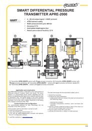
The <strong>PMS</strong>-<strong>920</strong> meter is equipped with one current input 0-20 / 4-20mA and one voltage<br />
input 0-5 / 1-5 / 0-10 / 2-10V. Current input has additionally overcurrent protection circuit,<br />
which protects standard resistor. The selection of active input is realised by software, and<br />
selected input can be changed at any time. Additionally the <strong>PMS</strong>-<strong>920</strong> allows user to select a<br />
conversion characteristic of several kinds: linear, square, square root, user defined (max.20<br />
points length) and volume characteristics of a cylindrical tank in the vertical and horizontal<br />
position. Result is showed on 4-digit LED display. Displayed values range can be selected by<br />
user, from -999 to 9999, plus decimal point.<br />
The device can be equipped with one or two relay (or OC type) outputs. Device <strong>PMS</strong>-<br />
<strong>920</strong> is equipped with RS-485 / Modbus RTU communication interface and sensor supply<br />
output. The meter can be ordered in two power supply versions.<br />
<strong>PMS</strong>-<strong>920</strong> can be used for controlling and regulation of processes need proportional and<br />
threshold control like: temperature processes (heating or cooling), valves controlling or other.<br />
3. TECHNICAL DATA<br />
Power supply voltage<br />
(depending on version)<br />
External fuse (required)<br />
Power consumption<br />
4<br />
Current input<br />
Current measurement accuracy<br />
85...230...260V AC/DC; 50 ÷ 60 Hz (separated)<br />
or 19...24...50V DC and 16...24...35V AC (separated)<br />
T - type, max. 2 A<br />
max. 4.5 VA @ 85 ÷ 260V AC/DC<br />
max. 4.5 VA @ 16V ÷ 35V AC<br />
max. 4.5 W @ 19V ÷ 50V DC<br />
0÷20 mA, 4÷20 mA overload protected,<br />
maximum input current about 40 mA<br />
Current input resistance < 65 Ω (typical 55 Ω)<br />
Voltage input<br />
± 0,1% @ 25°C; ± one digit (for 0÷20 mA range)<br />
0÷5 V, 1÷5 V, 0÷10 V, 2÷10 V
User manual for meter with U/I input <strong>PMS</strong>-<strong>920</strong><br />
Voltage measurement accuracy<br />
Voltage input resistance<br />
± 0,1% @ 25°C; ± one digit (for 0÷10 V range)<br />
> 50 kΩ<br />
Temperature stability 50 ppm / °C<br />
Display range<br />
-999 ÷ 9999, plus decimal point<br />
Accepted prolonged input overload: 20%<br />
Outputs<br />
relay:<br />
or OC-type:<br />
sensor power supply:<br />
0, 1 or 2 NO, 1A/250V AC (cos ϕ = 1)<br />
0, 1 or 2 30mA / 30VDC / 100mW<br />
24V +5%, -10% / max. 100 mA, stabilized<br />
Communication interface<br />
Baud rate<br />
Display<br />
(depending on version)<br />
Data memory<br />
RS 485, 8N1 and 8N2, Modbus RTU, not separated<br />
1200 bit/s ÷ 115200 bit/s<br />
LED, 4 digit, 13mm height, two-colour (red and green)<br />
or (for IP 65 version) 5 digit, 9mm height, red<br />
non-volatile memory, EEPROM type<br />
Protection level (depending on<br />
display size)<br />
5 x 9mm version: IP 65 (from front), optional version with panel cut-out<br />
sealing available<br />
IP 20 (housing and connection clips)<br />
4 x 13mm version: IP 40 (from front)<br />
IP 20 (housing and connection clips)<br />
Housing type<br />
Housing material<br />
Housing dimensions<br />
Mounting hole<br />
Assembly depth<br />
Panel thickness<br />
Operating temperature<br />
Storage temperature<br />
Humidity<br />
Altitude<br />
panel<br />
NORYL - GFN2S E1<br />
72 x 36 x 97 mm<br />
66.5 x 32.5 mm<br />
min. 102 mm<br />
max. 5 mm<br />
0°C to +50°C<br />
-10°C to +70°C<br />
5 to 90% no condensation<br />
up to 2000 meters above sea level<br />
Screws tightening max. torque 0,5 Nm<br />
Max. connection leads diameter 2,5 mm 2<br />
Safety requirements according to: PN-EN 61010-1<br />
installation category: II<br />
pollution degree: 2<br />
voltage in relation to ground: 300V AC<br />
insulation resistance: >20MΩ<br />
insulation strength between power supply and<br />
input/output terminal: 1min. @ 2300V<br />
insulation strength between relays terminal:<br />
1min. @ 1350V<br />
5
User manual for meter with U/I input <strong>PMS</strong>-<strong>920</strong><br />
EMC according to: PN-EN 61326-1<br />
!<br />
This is a class A unit. In a residential or a similar area it can cause radio<br />
frequency interference. In such cases the user can be requested to use<br />
appropriate preventive measures.<br />
4. DEVICE INSTALLATION<br />
The unit has been designed and manufactured in a way assuring a high level of user<br />
safety and resistance to interference occurring in a typical industrial environment. In order to<br />
take full advantage of these characteristics installation of the unit must be conducted correctly<br />
and according to the local regulations.<br />
!<br />
4.1. UNPACKING<br />
- Read the basic safety requirements on page 3 prior to starting the installation.<br />
- Ensure that the power supply network voltage corresponds to the nominal<br />
voltage stated on the unit’s identification label.<br />
- The load must correspond to the requirements listed in the technical data.<br />
- All installation works must be conducted with a disconnected power supply.<br />
- Protecting the power supply connections against unauthorized persons must be<br />
taken into consideration.<br />
After removing the unit from the protective packaging, check for transportation damage. Any<br />
transportation damage must be immediately reported to the carrier. Also, write down the unit<br />
serial number located on the housing and report the damage to the manufacturer.<br />
Attached with the unit please find:<br />
- user’s manual,<br />
- warranty,<br />
- assembly brackets - 2 pieces.<br />
4.2. ASSEMBLY<br />
!<br />
- The unit is designed for mounting inside housings (control panel, switchboard)<br />
insuring appropriate protection against surges and interference. Metal housings<br />
must be connected to ground in a way that complies with the governing<br />
regulations.<br />
- Disconnect the power supply prior to starting assembly.<br />
- Check the connections are wired correctly prior to switching the unit on.<br />
!<br />
In order to install the unit, a 66.5 x 32.5 mm mounting hole (Figure 4.1) must be<br />
prepared. The thickness of the material of which the panel is made must not exceed<br />
5mm. When preparing the mounting hole take the grooves for catches located on<br />
6
User manual for meter with U/I input <strong>PMS</strong>-<strong>920</strong><br />
both sides of the housing into consideration (Figure 4.1). Place the unit in the<br />
mounting hole inserting it from the front side of the panel, and then fix it using the<br />
brackets (Figure 4.2). The minimum distances between the centre points of multiple<br />
units - due to the thermal and mechanical conditions of operation - are 91 mm x<br />
57mm (Figure 4.3).<br />
a)<br />
66,5 mm<br />
8 mm<br />
8 mm<br />
8 mm<br />
8 mm<br />
32,5 mm<br />
1 mm<br />
1 mm<br />
max. 5 mm<br />
b)<br />
68 mm<br />
32,5 mm<br />
max. 5 mm<br />
Figure 4.1. Mounting hole dimensions: a) recommended b) allowable<br />
7
User manual for meter with U/I input <strong>PMS</strong>-<strong>920</strong><br />
92 mm<br />
5 mm<br />
8,5 mm<br />
12 mm 10 mm<br />
16 mm<br />
Figure 4.2. Installing of brackets, and dimensions of connectors.<br />
91 mm<br />
57 mm<br />
Figure 4.3. Minimum distances when assembly of a number of units<br />
4.3. CONNECTION METHOD<br />
Caution<br />
8<br />
!<br />
- Installation should be conducted by qualified personnel . During installation all<br />
available safety requirements should be considered. The fitter is responsible for<br />
executing the installation according to this manual, local safety and EMC<br />
regulations.<br />
- The unit is not equipped with an internal fuse or power supply circuit breaker.<br />
Because of this an external time-delay cut-out fuse with a small nominal current<br />
value must be used (recommended bipolar, max. 2A) and a power supply circuitbreaker<br />
located near the unit. In the case of using a monopolar fuse it must be<br />
mounted on the phase cable (L).<br />
- The power supply network cable diameter must be selected in such a way that in<br />
the case of a short circuit of the cable from the side of the unit the cable shall be<br />
protected against destruction with an electrical installation fuse.
User manual for meter with U/I input <strong>PMS</strong>-<strong>920</strong><br />
!<br />
- Wiring must meet appropriate standards and local regulations and laws.<br />
- In order to secure against accidental short circuit the connection cables must be<br />
terminated with appropriate insulated cable tips.<br />
- Tighten the clamping screws. The recommended tightening torque is 0.5 Nm.<br />
Loose screws can cause fire or defective operation. Over tightening can lead to<br />
damaging the connections inside the units and breaking the thread.<br />
- In the case of the unit being fitted with separable clamps they should be inserted<br />
into appropriate connectors in the unit, even if they are not used for any<br />
connections.<br />
- Unused terminals (marked as n.c.) must not be used for connecting any<br />
connecting cables (e.g. as bridges), because this can cause damage to the<br />
equipment or electric shock.<br />
- If the unit is equipped with housing, covers and sealing to, protecting against<br />
water intrusion, pay special attention to their correct tightening or clamping. In the<br />
case of any doubt consider using additional preventive measures (covers, roofing,<br />
seals, etc.). Carelessly executed assembly can increase the risk of electric shock.<br />
- After the installation is completed do not touch the unit’s connections when it is<br />
switched on, because it carries the risk of electrical shock.<br />
Due to possible significant interference in industrial installations appropriate measures<br />
assuring correct operation of the unit must be applied. To avoid the unit of improper<br />
indications keep recommendations listed below.<br />
– Avoid running signal cables and transmission cables together with power supply cables<br />
and cables controlling inductive loads (e.g. contactors). Such cables should cross at<br />
a right angle.<br />
– Contactor coils and inductive loads should be equipped with interference protection<br />
systems, e.g. RC-type.<br />
– Use of screened signal cables is recommended. Signal cable screens should be<br />
connected to the earthing only at one of the ends of the screened cable.<br />
– In the case of magnetically induced interference the use of twisted pair of signal cables is<br />
recommended. Twisted pair (best if shielded) must be used with RS-485 serial<br />
transmission connections.<br />
– In the case of measurement or control signals are longer than 30m or go outside of the<br />
building then additional safety circuits are required.<br />
– In the case of interference from the power supply side the use of appropriate interference<br />
filters is recommended. Bear in mind that the connection between the filter and the unit<br />
should be as short as possible and the metal housing of the filter must be connected to<br />
the earth with the largest possible surface. The cables connected to the filter output must<br />
not be run with cables with interference (e.g. circuits controlling relays or contactors).<br />
Connections of power supply voltage and measurement signals are executed using the<br />
screw connections on the back of the unit’s housing.<br />
9
User manual for meter with U/I input <strong>PMS</strong>-<strong>920</strong><br />
max. 2 mm<br />
6-7 mm<br />
Figure 4.4. Method of cable insulation replacing and cable terminals<br />
Power<br />
supply<br />
(depending on version)<br />
1 2<br />
R2<br />
(optional)<br />
13 14<br />
3 4<br />
R1<br />
(optional)<br />
+24V +5%, -10%<br />
+ Uo -<br />
16<br />
17<br />
18 19 20<br />
6 7 8 9<br />
n.c. +<br />
10<br />
n.c.<br />
0/4-20mA<br />
GND<br />
0/1 - 5V, 0/2 - 10V<br />
Figure 4.5. Terminals description (relay outputs)<br />
+<br />
Power<br />
supply<br />
(depending on version)<br />
1 2<br />
OC1, OC2:<br />
Umax = 30V DC<br />
Imax = 30mA<br />
Pmax = 100mW<br />
(optional)<br />
OC2<br />
- +<br />
13 14<br />
3 4<br />
- +<br />
OC1<br />
(optional)<br />
+24V +5%, -10%<br />
+ Uo -<br />
RS - 485<br />
Imax = 100mA<br />
GND DATA+<br />
DATA-<br />
RS - 485<br />
Imax = 100mA<br />
GND DATA+<br />
DATA-<br />
16<br />
17<br />
18 19 20<br />
6 7 8 9<br />
n.c. +<br />
+<br />
10<br />
n.c.<br />
0/4-20mA<br />
GND<br />
0/1 - 5V, 0/2 - 10V<br />
!<br />
Figure 4.6. Terminals description (OC-type outputs)<br />
All connections must be made while power supply is disconnected !<br />
10
+<br />
User manual for meter with U/I input <strong>PMS</strong>-<strong>920</strong><br />
internally connected<br />
+ -<br />
24V DC<br />
16 17<br />
6 7 8 9 10<br />
6 7 8 9 10<br />
- +<br />
+<br />
-<br />
-<br />
+<br />
Figure 4.7. Connection of 2-wire current converters<br />
+ -<br />
16 17<br />
internally connected<br />
6 7 8 9 10<br />
6 7 8 9 10<br />
24V DC<br />
- +<br />
+<br />
-<br />
+<br />
-<br />
Figure 4.8. Connection of 3-wire current converters<br />
- +<br />
16 17<br />
internally connected<br />
6 7 8 9 10<br />
6 7 8 9 10<br />
24V DC<br />
- +<br />
+<br />
-<br />
+<br />
+<br />
-<br />
Figure 4.9. Connection of voltage converters<br />
11
User manual for meter with U/I input <strong>PMS</strong>-<strong>920</strong><br />
R2<br />
L<br />
N<br />
1 2<br />
R1<br />
3 4<br />
13 14<br />
FUSE<br />
FUSE<br />
L<br />
N<br />
Depending on version:<br />
85...230...260V AC/DC or<br />
19...24...50V DC; 16...24...35V AC<br />
Figure 4.10. Connection of power supply and relays<br />
!<br />
Contacts of relay outputs are not equipped with spark suppressors. While use<br />
the relay outputs for switching of inductive loads (coils, contactors, power<br />
relays, electromagnets, motors etc.) it is required to use additional<br />
suppression circuit (typically capacitor 47nF/ min. 250VAC in series with<br />
100R/5W resistor), connected in parallel to relay terminals or (better) directly<br />
on the load. In consequence of using the suppression circuit, the level of<br />
generated electromagnetic disturbances is lower, and the life of relay contacts<br />
rises.<br />
12
User manual for meter with U/I input <strong>PMS</strong>-<strong>920</strong><br />
a) L b)<br />
L<br />
3 4 3 4<br />
!<br />
!<br />
N<br />
N<br />
Figure 4.11. Examples of suppression circuit connection:<br />
a) to relay terminals; b) to the inductive load<br />
OC1<br />
3 4<br />
- +<br />
Logic controller<br />
+<br />
-<br />
voltage input<br />
24 V<br />
Uo<br />
16 17<br />
+ -<br />
OC1<br />
3 4<br />
- +<br />
LED 10 mA<br />
R<br />
2k2<br />
Uo<br />
16 17<br />
+ -<br />
Figure 4.12. Example of OC-type outputs connection<br />
13
User manual for meter with U/I input <strong>PMS</strong>-<strong>920</strong><br />
4.4. MAINTENANCE<br />
The unit does not have any internal replaceable or adjustable components available to<br />
the user. Pay attention to the ambient temperature in the room where the unit is operating.<br />
Excessively high temperatures cause faster ageing of the internal components and shorten the<br />
fault-free time of the unit's operation.<br />
In cases where the unit gets dirty do not clean with solvents. For cleaning use warm water with<br />
small amount of detergent or in the case of more significant contamination ethyl or isopropyl<br />
alcohol.<br />
!<br />
Using any other agents can cause permanent damage to the housing.<br />
Product marked with this symbol should not be placed in municipal waste. Please<br />
check local regulations for disposal of electronic products.<br />
5. FRONT PANEL DESCRIPTION<br />
alarm LED indicator (AL)<br />
AL<br />
display<br />
R1<br />
Thresholds exceeding<br />
LED indicators (R)<br />
R2<br />
ESC<br />
MENU<br />
ENTER<br />
programming pushbuttons<br />
Symbols and functions of push-buttons:<br />
ESC<br />
MENU<br />
ENTER<br />
Symbol used in the manual: [ESC/MENU]<br />
Functions:<br />
• Enter to main menu ( press and hold by at least 2 sec.)<br />
• Exit the current level and Enter to previous menu (or measure mode)<br />
• Cancel the changes made in parameter being edited<br />
Symbol used in the manual: [ENTER]<br />
Functions:<br />
• Start to edit the parameter<br />
• Enter to the sub-menu,<br />
• Confirmation of changes made in parameter being edited<br />
Symbol used in the manual: [^] [v]<br />
Functions:<br />
• Change of the present menu,<br />
• Modification of the parameter value,<br />
• Change of the display mode.<br />
14
User manual for meter with U/I input <strong>PMS</strong>-<strong>920</strong><br />
6. PRINCIPLE OF OPERATION<br />
After turning the power supply on, device ID and software version are showed on the<br />
display, next the controller goes to the measurement mode.<br />
6.1. MEASUREMENT MODE<br />
In the measure mode, the measurement results, converted over selected characteristic,<br />
are displayed on the LED display. The measurement range equal to the nominal range is<br />
called: nominal measurement range, and the measurement range equal to the extended<br />
nominal range is called: permissible measurement range (Figure 6.1, 6.2).<br />
”Lo r” parameter<br />
nominal measurement range<br />
”Hi r” parameter<br />
4 mA 20 mA<br />
permissible measurement range<br />
Figure 6.1. Definitions of measurement ranges in mode 4 ÷ 20mA<br />
If the result of measurement exceeds the permissible measurement range, warning ”-Hi-” or<br />
”-Lo-” is displayed rather than input signal, depends on exceeded value (see description of<br />
“Lo r” i “Hi r” parameters, paragraph ”inPt” menu).<br />
nominal measurement range<br />
”Hi r” parameter<br />
0 mA 20 mA<br />
permissible measurement range<br />
Figure 6.2. Definitions of measurement ranges in mode 0 ÷ 20mA<br />
i<br />
If the measurement value do not exceeds permissible measurement range but<br />
displayed value exceeds range -999 ÷ 9999, the warning ”-Ov-” is displayed rather<br />
than the calculated result.<br />
In the measurement mode user can check main thresholds values. After pressing [^] or<br />
[v] button, name of the threshold (e.g. ”rEL1”) and his value will be displayed on the display<br />
in alternating mode. If [^] or [v] will be pressed in 5 sec again, the next threshold will be<br />
displayed, else the device comes back to the measurement mode. If a free access is enabled<br />
(see description of ”SECu” menu), user can change the value of particular threshold pressing<br />
button [ENTER] (see: PARAMETERS EDITION).<br />
Input type, range of displaying values, characteristic of conversion,<br />
decimal point<br />
15
User manual for meter with U/I input <strong>PMS</strong>-<strong>920</strong><br />
position and measure filtering ratio, are user configurable parameters. All accessible<br />
parameters can be changed by entering the menu (see: DEVICE PROGRAMMING). Use the<br />
local keyboard or the remote controller to do it. (Note: all parameters can be remote changed<br />
via RS-485 interface).<br />
i<br />
Configuration of the device (via menu or RS-485 interface) do not stops measures.<br />
6.2. DETECTION OF THE PEAK VALUES<br />
The <strong>PMS</strong>-<strong>920</strong> controller is equipped with peaks detection function. It can detect a peaks<br />
of the input signal and display their values. Presets connected with this function are placed in<br />
”HOLd” menu (see description of ”HOLd” menu). The detection of the peak can be done if<br />
the measured signal raises and drops of value at least equal to parameter ”PEA”. Detected<br />
peaks are displayed during the time defined by parameter ”timE”. If a new peak will be<br />
detected while one is displayed, this new peak will be displayed and display time counter will<br />
be cleared (Figure 6.3). If no peaks are detected while time ”timE” elapses, device starts to<br />
show the current value of input signal again. If „HdiS”=”HOLD” then setting parameter<br />
"timE"=0.0 causes holding peak value until [ESC] button is pressed. If „HdiS”=”rEAL” then<br />
value "timE"=0.0 means no holding. Displaying peak value is signalized by flashing most right<br />
decimal point.<br />
The relays/LEDs can be controlled depend on the current value of input signal or the<br />
peak value (see ”HOLd” menu).<br />
measure<br />
”timE”<br />
”timE”<br />
”PEA”<br />
”PEA”<br />
real measurement result<br />
display value<br />
time<br />
Figure 6.3. Process of peaks detection<br />
6.3. CONTROL OF THE RELAY OUTPUTS<br />
The control of the object (measured signal) is realized via relay outputs. Front panel<br />
LEDs named „R” indicates the state of particular relay output.<br />
i<br />
If device is not equipped with one or more relay outputs, menus refer to this relays<br />
are available, but apply to LED indicators only. In such case LEDs indicates<br />
exceeding of particular thresholds.<br />
16
User manual for meter with U/I input <strong>PMS</strong>-<strong>920</strong><br />
Modes of the control can be changed depend on the values of parameters “SEtP”, “SEt2”,<br />
“HYSt”, “modE”, “t on”, “toFF”, “unit” and “AL”. Depend on “modE” parameter, relays<br />
can be not used or controlled over one or two thresholds values.<br />
If one threshold is used (Figure 6.4) the relay can be turned on (“modE” = ”on”) or off<br />
(“modE” = ”oFF”) when the input signal value is contained in zone A. If two thresholds are<br />
used (Figure 6.5) the relay will be turned on when value of input signal is contained in zone A<br />
(“modE” = ”in”) or zone B (“modE” = ”out”) and turned off if the signal is contained in the<br />
second one.<br />
state of<br />
relay/LED<br />
”SEtP” parameter<br />
zone B<br />
zone A<br />
measure<br />
”HYSt” parameter<br />
Figure 6.4. One threshold control of the relay/LED outputs<br />
state of<br />
relay/LED<br />
”SEtP” or ”SEt2” parameter<br />
zone B<br />
zone A<br />
zone B<br />
”HYSt” parameter<br />
measure<br />
i<br />
Figure 6.5. Two threshold control of the relay/LED outputs<br />
The relay outputs and LEDs (named R) can be controlled depend on both - the<br />
current value and the peak value (when peak detection is active) of the input signal.<br />
17
User manual for meter with U/I input <strong>PMS</strong>-<strong>920</strong><br />
6.3.1. One threshold mode<br />
Figure 6.6 presents the principle of relay outputs operation for one threshold mode, and<br />
an example values of other parameters.<br />
a)<br />
displayed value<br />
zone A<br />
A<br />
measured<br />
t A<br />
t B t C<br />
signal t D<br />
B<br />
B ON<br />
“SEtP” parameter<br />
(expected signal value)<br />
B OFF<br />
D ON<br />
time<br />
b)<br />
c)<br />
d)<br />
e)<br />
zone B<br />
relay state<br />
(modE = on<br />
t on = 0<br />
toFF = 0)<br />
relay state<br />
(modE = oFF<br />
t on = 0<br />
toFF = 0)<br />
relay state<br />
(modE = on<br />
t on > 0<br />
toFF > 0)<br />
relay state<br />
(modE = oFF<br />
t on > 0<br />
toFF > 0)<br />
closed<br />
open<br />
open<br />
closed<br />
“HYSt” parameter<br />
(allowed signal<br />
deviation)<br />
Description:<br />
A, B, C, D - points where measured signal exceeds border values (expected value ± allowed deviation)<br />
B ON ,B OFF ,D ON ,D OFF - relays state changes moments: (for “t on” > 0, “toFF” > 0)<br />
t A , t B , t C , t D - time periods while input signal is in zone A or zone B<br />
C<br />
“t on”<br />
parameter<br />
open<br />
“toFF”<br />
parameter<br />
open<br />
closed<br />
closed<br />
“toFF”<br />
parameter<br />
D<br />
“t on”<br />
parameter<br />
D OFF<br />
time<br />
time<br />
time<br />
time<br />
Figure 6.6. Principle of LED/relay output operation for one threshold mode<br />
Parameter “SEtP” sets a threshold of the relay, and parameter “HYSt” sets a<br />
hysteresis of the relay (Figure 6.6 a). The relay can change his state only when input value<br />
exceeds (over or under) border value and t A ,t B ,t C ,t D times (Figure 6.6) are bigger than the<br />
time defined by parameters “t on”, “toFF” and “unit”. Border values means values equal<br />
threshold+hysteresis and threshold-hysteresis respectively.<br />
If “t on” and “toFF” parameters are set to “0”, then the relay state will be changed<br />
as soon as input value exceeds any of the border values (see points A and C, Figure 6.6 a,<br />
b, c).<br />
If values of “t on” or/and “toFF” are positive, then relay state will be turned on if the<br />
input value exceeds the border values and stay bigger (or lower) during at least<br />
“t on” (see points B ON, D ON, Figure 6.6 a, d, e). Similarly, the relay will be turned off if time<br />
“toFF” elapse since the input signal value exceeds any of the border values (see points<br />
B OFF, D OFF, Figure 6.6 a, d, e).<br />
18
User manual for meter with U/I input <strong>PMS</strong>-<strong>920</strong><br />
If t A ,t B ,t C or t D (when input signal stay in zone A or zone B) are lower than parameters “t on”<br />
or “toFF”, the relay will not change his state (see points A and C, Figure 6.6 a, d, e).<br />
The state of relay output while the input value exceeds the border values (points A, B, C,<br />
D) is described by parameter “modE”. The relay can be turned on (“modE” = ”on”), or<br />
turned off (“modE” = ”oFF”) when input signal value is contained in zone A (Figure 6.6 a).<br />
The parameter “AL” allow user to set the relay output behaviour in critical situations (e.<br />
g. Input values exceeds permissible measurement range). User can select that the relays<br />
will be turned on, turned off,or not changed in critical situations.<br />
All parameters connected with relay outputs are described in paragraph ”rEL1” menu.<br />
6.3.2. Two thresholds mode<br />
displayed value<br />
t A<br />
t B<br />
t C<br />
measure<br />
t D<br />
d signal<br />
C<br />
t E<br />
“HYSt” parameter<br />
B ON<br />
a)<br />
zone B C OFF<br />
C ON<br />
E<br />
zone A<br />
A<br />
B<br />
D<br />
E OFF<br />
“SEtP” or “SEt2”<br />
parameter<br />
“HYSt” parameter<br />
zone B<br />
b)<br />
c)<br />
relay state<br />
(modE = in<br />
t on = 0<br />
toFF = 0)<br />
relay state<br />
(modE = out<br />
t on = 0<br />
toFF = 0)<br />
closed<br />
open<br />
B OFF<br />
E ON<br />
time<br />
open<br />
closed<br />
time<br />
time<br />
d)<br />
e)<br />
relay state<br />
(modE = in<br />
t on > 0<br />
toFF > 0)<br />
relay state<br />
(modE = out<br />
t on > 0<br />
toFF > 0)<br />
“t on” parameter<br />
“toFF” parameter<br />
closed<br />
open<br />
“toFF” parameter “t on” parameter<br />
closed<br />
open<br />
“t on” parameter “toFF” parameter<br />
time<br />
time<br />
Objaśnienie:<br />
A, B, C, D, E - points where measured signal exceeds border values (expected value ± allowed deviation)<br />
B ON ,B OFF ,C ON ,C OFF ,E ON ,E OFF - relays state changes moments: (for “t on” > 0, “toFF” > 0)<br />
t A , t B , t C , t D , t E<br />
- time periods while input signal is in zone A or zone B<br />
Figure 6.7. Principle of LED/relay output operation for two thresholds mode<br />
19
User manual for meter with U/I input <strong>PMS</strong>-<strong>920</strong><br />
Figure 6.7 presents the principle of relay outputs operation for two thresholds mode, and an<br />
example values of other parameters. In this mode parameter “SEt2” is accessible in common<br />
with “SEtP”, this parameter describes a second threshold of the relay output. The parameters<br />
“HYSt”, “modE”, “t on”, “toFF”, “unit” and “AL” are connected with both “SEtP” and<br />
“SEt2” thresholds. While the controlling process, the relay output changes his state depends<br />
of both “SEtP” and “SEt2” thresholds in similar way as it was described in one threshold<br />
mode.<br />
If two threshold mode is used, “modE” parameter defines state of the relay output when<br />
the input value occurs in a particular zone defined by border values of both thresholds. The<br />
relay can be turned on if the input value is contained in zone A (“modE” = ”in”) or zone B<br />
(“modE” = ”out”) and turned off if it is contained in the second one (Figure 6.7).<br />
i<br />
The sequence of thresholds “SEtP” and “SEt2” can be set in any order, due to the<br />
control of relay outputs is done depend on difference between thresholds values<br />
(zone A ) and outside of threshold values (zone B).<br />
7. DEVICE PROGRAMMING<br />
The device menu allow user to set all parameters connected to operation of<br />
measurement input, control modes, critical situations behaviour, communication via RS-485<br />
and access settings. The meaning of the particular parameters is described in paragraph<br />
MENU DESCRIPTION.<br />
Some of the parameters can be accessed without menu entering (quick view mode).<br />
After pressing [^] or [v] button, name of the threshold (e.g.”rEL1”) and his value will be<br />
displayed on the display in alternating mode. If [^] or [v] will be pressed in 5 sec again, the<br />
next threshold will be displayed, else the device comes back to the measurement mode. If a<br />
free access is enabled (see description of ”SECu” menu), user can change the value of<br />
particular threshold pressing button [ENTER] (see: PARAMETERS EDITION).<br />
i<br />
If particular parameter has been changed and confirmed in quick view mode, its<br />
new value is displayed in alternating mode with parameter name by few seconds.<br />
Confirmed changes may be checked or user can switch viewed parameter pressing<br />
[^] or [v] button.<br />
7.1. PROGRAMMING MENU<br />
To enter main menu (being in the measurement mode) operator must to press and hold<br />
at least 2 sec. [ESC/MENU] button.<br />
If the user password is defined (see parameter “Scod“, menu ”SECU”), operator have<br />
to enter correct one before proceeding to menu options . Entering of the passwords is similar<br />
to the edition of numeric parameters (see: PARAMETERS EDITION ), however presently editing<br />
digit is showed only on the display, other digits are replaced by “-” sign.<br />
After entering of last digit of the password first menu position will be displayed (if the password<br />
is correct) or warning ”Err” in other case.<br />
20<br />
!<br />
Pay attention when device parameters are being changed. If it is possible, turn off<br />
controlled installation (machine).
User manual for meter with U/I input <strong>PMS</strong>-<strong>920</strong><br />
Functions of the buttons while sub-menu and parameters choice:<br />
Selection of sub-menu or parameter for editing. Name of selected item (submenu<br />
or parameter) is displayed.<br />
ENTER<br />
ESC<br />
MENU<br />
Operation of [ENTER] button depend on present menu position:<br />
• if the name of some sub-menu is displayed - enter this sub-menu; name<br />
of the first parameter (or next level sub-menu) is displayed,<br />
• if the name of some parameter is displayed - enter the edition of this<br />
parameter; present value of the parameter is displayed,<br />
[ESC/MENU] button allow user to exit present menu level and goes to upper<br />
level menu (or measurement mode).<br />
i<br />
After about 1 min. since last use of the buttons, device exits the menu mode and<br />
returns to the measurement mode (only if no parameters are in editing mode).<br />
7.2. PARAMETERS EDITION<br />
To start edition of any parameter user should select name of desired one using [^] [v]<br />
buttons and then press [ENTER].<br />
7.2.1. Numeric parameters (digit change mode)<br />
Numerical parameters are displayed as decimal numbers. The mode of its new value<br />
entering depends on chosen edit method ( see parameter „Edit”).<br />
In mode “by digit” („Edit”=”dig”) pressing one of the keys [^] or [v] causes change of<br />
current position (flashing digit) or the sign (+/-). Short pressing of the [ENTER] button causes<br />
change of the position (digit).<br />
Press [ENTER] at least 2 seconds to accept the changes, after that question ”SEt?” is<br />
displayed, and user must to confirm (or cancel) the changes. To conform changes (and story it<br />
in EEPROM) press [ENTER] button shortly after ”SEt?” is displayed. To cancel the changes<br />
press [ESC] button shortly after ”SEt?” is displayed. After that device returns to the menu.<br />
7.2.2. Numeric parameters (slide change mode)<br />
In “slide change” mode („Edit”=”Slid”), buttons [^] and [v] has different functions.<br />
To increase edited value press (or press and hold) [^] button only, the increasing<br />
became quickest as long as button [^] is pressed. To slow down the increasing, button [v] can<br />
be used. If [v] is pressed shortly (and button [^] is still pressed), increasing slow down for<br />
a moment only, if [v] is pressed and held while button [^] is still pressed the increasing slow<br />
down and will be kept on lower speed.<br />
To decrease edited value press (or press and hold ) [v] button only. The decreasing<br />
became quickest as long as button [v] is pressed. To slow down the decreasing, button [^]<br />
can be used. If [^] is pressed shortly (and button [v] is still pressed), decreasing slow down for<br />
a moment only, if [^] is pressed and held while button [v] is still pressed the decreasing slow<br />
down and will be kept on lower speed.<br />
21
User manual for meter with U/I input <strong>PMS</strong>-<strong>920</strong><br />
Press [ENTER] at least 2 seconds to accept the changes, after that question ”Set?” is<br />
displayed, and user must to confirm (or cancel) the changes. To conform changes (and story it<br />
in EEPROM) press [ENTER] button shortly after ”SEt?” is displayed. To cancel the changes<br />
press [ESC] button shortly after ”SEt?” is displayed. After that device returns to the menu.<br />
7.2.3. Switch parameters (“LIST” type)<br />
Switch parameters can be described as a sets of values (a lists) out of which only one of<br />
the options available on the list can be selected for the given parameter. Options of switching<br />
parameter are selected using [^], [v] keys.<br />
Short pressing of [ENTER] causes in displaying of the acknowledge question (”SEt?”). If<br />
key [ENTER] is pressed again, the changes are accepted, stored in EEPROM end the edition<br />
process finished. Pressing the key [ESC] after ”SEt?” causes in cancelling of made changes<br />
and returning to menu.<br />
Functions of buttons when editing numeric and switching parameters:<br />
While editing numeric parameter:<br />
• change of current (flashing) digit<br />
• slide change of value (acceleration, deceleration, direction change)<br />
While editing switch parameter - selection of switch parameter.<br />
ENTER<br />
ESC<br />
MENU<br />
If numerical parameter is being edited, a short press of [ENTER] button<br />
change edited position. A long press of [ENTER] button (at lest 2 sec.)<br />
causes of display a ”SEt?” ask, which allow user to make sure if change of<br />
the parameter value is correct. If switch parameter is being edited, a short<br />
press of [ENTER] button causes of display a ”SEt?” ask. When [ENTER]<br />
button is pressed again (while ”SEt?” is displayed) the new value of the<br />
parameter is stored in EEPROM memory.<br />
Pressing this button operator can cancel the changes done up to now (if they<br />
were not approved by [ENTER] button after the ”SEt?” ask) and come back<br />
to menu<br />
7.3. MENU DESCRIPTION<br />
“- - - -” - password checking. If some password different from „0000” is set, then every<br />
enter to main menu follows the entering of password. If entered password is<br />
correct then first menu position will be displayed else warning ”Err”, and unit<br />
returns to measurement mode.<br />
i<br />
Due to problem with direct displaying of “m” and “K” letters, they are exchanged<br />
with special signs “ “ for “m” and “ “ for K respectively. However, in user manual<br />
letters „m” and “K” are used to make it more readable (example: “modE”, “tc K”).<br />
22
User manual for meter with U/I input <strong>PMS</strong>-<strong>920</strong><br />
7.3.1. “rEL1” menu<br />
This menu allows to configure the operation mode of relays and LEDs marked „R” (e.g. „R1”).<br />
If there are few relay outputs available, then every output has its own configuration menu<br />
(e.g. menu „rEL2” for relay (LED) „R2”). Principle of the relays operation is described in<br />
paragraph CONTROL OF THE RELAY OUTPUTS.<br />
i<br />
“SEtP”<br />
“SEt2”<br />
“HYSt”<br />
i<br />
• The relay outputs and LEDs (named R) can be controlled depend on both - the<br />
current value and the peak value (when peak detection is active) of the input<br />
signal.<br />
• If device is not equipped with one or more relay outputs, menus refer to this<br />
relays are available, but apply to LED indicators only. In such case LEDs<br />
indicates exceeding of particular thresholds.<br />
- first threshold of the relay (range -999 ÷ 9999). Negative values can be input by<br />
selecting a “-” sign on first digit (to change value use [^] and [v] buttons).<br />
Threshold is the medium value of relay hysteresis.<br />
- second threshold of the relay (range -999 ÷ 9999). Negative values can be input<br />
by selecting a “-” sign on first digit ( to change value use [^] and [v] buttons). This<br />
threshold is accessible when ”modE” parameter is set to „in” or „out” value.<br />
Threshold is the medium value of relay hysteresis.<br />
- hysteresis of relay (range 0 ÷ 999). Full hysteresis of the relay is equal to 2x<br />
“HYSt” parameter. The relay state can change when an input signal is out of<br />
threshold-hysteresis to threshold+hysteresis zone.<br />
Presented parameters should be set to ensure that ”SEtP” + ”HYSt”,<br />
”SEt2” + ”HYSt”, ”SEtP” - ”HYSt” or ”SEt2” - ”HYSt” do not exceeds the<br />
measure range. Additionally, in two threshold mode (“modE”= „in” or „out”), the<br />
hysteresis for both thresholds must not cover each other (in other case relay can't<br />
change his state).<br />
“modE” - relay operation mode:<br />
“noAC”<br />
“on”<br />
“oFF”<br />
“in”<br />
- the relay is not active (permanent turned off)<br />
- one threshold mode, the relay is turned ON when input signal exceeds<br />
SEtP + HYSt value, and is turned off back when the input signal became<br />
lower than SEtP – HYSt,<br />
- one threshold mode, the relay is turned OFF when input signal exceeds<br />
SEtP + HYSt value, and is turned on back when the input signal became<br />
lower than SEtP – HYSt,<br />
- two threshold mode, the relay is turned ON when the input signal is<br />
bigger than “lower threshold + HYSt” and lower than “bigger<br />
threshold – HYSt”, and turned off when the input signal is contained in<br />
the second zone. The bigger threshold means bigger one of “SEtP”<br />
and “SEt2” thresholds, the lower threshold” means lower one of<br />
“SEtP” and “SEt2” thresholds.<br />
23
User manual for meter with U/I input <strong>PMS</strong>-<strong>920</strong><br />
“out”<br />
- two threshold mode, relay is turned ON when the input value is bigger<br />
than “bigger threshold + HYSt” and lower than “lower threshold –<br />
HYSt”, and turned on when the input signal is contained in the second<br />
zone. The bigger threshold means bigger one of “SEtP” and “SEt2”<br />
thresholds, the lower threshold” means lower one of “SEtP” and<br />
“SEt2” thresholds.<br />
“modb” - the relay is controlled via RS-485 interface, independently on the input<br />
signal.<br />
i<br />
• LEDs light when relays are closed, independently of relays' mode.<br />
• When power supply fail, unit do not store relays state selected by RS-485<br />
interface.<br />
“t on” - turn on delay time, the relay is turned on with delay equal “t on” if the input value<br />
exceeds appropriate border value (defined with threshold and hysteresis), at<br />
least “t on” time. “t on” range 0 ÷ 99.9, defined with 0.1 sec. resolution. Unit of<br />
this parameter is set by “unit” parameter.<br />
“toFF”<br />
i<br />
“unit”<br />
- turn off delay time, the relay is turned off with delay equal “toFF” if the input value<br />
exceeds appropriate border value (defined with threshold and hysteresis), at<br />
least “toFF” time. “toFF” range 0 ÷ 99.9, defined with 0.1 sec. resolution. Unit of<br />
this parameter is set by “unit” parameter.<br />
If time when the input signal exceeds some border value is shorter than “t on” or<br />
“toFF” time, the relay do not change his state (see paragraph: CONTROL OF<br />
THE RELAY OUTPUTS).<br />
- unit of time for “t on” i “toFF” parameters. Can be set on one of two values:<br />
“min”<br />
“SEC”<br />
- minutes,<br />
- seconds.<br />
“AL”<br />
- this parameter defines the relay reaction when some critical situations occurs:<br />
“noCH”<br />
“on”<br />
“oFF”<br />
- relay do not change his state,<br />
- relay will be turned on,<br />
- relay will be turned off.<br />
If parameter “modE” is set to “on” , “oFF”, “in” or “Out” the “critical situation”<br />
means that allowable measurement range is exceeded.<br />
If parameter “modE” is set to “modb”, the “critical situation” means<br />
communication delay (when no data is received) longer than “mbtO” parameter<br />
(see description: “rS” menu).<br />
24
User manual for meter with U/I input <strong>PMS</strong>-<strong>920</strong><br />
i<br />
• If option “noCH” is selected for “AL” parameter, behaviour of the relay may<br />
depend on “FiLt” parameter in some cases. If “FiLt” is set to big value and the<br />
input signal drops, result value of the measure will change slow, causes of<br />
turning on or off relay due to thresholds values. The critical situation is slowly<br />
detected, so it is impossible to predict the relay state in that situations.<br />
• If parameter „AL” = „on”, the relay will be turned on in the critical situations,<br />
even if his parameter “modE” = ”noAC”.<br />
7.3.2. “inPt” menu<br />
This menu presets the measurement input:<br />
“tYPE" - type of the input / sensor. This parameter can be set to values:<br />
”0-20”, “4-20” - current inputs.<br />
”0-10”, “2-10”, ”0-5”, “1-5” - voltage inputs.<br />
Displayed values are defined by parameters “Lo C”,”Hi C” (or by user defined<br />
characteristic points) and parameter ”Pnt”.<br />
”CHAr” - this option presets type of the conversion characteristic, and can be set to:<br />
”Lin” - linear<br />
“Sqr” - square<br />
When one of those characteristics is chosen display<br />
“Sqrt” - square root<br />
range is defined by “Lo C” and “Hi C”.<br />
i<br />
“USEr”<br />
“tn v”<br />
“n h”<br />
- user defined characteristic. Maximal length 20 points. Every point is<br />
defined by user. Adding, Editing and Deleting of points is done by options<br />
„AddP”, „EdtP”, „dELP” („InPt” menu) respectively.<br />
- volume characteristics of a cylindrical tank in the vertical position,<br />
determined by parameters: „t h1”, ”t h2”, „t h3”, „t d”, „t Sn”, „t Sh” in „InPt”<br />
menu (see below for details of the parameters),<br />
- volume characteristics of a cylindrical tank in the horizontal position,<br />
determined by parameters: „t h1”, ”t h2”, „t h3”, „t d”, „t Sn”, „t Sh” in „InPt”<br />
menu (see below for details of the parameters).<br />
If user defined characteristic is selected, and if number of defined points is lower<br />
than 2 then warning ”Errc” is displayed in measurement mode.<br />
The process of displayed result calculation is described in details in DISPLAY VALUES<br />
CALCULATION paragraph.<br />
”FiLt” - this parameter sets filtration rate. It can be set to values from 0 (no filtration ) to 5<br />
(strongest filtration – time window about 2 sec).<br />
”Pnt”<br />
- decimal point position. It can be set to one of:<br />
“ 0”, “ 0.0”, “ 0.00”, “0.000”<br />
Decimal point position is changed by [^], [v] buttons.<br />
25
User manual for meter with U/I input <strong>PMS</strong>-<strong>920</strong><br />
“Lo C”<br />
“Hi C”<br />
These parameters describe the values displayed for minimum and maximum input<br />
current. For example, if input type is set to 4-20 mA “Lo C” parameter defines the<br />
value displayed when input current is equal 4 mA, and “Hi C” parameter defines<br />
the value displayed for 20 mA of input current. Available range for these<br />
parameters: -999 ÷ 9999. Negative values can be set by entering '-' sign on the first<br />
position (by use of [^], [v] buttons).<br />
i<br />
If volume characteristics of a cylindrical tank is selected (parameter “CHAr” = ”tn<br />
v” or “CHAr” = ”tn h”) the parameters „Lo C” and „Hi C” are not available.<br />
„t h1”, „t h2”, „t h3”, „t d” - the parameters defining shape of cylindrical tank<br />
(Figure 7.1 and Figure 7.2).<br />
a) for the cylindrical tank in the vertical position:<br />
„t h1” - the height of the bottom part of a tank (in the elliptic paraboloid shape), this<br />
parameter has the fixed precision - 2-decimal point,<br />
„t h2” - the height of the middle part of a tank in the cylindrical shape, this parameter has<br />
the fixed precision - 2-decimal point,<br />
„t h3” - the height of the top part of a tank (in the elliptic paraboloid shape), this<br />
parameter has the fixed precision - 2-decimal point,<br />
„t d” - the diameter of the middle part of a tank, this parameter has the fixed precision -<br />
- 2-decimal point,<br />
b) for the cylindrical tank in the horizontal position:<br />
„t h1” - the length of the left bottom of a tank (in the elliptic paraboloid shape), this<br />
parameter has the fixed precision - 2-decimal point,<br />
„t h2” - the length of the middle part of a tank in the cylindrical shape, this parameter has<br />
the fixed precision - 2-decimal point,<br />
„t h3” - the length of the right bottom of a tank (in the elliptic paraboloid shape), this<br />
parameter has the fixed precision - 2-decimal point,<br />
„t d” - the diameter of the middle part of a tank, this parameter has the fixed precision -<br />
- 2-decimal point,<br />
„t Sn”, „t Sh” - parameters defining the length and position of the sensor used to measure<br />
level of liquids, gases or solids in the tank (Figure 7.1, 7.2).<br />
„t Sn” - distance between end of the sensor and bottom of the tank, this parameter has<br />
the fixed precision 2-decimal point but the unit is 100times smaller than “t Sh”<br />
(see Info below),<br />
„t Sh” - the length of the sensor this parameter has the fixed precision - 2-decimal point.<br />
26
User manual for meter with U/I input <strong>PMS</strong>-<strong>920</strong><br />
i<br />
• The unit value of “t Sn” parameter is 100-fold less than the unit value of<br />
other parameters defining cylindrical tank, i.e. if we set value 10.00 in<br />
“t Sh” parameter and set value 08.00 in "t Sn" parameter this mean that<br />
value of “t Sn” parameter is real has 00.08 value in preserved unit of the<br />
“t Sh” parameter.<br />
• If we set parameters of tank in [m] unit (“t Sn” parameter takes [cm] unit<br />
respectively, see above), than displays the result the volume of the tank in<br />
[cm3] unit, if we set parameters of tank in [cm] unit (“t Sn” parameter takes<br />
[mm] unit respectively, see above), than displays the result the volume of<br />
the tank in [cm3] unit.<br />
• "t Sh" parameter may be greater than height (for vertical position) or<br />
diameter (for horizontal position) of the tank, which means that the total<br />
volume of the tank can be achieved by eg. such middle-current range,<br />
• If the measurement value do not exceeds permissible measurement range<br />
but displayed value exceeds range of 9999 than you can move to the right<br />
position of the decimal point if it is still possible (see parameter Menu-<br />
>”inPt”->”Pnt”).<br />
• If in the volume characteristics of a cylindrical tank is exceeded the value<br />
of the volume of the tank sets by parameters available in menu "inPt"<br />
instead of the calculated result will be display warning “-Hi-”.<br />
27
User manual for meter with U/I input <strong>PMS</strong>-<strong>920</strong><br />
t h3<br />
t Sh<br />
t h2<br />
t d<br />
h~I[mA]<br />
t Sn<br />
t h1<br />
Figure 7.1 Parameters of cylindrical tank in vertical position.<br />
t Sh<br />
t h1<br />
t h2<br />
t h3<br />
t d<br />
h~I[mA]<br />
t Sn<br />
Figure 7.2 Parameters of cylindrical tank in horizontal position.<br />
28
User manual for meter with U/I input <strong>PMS</strong>-<strong>920</strong><br />
i<br />
“AddP”<br />
i<br />
“dELP”<br />
“EdtP”<br />
i<br />
If user defined characteristic is selected (parameter “CHAr” = ”USEr”) the<br />
parameters „Lo C” and „Hi C” are not available for modification, due to their values<br />
are calculated from defined characteristic.<br />
- this menu allow user to add single point to the user defined characteristic.<br />
After selection of this option device waits for „X” and „Y” coordinates of new point.<br />
Modification of the coordinates is done accordingly to numerical parameters edition.<br />
Coordinate „X” defines the percentage ratio of input current to selected current<br />
range. The „X” range: -99,9 ÷ 199,9. Coordinate „Y” defines displayed value for<br />
particular „X” value. The „Y” value can be changed in range: -999 ÷ 9999, decimal<br />
point position depend on „Pnt” parameter (menu ”inPt ”).<br />
• User can not enter two points with the same value of „X” coordinate. If user trays<br />
to do it, ”Err” warning is displayed. To modify any defined point use ”EdtP”<br />
option.<br />
• To distinguish „X” and „Y” coordinates, if „X” coordinate is displayed an<br />
additional decimal point on utmost right position is displayed.<br />
• If user defined characteristic is selected, and if number of defined points is lower<br />
than 2 then warning ”Errc” is displayed in measurement mode.<br />
- this option allows user to delete any of the points of the user defined<br />
characteristic. After selection current number of points of the user defined<br />
characteristic is displayed for about approx. 1.5 sec. After that device waits for<br />
selection of point being deleted (by [^], [v] buttons). The short pressing of [ENTER]<br />
button causes by switching between X and Y value of the displayed point. The long<br />
press (press and hold at least 2 sec) of [ENTER] button causes by displaying<br />
„dEL?” ask. If [ENTER] button is pressed again, current point is deleted and new<br />
updated number of points of the user defined characteristic is displayed.<br />
- this option allows user to modify of particular point of the user defined<br />
characteristic. After selection current number of points of the user defined<br />
characteristic is displayed for about approx. 1.5 sec. After that device waits for<br />
selection of point being edited (by [^], [v] buttons). The short pressing of [ENTER]<br />
button causes by switching between X and Y value of the displayed point. The long<br />
press (press and hold at least 2 sec) of [ENTER] button causes by entering to edit<br />
the selected coordinate of the point. Modification of the coordinates is done<br />
accordingly to numerical parameters edition.<br />
“AddP”, ”dELP” and “EdtP” options are available only if the user defined<br />
characteristic is used (it means when parameter “CHAr” = ”USEr”).<br />
“Lo r”, ”Hi r”<br />
- these parameters define the expansion of nominal range in percent. They<br />
determine the permissible range of input signal (Figure 7.3).<br />
The permissible range allow user to exceed the nominal range of input signal.<br />
If input value is contained in the permissible range a proper result is displayed.<br />
If input signal exceeds this range (defined by “Lo r” and “Hi r”), “-Lo-” or “-<br />
Hi-” warning is displayed depend on input signal value.<br />
29
User manual for meter with U/I input <strong>PMS</strong>-<strong>920</strong><br />
”Lo r” = 75,0% (3 mA)<br />
I min<br />
nominal measurement range (4-20mA)<br />
”Hi r” = 5,0 % (1 mA)<br />
I max<br />
0<br />
1<br />
4 20 21 22<br />
[mA]<br />
permissible measurement range<br />
display<br />
message ”-Lo-”<br />
measurement result is displayed<br />
regardless on nominal range exceeding<br />
display<br />
message ”-Hi-”<br />
Figure 7.3 Example of definition of permissible range of input signal -<br />
“Lo r” and “Hi r” parameters (“4-20” mode)<br />
The “Lo r” parameter is important if input is set to “4-20”, “1-5” or “2-10” mode<br />
only, and determines lower border of the permissible range. If input is set to<br />
“0-20”, “0-5” or “0-10” mode then lower border of the permissible range is<br />
always 0.<br />
For example if input is set to “4-20” mode, then lower border is calculated due to<br />
expression: I min = 4 mA - 4 mA × “Lo r” %.<br />
The “Lo r” value can be set from 0 to 99.9%.<br />
Parameter “Hi r” determines the upper border of the permissible range accordingly<br />
to the expression (for all modes).<br />
For example if input is set to “4-20” mode, then upper border is calculated due to<br />
expression: I max = 20 mA + 20 mA × “Hi r” %.<br />
The value of “Hi r” can be set from 0 to 19.9%<br />
i<br />
In example no 1 of the DISPLAY VALUES CALCULATION paragraph the<br />
procedure of the permissible input range determining is presented in details.<br />
If the measurement value do not exceeds permissible measurement range but<br />
displayed value exceeds range -999 ÷ 9999, the warning ”-Ov-” is displayed rather<br />
than the calculated result.<br />
7.3.3. ”bri” parameter<br />
This parameter allows user to set bright of the LED display, bright can be set to<br />
conventional values from 1 to 8.<br />
7.3.4. ”CoL” menu<br />
This menu contains settings related to signalisation via display colour. This kind of<br />
signalisation consist in change of display colour (from basic colour to „active” colour) in defined<br />
situations, for example after change of R1 state.<br />
30
User manual for meter with U/I input <strong>PMS</strong>-<strong>920</strong><br />
“SCoL”<br />
- basic colour ( the second one becomes „active” colour):<br />
”grEE”<br />
”rEd”<br />
- main colour is green,<br />
- main colour is red.<br />
“C r1”,“C r2” - control the display colour according to relay (R1, R2 separate )state :<br />
”oFF”<br />
”on”<br />
- control for particular relay is off,<br />
- control for selected relay is on, the display will change its colour after<br />
selected relay becomes active.<br />
“C AL” - control the display colour according to alarm situations :<br />
”oFF”<br />
”on”<br />
- control is off,<br />
- control is on, the display will change its colour after alarm situation occurs.<br />
“C Pr” - this setting enables additional threshold for display colour controlling, detailed<br />
conditions of this control are defined by „dir”, „SEtP” and „HySt” parameters of<br />
„CoL” submenu.<br />
”oFF”<br />
”on”<br />
- no additional threshold.<br />
- additional threshold enabled, the display will change its colour after result<br />
satisfy conditions defined by „dir”, „SEtP” and „HySt” parameters of „CoL”<br />
submenu.<br />
“dir”<br />
- this parameter defines the direction of result changes activating change of display<br />
colour:<br />
”morE”<br />
”LESS”<br />
- display will change its colour after the result is higher than<br />
threshold +hysteresis<br />
- display will change its colour after the result is lower than<br />
threshold + hysteresis<br />
“SEtP”<br />
“HYSt”<br />
i<br />
- additional threshold value (range -999 ÷ 9999 ). Negative values can be input by<br />
selecting a “-” sign on first digit ( to change value use [^] and [v] buttons).<br />
Threshold is the medium value of relay hysteresis.<br />
- Hysteresis of colour indication (range 0 ÷ 999). Full hysteresis is equal to 2x<br />
“HYSt” parameter. The display colour can change when an input signal is out of<br />
threshold-hysteresis to threshold+hysteresis zone.<br />
Presented parameters should be set to ensure that ”SEtP” + ”HYSt” and<br />
”SEtP” - ”HYSt” do not exceeds the measure range.<br />
“CrES”<br />
- permission to use any local key to acknowledgement of display colour change.<br />
Acknowledgement causes clear of all events generating display colour changes (to<br />
active colour), and restores basic colour of the display.<br />
31
User manual for meter with U/I input <strong>PMS</strong>-<strong>920</strong><br />
”oFF”<br />
”on”<br />
- acknowledgement disabled,<br />
- acknowledgement enabled.<br />
7.3.5. ”HOLd” menu<br />
This menu contains parameters connected with peak detection function. See also full<br />
description of the peak detection function in paragraph: DETECTION OF THE PEAK VALUES<br />
“modE” - the type of detected changes of the input signal, can be set to values:<br />
”norm”<br />
”inv”<br />
- peaks, peak and next drop of the input signal of value equal at least “PEA”,<br />
- drops, drop and next peak of the input signal of value equal at least “PEA”,<br />
“PEA” - minimal detected signal change classified as peak or drop (see Figure 6.3)<br />
“timE” - maximum time of displaying of the peak (drop) value, can be set from 0.0 to 19.9<br />
sec, with 0.1 sec. resolution. If „HdiS”=”HOLD” then setting parameter "timE"=0.0<br />
causes holding peak value until [ESC] button is pressed. If „HdiS”=”rEAL” then<br />
value "timE"=0.0 means no holding.<br />
“HdiS”<br />
- type of displayed values:<br />
”rEAL”<br />
”HOLd”<br />
- current value is displayed,<br />
- peak (drop) value is displayed,<br />
“H r1”, “H r2” - relay/LED outputs (R1, R2) operation mode:<br />
”rEAL”<br />
”HOLd”<br />
- relay/LED operates depend on the current value,<br />
- relay/LED operates depend on the peak (drop) value.<br />
7.3.6. ”SECu” menu<br />
This menu contains presets connected with availability of other parameters:<br />
“Scod”<br />
- user password (4-digits number). If this parameter is set at value “0000”, user<br />
password is turned off.<br />
i<br />
If the user do not remember his password, the access to the menu is possible<br />
by the “one-use password”. To get this password please contact with<br />
Marketing Division. “Single use password” can be used only one time, after<br />
that it is destroyed. Entering this password causes in clearing of user<br />
password, it means sets the user password to „0000”.<br />
The “one-use password” can be used ONE TIME ONLY, it is impossible to use it<br />
again! The “one-use password” can be restored by Service Division only.<br />
“A r1, A r2” - this option permits user (”on”) or prohibits (”oFF”) to modify the thresholds of<br />
the relays/LEDs R1, R2 without knowledge about user password.<br />
32
User manual for meter with U/I input <strong>PMS</strong>-<strong>920</strong><br />
7.3.7. ”rS” menu<br />
This menu is connected with RS-485 interface, and sets his properties:<br />
”Addr”<br />
- this parameter defines the address of the device, accordingly to Modbus protocol.<br />
It can be set in range from 0 to 199. If the value 0 is set then device, responds to<br />
frames with address 255 (FFh).<br />
”bAud” - this parameter determines RS-485 interface baud rate. It can be set to one of 8<br />
possible values: ”1.2”, ”2.4”, ”4.8”, ”9.6”, ”19.2”, ”38.4”,”57.6”,”115.2”, which<br />
respond to the baud rates of 1200, 2400, 4800, 9600, 1<strong>920</strong>0, 38400, 57600 and<br />
115200 bit/s respectively.<br />
”mbAc” - this parameter sets the access to the configuration registers of the device.<br />
Possible values:<br />
”on” - configuration registers can be set via RS-485 interface,<br />
”oFF” - configuration registers can not be set via RS-485 interface.<br />
i<br />
”mbtO”<br />
”rESP”<br />
The access to registers no 04h i 05h cant be denied by ”mbAc” parameter (see:<br />
LIST OF REGISTERS).<br />
- this parameter defines maximal time (sec) between following frames received by<br />
the device. If the delay will be greater than the value of ”mbtO” parameter, the<br />
relays which are controlled via RS-485 interface, will set to alert state (see “rEL1”<br />
menu description). Parameter “mbtO” can be set to values from 0 to 99 seconds.<br />
The value 0 means that the time will be not controlled.<br />
- this parameter defines minimal (additional) delay between the Modbus message<br />
and the answer of the device (received and sent via RS-485 interface). This<br />
additional delay allows the device to work with poor RS-converters which do not<br />
works properly on baud rates higher than 1<strong>920</strong>0. This parameter can be set to one<br />
of values:<br />
”Std”<br />
” 10c”<br />
” 20c”<br />
” 50c”<br />
”100c”<br />
”200c”<br />
- answer as quick as possible, no additional delay<br />
- answer delayed of 10, 20, 50, 100 of 200 chars respectively, where<br />
one character time depends on selected baud rate<br />
i<br />
In the most cases parameter ”rESP” should be set to ”Std” (no additional delay).<br />
Unfortunately for some third party RS-converters ”rESP” should be adjusted<br />
experimentally. Table 7.1 contains most frequently used values.<br />
”bAud” parameter “38.4” “57.6” “115.2”<br />
”rESP” parameter “ 10c” “ 20c” “ 50c”<br />
Tab.7.1. Settings of ”rESP” parameter<br />
33
User manual for meter with U/I input <strong>PMS</strong>-<strong>920</strong><br />
7.3.8. ”Edit” parameter<br />
This parameter allows to change the edition mode of numerical parameters:<br />
”dig” - the change to “by digit” mode,<br />
”Slid” - slide change mode.<br />
7.3.9. ”dEFS” parameter<br />
This setting allows to restore the factory settings of the device. To get the access to this<br />
option special password is required: „5465”, next the device displays acknowledge question<br />
„SEt?”. Press [ENTER] to acknowledge the restoring of factory settings or [ESC] to cancel.<br />
7.3.10. ”SErv” menu<br />
This menu contains the parameters for authorized service only. To enter this menu<br />
proper service password must be entered. Improper settings can causes of damage of the<br />
device.<br />
34
User manual for meter with U/I input <strong>PMS</strong>-<strong>920</strong><br />
7.4. MENU STRUCTURE<br />
ESC<br />
MENU<br />
Measurement mode<br />
ESC<br />
MENU<br />
Press and hold at least 2 seconds<br />
0 _ _ _ 4-digit user password entering (if it is different from „0000”)<br />
ENTER<br />
ESC<br />
MENU<br />
rEL1<br />
ENTER<br />
SEtP<br />
ENTER<br />
ESC<br />
ENTER<br />
MENU<br />
Parameter<br />
edition<br />
SEt2<br />
HYSt<br />
ESC<br />
MENU<br />
rEL2<br />
ENTER<br />
ESC<br />
MENU<br />
Options similar<br />
to „rEL1” menu<br />
ESC<br />
MENU<br />
modE<br />
t on<br />
toFF<br />
ESC<br />
MENU<br />
inPt<br />
ENTER<br />
tYPE<br />
CHAr<br />
ENTER<br />
ESC<br />
ENTER<br />
MENU<br />
Parameter<br />
edition<br />
unit<br />
AL<br />
FiLt<br />
ESC<br />
MENU<br />
Pnt<br />
Lo C<br />
Hi C<br />
t h1<br />
t h2<br />
t h3<br />
t d<br />
t Sn<br />
t Sh<br />
ESC<br />
MENU<br />
bri<br />
ENTER<br />
ESC<br />
ENTER<br />
MENU<br />
Parameter<br />
edition<br />
AddP<br />
dELP<br />
EdtP<br />
Lo r<br />
See next page<br />
Hi r<br />
35
User manual for meter with U/I input <strong>PMS</strong>-<strong>920</strong><br />
See previous page<br />
ESC<br />
MENU<br />
CoL<br />
ENTER<br />
SCoL<br />
ENTER<br />
ESC<br />
ENTER<br />
MENU<br />
Parameter<br />
edition<br />
C r1<br />
C r2<br />
ESC<br />
MENU<br />
C AL<br />
ESC<br />
MENU<br />
HOLd<br />
ENTER<br />
modE<br />
ENTER<br />
ESC<br />
ENTER<br />
MENU<br />
Parameter<br />
edition<br />
C Pr<br />
PEA<br />
dir<br />
timE<br />
SEtP<br />
Visible only if<br />
„C Pr” = „on”<br />
ESC<br />
MENU<br />
Hdis<br />
HYSt<br />
H r1<br />
CrES<br />
H r2<br />
ESC<br />
MENU<br />
SECu<br />
ENTER<br />
Scod<br />
ENTER<br />
ESC<br />
ENTER<br />
MENU<br />
Parameter<br />
edition<br />
ESC<br />
MENU<br />
A r1<br />
A r2<br />
ESC<br />
MENU<br />
rS<br />
ENTER<br />
Addr<br />
ENTER<br />
ESC<br />
ENTER<br />
MENU<br />
Parameter<br />
edition<br />
bAud<br />
ESC<br />
MENU<br />
mbAc<br />
mbtO<br />
ESC<br />
MENU<br />
Edit<br />
ENTER<br />
ESC<br />
MENU<br />
Parameter<br />
edition<br />
rESP<br />
ESC<br />
MENU<br />
dEFS<br />
ENTER<br />
ESC<br />
MENU<br />
4-digit special<br />
password entering<br />
0 _ _ _<br />
ESC<br />
ENTER<br />
SEt?<br />
ENTER<br />
Default settings<br />
restoring<br />
MENU<br />
ESC<br />
MENU<br />
SErv<br />
36
User manual for meter with U/I input <strong>PMS</strong>-<strong>920</strong><br />
8. THE ALARM LED<br />
The ALARM LED (AL) is turned on when input signal is out of the permissible input<br />
range. See parameters: “tyPE”, “Lo r” and “Hi r” in paragraph „InPt” menu.<br />
9. OVER-CURRENT PROTECTION<br />
The current input of the device is equipped with over-current protection circuit. This circuit<br />
protects the standard resistor against damage. Maximum input current is set to 40mA (typical).<br />
When temperature of the standard resistor falls, the protection circuit will turn on automatically,<br />
and the device will measure the input current again. Due to thermal phenomenon in the<br />
standard resistor, precision of the measurement may be lower until to the standard resistor<br />
temperature will falls to the environment temperature.<br />
10. DISPLAYED VALUES CALCULATION<br />
For simplicity of examples it's assumed that current input is selected, and all calculations<br />
are related to this input. When voltage input is selected calculations are similar (be sure of<br />
particular ranges and units).<br />
The first step to compute the result of measure is the calculation of the normalized result<br />
(it means result of 0-1 range). To do it, the begin of the input range (0 mA for 0-20mA range,<br />
and 4mA for 4-20mA range) must be subtracted from measured value. Next, received result<br />
must be divided by the width of the input range ( it means 20mA for 0-20mA range, and 16mA<br />
for 4-20mA range). So normalized result can be expressed by expressions:<br />
I n = I inp.−4<br />
16<br />
I n = I inp.<br />
20<br />
for 4 ÷ 20mA range<br />
for 0 ÷ 20mA range<br />
where I inp. Means input current (in mA), and I n – normalized result.<br />
i<br />
If measured value exceeds the nominal input range (0-20mA or 4-20mA), and do<br />
not exceed the permissible input range, then received normalized I n result exceeds<br />
0-1 range, e.g. input range 4-20 mA, input current = 3 mA – the normalized result is<br />
equal -0,0625, and for input current = 22 mA, the normalized result is equal 1,125.<br />
In such cases presented expressions are still correct.<br />
10.1. ADDITIONAL CALCULATIONS (USED CONVERSION CHARACTERISTIC)<br />
The manner of the additional computation of the displayed result depends on selected<br />
conversion characteristic. All presented charts are connected with the input range 4 - 20 mA.<br />
37
User manual for meter with U/I input <strong>PMS</strong>-<strong>920</strong><br />
10.1.1. Linear characteristic<br />
The normalized result is converted by fixed coefficients determined by “Lo C” and “Hi C”<br />
parameters (when the normalized results is equal 0, then value “Lo C” is displayed, and when<br />
the normalized results is equal 1, then value “Hi C” is displayed). Expression presented below<br />
shows the manner of result calculation:<br />
where W means the displayed value.<br />
W =I n × "Hi C"−"Lo C" "Lo C" ,<br />
i<br />
The value of the “Lo C” parameter can be higher than the value of “Hi C”<br />
parameter. In such a case, for an increasing value of input current the displayed<br />
value decreases.<br />
Hi C<br />
Lo C<br />
Displayed<br />
value<br />
Displayed<br />
value<br />
Lo C<br />
Hi C<br />
0 4 8 12 16 20<br />
Input current [mA]<br />
0 4 8 12 16 20<br />
Input current [mA]<br />
Figure. 10.1 Normal („Lo C” < ”Hi C) and inverted („Lo C” > ”Hi C) characteristic<br />
10.1.2. Square characteristic<br />
The normalized result is squared and further conversion is done as for linear characteristic.<br />
Conversion is made accordingly with the expression:<br />
where W means the displayed value.<br />
W =I n 2 × "Hi C"−"Lo C" "Lo C" ,<br />
Hi C<br />
Lo C<br />
Displayed<br />
value<br />
Displayed<br />
value<br />
Lo C<br />
0 4 8 12 16 20<br />
Input current [mA]<br />
0 4 8 12 16 20<br />
Input current [mA]<br />
Figure. 10.2 Normal („Lo C” < ”Hi C) and inverted („Lo C” > ”Hi C) characteristic<br />
Hi C<br />
38
User manual for meter with U/I input <strong>PMS</strong>-<strong>920</strong><br />
10.1.3. Square root characteristic<br />
The normalized result is rooted and further conversion is done as for linear characteristic.<br />
Conversion is made accordingly with the expression:<br />
where W means the displayed value.<br />
W = I n × "Hi C"−"Lo C" "Lo C" ,<br />
i<br />
Showed above expression is not valid when normalized result is negative. It is<br />
possible for 4-20 mode only. In this case (I n ”Hi C) characteristic<br />
10.1.4. User defined characteristic<br />
User defined characteristic is defined as set of X-Y points. Number of the points is variable and<br />
may be set from 2 to 20 points which make linear segments (see graph and see Menu ”inPt”).<br />
Due to the normalized result I n , the device computes specific segment, e.g. for characteristic<br />
from figure below, and I n = 0,65 the segment between points X = ”50.0.” and X = ”70.0.” will<br />
be chosen.<br />
Let's mark those points as PL (point low) i PH (point high) - in this example PL= “50.0,” and<br />
PH = “70.0.”, and the normalized result I n for the point PL as I p (in this example I p = I n(PL) =<br />
0,5). The displayed result is calculated accordingly to the expression:<br />
W = I n −I p ×<br />
[Y PH −Y PL]<br />
× 100 Y PL<br />
[ X PH −X PL]<br />
where Y(PH), X(PH), Y(PL), X(PL) mean values of X and Y coordinates of PH i PL points.<br />
i<br />
If the normalized result exceeds the user defined characteristic values, then specific<br />
utmost segment, defined by two next points, is used for calculations. If characteristic<br />
from figure below is used, and if I n>1 then segment defined by points<br />
X(PL) = “90.0.”, X(PH) = “100.0.” will be used.<br />
39
User manual for meter with U/I input <strong>PMS</strong>-<strong>920</strong><br />
Normalized measurement In (for 0-20 mA range)<br />
0 0,2 0,35 0,5 0,7 0,9 1<br />
5-elements characteristic<br />
X (PH) = „70.0.”<br />
Y (PH)<br />
Displayed value<br />
X = „35.0.”<br />
X (PL) = „50.0.”<br />
X = „20.0.”<br />
Prąd wejściowy [mA]<br />
X = „90.0.”<br />
Y (PL)<br />
X = „100.0.”<br />
0 4 8 12 16 20<br />
Input current [mA]<br />
Figure. 10.4 Example of user defined characteristic<br />
10.1.5. Volume characteristics of a cylindrical tank<br />
Volume characteristics of a cylindrical tank is defined by parameters of tank (see menu<br />
”inPt”). Normalized input is proportional to level 'h' and linear scaling by parameters: "t Sn", "t<br />
Sh" (for normalized input value equal 0, displays value "t Sn" and for normalized input value<br />
equal 1, displays value "t Sh"+"t Sn" (Figure 10.5).<br />
The linear scaling can be expressed as follow:<br />
h=I n·"t Sh"+"t Sn"<br />
where 'h' is level of liquids, gases or solids in the tank, see Figure 7.1, 7.2.<br />
”t Sh”+”t Sn”<br />
Level 'h'<br />
”t Sn”<br />
0 4 8 12 16 20<br />
Input current [mA]<br />
Figure 10.5 The characteristic of level of liquids, gases or solids in tank depending on input<br />
current in 4÷20mA range.<br />
40
User manual for meter with U/I input <strong>PMS</strong>-<strong>920</strong><br />
Volume of tank can be write by general formula:<br />
V =∫ P p<br />
⋅dh<br />
Possible combination of tank shape for calculation the volume:<br />
cylindrical<br />
tank in<br />
vertical<br />
position<br />
cylindrical<br />
tank in<br />
horizontal<br />
position<br />
parameter<br />
s setting<br />
(for vertical<br />
and<br />
horizontal<br />
position of<br />
tank)<br />
t h2=0<br />
t h3=0<br />
t h3=0 t h2=0 t h1=0<br />
t h3=0<br />
- t h1=0 t h1=0<br />
t h2=0<br />
10.2. EXAMPLES OF CALCULATIONS<br />
Example 1: Selection of the permissible input range (“4-20” mode)<br />
If in “4-20” mode the user sets “Lo r” = 20,0% and “Hi r” = 10,0%, then permissible<br />
input currents range will be equal: 3,2 mA ÷ 22 mA. Lower border of the range is the result of<br />
calculations: 4 mA - 4 mA × 20%, and the higher : 20 mA + 20 mA × 10%.<br />
Example 2: The normalized I n result calculation<br />
Let the input mode = 4-20 mA. The normalized I n result is calculated accordingly to the<br />
expression on page 37, so if I in = 10 mA then 10 mA - 4 mA = 6 mA, and this result should be<br />
divided by the width of input range (16 mA). Finally the normalized result: I n = 6/16 = 0,375.<br />
In case when input current exceeds nominal measurement range, calculations are similar. For<br />
example if input current is equal 2,5 mA then I n = (2,5 - 4)/16 ≅ -0,0938, and if input current is<br />
equal 20,5 mA then I n = (20,5 - 4)/16 ≅ 1,0313.<br />
41
User manual for meter with U/I input <strong>PMS</strong>-<strong>920</strong><br />
Example 3: The linear characteristic<br />
Let the input mode = 4-20 mA, and parameters “Lo C” and “Hi C” equal to -300 and 1200<br />
respectively. The calculations will be done for three different input currents from example 2.<br />
a) I in =10 mA and I n = 0,375<br />
Accordingly to expression on page 38 for linear characteristic:<br />
0,375 × [1200 -(- 300)] ≅ 562 and next, the “Lo C” value is added to the result , so the<br />
displayed value:<br />
W ≅ 562 + (-300) = 262<br />
b) I in = 2,5 mA and I n = -0,0938.<br />
W ≅ -441.<br />
c) I in = 20,5 mA and I n = 1,0313.<br />
W ≅ 1247.<br />
Example 4: The square characteristic<br />
Let the input mode = 4-20 mA, and parameters “Lo C” and “Hi C” equal to -300 and 1200<br />
respectively. The calculations will be done for there different input currents from example 2.<br />
a) I in =10 mA and I n = 0,375<br />
Accordingly to expression on page 38 for square characteristic: (0,375) 2 × [1200 -(- 300)] ≅<br />
211.<br />
and next, the “Lo C” value is added to the result , so the displayed value:<br />
W ≅ 211 + (-300) = -89<br />
b) I in = 2,5 mA and I n = -0,0938.<br />
W ≅ -287.<br />
c) I in = 20,5 mA and I n = 1,0313.<br />
W ≅ 1295.<br />
Example 5: The square root characteristic<br />
Let the input mode = 4-20 mA, and parameters “Lo C” and “Hi C” equal to -300 and 1200<br />
respectively. The calculations will be done for there different input currents from example 2.<br />
a) I in =10 mA and I n = 0,375<br />
Accordingly to expression on page 39 for square root characteristic:<br />
0,375 × [1200 -(- 300)] ≅ 919.<br />
and next, the “Lo C” value is added to the result , so the displayed value:<br />
W ≅ 919 + (-300) = 619<br />
b) I in = 2,5 mA and I n = -0,0938 , normalized result is negative , so the displayed value is equal<br />
to “Lo C” parameter: W ≅ “Lo C” = -300.<br />
c) I in = 20,5 mA and I n = 1,0313.<br />
W ≅ 1223.<br />
42
User manual for meter with U/I input <strong>PMS</strong>-<strong>920</strong><br />
Example 6: The user defined characteristic<br />
Let the input mode = 4-20 mA, and the user selected the 10 segment characteristic. To do this<br />
it is necessary to enter X and Y coordinates of 11 points (see Menu ”inPt”).<br />
The calculations will be done for three different input currents from example 2, so in<br />
calculations some of the segments will be used only.<br />
Let the following points will be given:<br />
X1 = “00.0.”, Y1 = “-50.0”,<br />
X2= “10.0.”, Y2 = “-30.0”,<br />
....<br />
X6 = “30.0.”, Y6 = “30.0”,<br />
X7 = “40.0.”, Y7 = “80.0”,<br />
....<br />
X10 = “90.0.”, Y10 = “900.0”,<br />
X11 = “100.0.”, Y11 = “820.0”,<br />
Additionally all other points must to be defined and stored in the device memory.<br />
a) I in =10 mA and I n = 0,375<br />
The segment defined by X6 = “30.0.” and X7 = “40.0.” for this I n will be selected. Accordingly<br />
to expressions given for user defined characteristic (see page 39) X6(PL) = 30, Y6(PL) = 30,<br />
X7(PH) = 40, Y7(PH) = 80 and I p = 0,3 , the displayed value :<br />
W = I n −I p ×<br />
[Y PH −Y PL]<br />
× 100 Y PL=<br />
[ X PH − X PL]<br />
=0,375−0,3 × [80−30] × 100 30 ≃ 67<br />
[ 40−30]<br />
b) I in = 2,5 mA and I n = -0,0938, because of the normalized I n value is lower than 0, the<br />
segment defined by X1 and X2 will be selected. X1(PL) = 0, Y1(PL) = -50, X2(PH) = 10,<br />
Y2(PH) = -30 and I p = 0. For these values the displayed value W ≅ -69.<br />
c) I in = 20,5 mA and I n = 1,0313. , because of the normalized I n value is higher than 1, the<br />
segment defined by X10 and X11 will be selected, and X10(PL) = 90, Y10(PL) = 900,<br />
X11(PH) = 100, Y11(PH) = 820 and I p = 0,9 for these values the displayed value W ≅ 795.<br />
Example 7: Volume characteristics of a cylindrical tank in the vertical position<br />
We assume that the user has oil tank in the shape of the cylinder located in vertical position.<br />
The tank has dimmention: height 10m, diameter 4m and length of the sensor 10m. The output<br />
of signal of the sensor has 4÷20mA range.<br />
In first step, we set type of input range 4÷20mA (see parameter MENU->"InPt"->"tYPE").<br />
Next we defined the parameters of tank dimension and location of sensor:<br />
43
User manual for meter with U/I input <strong>PMS</strong>-<strong>920</strong><br />
„t Sn”=00,00<br />
„t Sh”=10,00<br />
„t h1”=00,00<br />
„t h2”=10,00<br />
„t h3”=00,00<br />
„t d”=04,00<br />
140<br />
120<br />
100<br />
V [m3]<br />
80<br />
60<br />
40<br />
20<br />
0<br />
2 4 6 8 10 12 14 16 18 20 22<br />
Input current [mA]<br />
Figure 10.6 The volume characteristic of tank depending on input current in 4÷20mA range.<br />
Example 8: Volume characteristics of a cylindrical tank in the horizontal position<br />
We assume that the user has tank for wheat in the shape of the cylinder located in horizontal<br />
position. The tank has dimension: height in first part is 2m, height in second part is 8.05m,<br />
diameter 3.26m and length of the sensor 10m. The output of signal of the sensor has 4÷20mA<br />
range.<br />
In first step, we set type of input range 4÷20mA (see parameter MENU->”InPt”->”tYPE”).<br />
Next we defined the parameters of tank dimension and location of sensor:<br />
„t Sn”=00,00<br />
„t Sh”=10,00<br />
„t h1”=02,00<br />
„t h2”=08,05<br />
„t h3”=00,00<br />
„t d”=03,26<br />
44
User manual for meter with U/I input <strong>PMS</strong>-<strong>920</strong><br />
V [m3]<br />
80<br />
70<br />
60<br />
50<br />
40<br />
30<br />
20<br />
10<br />
0<br />
3 4 5 6 7 8 9 10<br />
I [mA]<br />
Figure 10.7 The volume characteristic of tank depending on input current in 4÷20mA range.<br />
11. THE MODBUS PROTOCOL HANDLING<br />
Transmission parameters: 1 start bit, 8 data bits, 1 or 2 stop bit (2 bits are send, 1 and 2 bits<br />
are accepted when receive), no parity control<br />
Baud rate:<br />
selectable from: 1200 to 115200 bits/second<br />
Transmission protocol: MODBUS RTU compatible<br />
The device parameters and display value are available via RS-485 interface, as HOLDINGtype<br />
registers (numeric values are given in U2 code) of Modbus RTU protocol. The registers<br />
(or groups of the registers) can be read by 03h function, and wrote by 06h (single registers) or<br />
10h (group of the registers) accordingly to Modbus RTU specification. Maximum group size for<br />
03h and 10h functions can not exceeds 16 registers (for single frame).<br />
i<br />
The device interprets the broadcast messages, but then do not sends the answers.<br />
45
11.1. LIST OF REGISTERS<br />
User manual for meter with U/I input <strong>PMS</strong>-<strong>920</strong><br />
46<br />
Register Write Range Register description<br />
01h No -999 ÷ 9999 Measurement value (no decimal point)<br />
02h No 0h, A0h, 60h<br />
03h Yes 0 ÷ 3<br />
04h Yes see descr.<br />
The status of the current measurement; 0h - data valid; A0h - top<br />
border of the measurement range is exceeded; 60h - bottom border<br />
of the measurement range is exceeded;<br />
“Pnt ” parameter in “InPt” menu (decimal point position)<br />
0 - “ 0”; 1 - “ 0.0”; 2 - “ 0.00”; 3 - “0.000”<br />
State of the relays and alarm LED (binary format)<br />
(1 - on, 0 - off): 00000000 000e00ba<br />
a - relay R1; b - relay R2; e - alarm LED;<br />
If written, only a, b bits are important (others are ignored) these<br />
bits allows user to control the relays via RS-485 interface<br />
06h No -999 ÷ 9999 Peak (drop) value (no decimal point)<br />
10h Yes 0 ÷ 5<br />
11h Yes 0 ÷ 5<br />
“tyPE” parameter in “InPt” menu (nominal input range).<br />
0 - 0-20 mA range; 1 - 4-20 mA range; 2 - 0-10 V range;<br />
3 - 2-10 V range; 4 - 0-5 V range; 5 - 1-5 V range<br />
“CHAr” parameter in “InPt” menu (characteristic type)<br />
0 - linear ; 1 - square; 2 - square root; 3 - user defined; 4 - volume<br />
characteristics of a cylindrical tank in the vertical position; 5 -<br />
volume characteristics of a cylindrical tank in the horizontal position<br />
12h Yes 0 ÷ 5 “FiLt” parameter in “InPt” menu (measurement filtering rate)<br />
13h Yes 0 ÷ 3<br />
“Pnt ”parameter in “InPt” menu (the copy of 03h register, decimal<br />
point position) 0 - “ 0”; 1 - “ 0.0”; 2 - “ 0.00”; 3 - “0.000”<br />
14h Yes -999 ÷ 9999 “Lo C” parameter in “InPt” menu, no decimal point included<br />
15h Yes -999 ÷ 9999 “Hi C” parameter in “InPt” menu, no decimal point included<br />
16h Yes 0 ÷ 999 “Lo r” parameter in “InPt” menu, in 0.1%<br />
17h Yes 0 ÷ 199 “Hi r” parameter in “InPt” menu, in 0.1%<br />
18h Yes 0 ÷ 9999 “t h1” parameter in “InPt” menu, no decimal point included<br />
19h Yes 0 ÷ 9999 “t h2” parameter in “InPt” menu, no decimal point included<br />
1Ah Yes 0 ÷ 9999 “t h3” parameter in “InPt” menu, no decimal point included<br />
1Bh Yes 0 ÷ 9999 “t d” parameter in “InPt” menu, no decimal point included<br />
1Ch Yes 0 ÷ 9999 “t Sn” parameter in “InPt” menu, no decimal point included<br />
1Dh Yes 0 ÷ 9999 “t Sh” parameter in “InPt” menu, no decimal point included<br />
20h 2 Yes 0 ÷ 199 Device address<br />
21h<br />
No<br />
20F7h<br />
20F3h<br />
22h 3 Yes 0 ÷ 7<br />
Device identification code (ID)<br />
Device identification code (IP65 version)<br />
“bAud” parameter in “rS” menu (baud rate);<br />
0 - 1200 baud; 1 - 2400 baud; 2 - 4800 baud; 3 - 9600 baud;<br />
4 - 1<strong>920</strong>0 baud; 5 - 38400 baud; 6 - 57600 baud; 7 - 115200 baud
User manual for meter with U/I input <strong>PMS</strong>-<strong>920</strong><br />
Register Write Range Register description<br />
23h 4 Yes 0 ÷ 1<br />
24h Yes see descr.<br />
25h Yes 0 ÷ 5<br />
27h Yes 0 ÷ 99<br />
2Dh Yes 1 ÷ 8<br />
2Eh Yes 0 ÷ 1<br />
2Fh Yes 0 ÷ 1<br />
“mbAc” parameter in “rS” menu (permission to write registers via<br />
RS-485 interface); 0 - write denied ; 1 - write allowed<br />
Parameters of “SECU” menu (binary format (0 - „oFF”, 1 - „on”):<br />
bit 0 - “A r1” parameter; bit 1 - “A r2” parameter<br />
bit 2 - “A r3” parameter; bit 3 - “A r4” parameter<br />
“rESP” parameter in “rS” menu (additional response delay);<br />
0 - no additional delay; 1 - ”10c” option; 2 - ”20c” option;<br />
3 - ”50c” option; 4 - ”100c” option; 5 - ”200c” option;<br />
“mbtO” parameter in “rS” menu (maximum delay between<br />
received frames); 0 - no delay checking;<br />
1 ÷ 99 - maximum delay expressed in seconds<br />
“bri” parameter (display brightness);<br />
1 - the lowest brightness; 8 - the highest brightness<br />
“SCoL” parameter in “CoL” menu (main colour of display);<br />
0 - green; 1 - red<br />
“Edit” parameter (numerical parameters edit mode);<br />
0 - „dig” mode; 1 - „SLid” mode<br />
30h Yes -999 ÷ 9999 “SEtP” parameter in “rEL1” menu, no decimal point included<br />
31h Yes -999 ÷ 999 “HySt” parameter in “rEL1” menu, no decimal point included<br />
32h Yes 0 ÷ 3<br />
33h Yes 0 ÷ 999<br />
34h Yes 0 ÷ 999<br />
35h Yes 0 ÷ 1<br />
“modE” parameter in “rEL1” menu:<br />
0 - “noAC” mode; 1 - “on” mode; 2 - “oFF” mode; 3 - “in” mode;<br />
4 - “out” mode; 5 - “modb” mode<br />
“t on” parameter in “rEL1” menu, expressed in tenth of seconds or<br />
tenth of minutes depend on “unit” parameter - register no. 35h)<br />
“toFF” parameter in “rEL1” menu, expressed in tenth of seconds<br />
or tenth of minutes depend on “unit” parameter - register no. 35h)<br />
“unit” parameter in “rEL1” menu:<br />
0 - seconds; 1 - minutes<br />
36h Yes 0 ÷ 2 “AL” parameter in “rEL1” menu: 0 - no changes; 1 - on; 2 - off<br />
37h Yes -999 ÷ 9999 “SEt2” parameter in “rEL2” menu, no decimal point included<br />
38h Yes -999 ÷ 9999 “SEtP” parameter in “rEL2” menu, no decimal point included<br />
39h Yes -999 ÷ 999 “HySt” parameter in “rEL2” menu, no decimal point included<br />
3Ah Yes 0 ÷ 3<br />
3Bh Yes 0 ÷ 999<br />
3Ch Yes 0 ÷ 999<br />
3Dh Yes 0 ÷ 1<br />
“modE” parameter in “rEL2” menu:<br />
0 - “noAC” mode; 1 - “on” mode; 2 - “oFF” mode; 3 - “in” mode;<br />
4 - “out” mode; 5 - “modb” mode<br />
“t on” parameter in “rEL2” menu, expressed in tenth of seconds or<br />
tenth of minutes depend on “unit” parameter - register no. 3Dh)<br />
“toFF” parameter in “rEL2” menu, expressed in tenth of seconds<br />
or tenth of minutes depend on “unit” parameter - register no. 3Dh)<br />
“unit” parameter in “rEL2” menu:<br />
0 - seconds; 1 - minutes<br />
47
User manual for meter with U/I input <strong>PMS</strong>-<strong>920</strong><br />
Register Write Range Register description<br />
3Eh Yes 0 ÷ 2 “AL” parameter in “rEL2” menu: 0 - no changes; 1 - on; 2 - off<br />
3Fh Yes -999 ÷ 9999 “SEt2” parameter in “rEL2” menu, no decimal point included<br />
50h Yes 0 ÷ 1<br />
51h Yes 0 ÷ 9999<br />
52h Yes 0 ÷ 199<br />
53h Yes 0 ÷ 1<br />
54h Yes 0 ÷ 1<br />
55h Yes 0 ÷ 1<br />
60h Yes see descr.<br />
61h Yes 0 ÷ 1<br />
62h Yes 0 ÷ 1<br />
“modE” parameter in “HOLd” menu (type of detected changes):<br />
0 - peaks; 1 - drops<br />
“PEA” parameter in “HOLd” menu (minimum detectable change, no<br />
decimal point included)<br />
“timE” parameter in “HOLd” menu, maximum peaks' (or drops')<br />
display time expressed in seconds<br />
“HdiS” parameter in “HOLd” menu:<br />
0 - “rEAL” mode ; 1 - “HOLd” mode<br />
“H r1” parameter in “HOLd” menu :<br />
0 - “rEAL” mode ; 1 - “HOLd” mode<br />
“H r2” parameter in “HOLd” menu:<br />
0 - “rEAL” mode ; 1 - “HOLd” mode<br />
Parameters of “CoL” menu (binary format, 0 - „oFF”, 1 - „on”):<br />
bit 7 - “C AL” parameter;<br />
bit 6 - “C Pr” parameter;<br />
bit 1 - “C r2” parameter;<br />
bit 0 - “C r1” parameter.<br />
“CrES” parameter in “CoL” menu (reset of colour indication):<br />
0 - „oFF”; 1 - „on”<br />
“dir” parameter in “CoL” menu (direction of value changes):<br />
0 - „morE”; 1 - „LESS”<br />
63h Yes -999 ÷ 9999 “SEtP” parameter in “CoL” menu, no decimal point included<br />
64h Yes -999 ÷ 999 “HySt” parameter in “CoL” menu, no decimal point included<br />
70h 5 Yes -999 ÷ 1999<br />
71h 5 Yes -999 ÷ 9999<br />
72h 5 ÷ 95h 5<br />
96h 5 Yes -999 ÷ 1999<br />
97h 5 Yes -999 ÷ 9999<br />
The value of „X” coordinate of point no. 1 of the user defined<br />
characteristic, expressed in 0.1%<br />
The value of „Y” coordinate of point no. 1 of the user defined<br />
characteristic, no decimal point included<br />
Further pairs of „X” - „Y” coordinates of points no. 2 ÷ 19 of the<br />
user defined characteristic<br />
The value of „X” coordinate of point no. 20 of the user defined<br />
characteristic, expressed in 0.1%<br />
The value of „Y” coordinate of point no. 20 of the user defined<br />
characteristic, no decimal point included<br />
2 - after writing to register no 20h the device responds with an “old” address in the message.<br />
3 - after writing to register no 22h the device responds with the new baud rate.<br />
4 - the value of the “mbAc” parameter is also connected to write to this register, so it is possible to block a writes, but<br />
impossible to unblock writes via RS-485 interface, The unblocking of the writes is possible from menu level only.<br />
5 - the pairs of „X -Y” coordinates may be defined for any free point. The pair is “free” (it means that particular point is<br />
not defined) if „X” coordinate of this point is equal 8000h. After writing both X and Y coordinate the point is defined<br />
and used in calculation of result. The coordinates of any point can be changed at any time.<br />
48
User manual for meter with U/I input <strong>PMS</strong>-<strong>920</strong><br />
11.2. TRANSMISSION ERRORS DESCRIPTION<br />
If an error occurs while write or read of single register, then the device sends an error<br />
code according to Modbus RTU specifications (example message no 1).<br />
Error codes:<br />
01h - illegal function (only functions 03h, 06h and 10h are available),<br />
02h - illegal register address<br />
03h - illegal data value<br />
08h - no write permission ( see: “mbAc” parameter)<br />
A0h - exceed of upper border of input range<br />
60h - exceed of lower border of input range<br />
A0h and 60h codes can appear only during reg. 01h is reading by 03h function (read of<br />
a single register).<br />
11.3. EXAMPLES OF QUERY/ANSWER FRAMES<br />
Examples apply for device with address 1. All values are represent hexadecimal.<br />
Field description:<br />
ADDR Device address on modbus network<br />
FUNC Function code<br />
REG H,L Starting address (address of first register to read/write, Hi and Lo byte)<br />
COUNT H,L No. of registers to read/write (Hi and Lo byte)<br />
BYTE C Data byte count in answer frame<br />
DATA H,L Data byte (Hi and Lo byte)<br />
CRC L,H CRC error check (Hi and Lo byte)<br />
1. Read of the displayed value (measurement), <strong>PMS</strong>-<strong>920</strong> device address = 01h:<br />
ADDR FUNC REG H,L COUNT H,L CRC L,H<br />
01 03 00 01 00 01 D5 CA<br />
a) The answer (we assume that the measure result is not out of range):<br />
ADDR FUNC BYTE C DATA H,L CRC L,H<br />
01 03 02 00 FF F8 04<br />
DATA H, L - displayed value = 255, no decimal point.<br />
Decimal point position can be read from reg. 03h.<br />
b) The answer (if an error occur):<br />
ADDR FUNC ERROR CRC L,H<br />
01 83 60 41 18<br />
49
User manual for meter with U/I input <strong>PMS</strong>-<strong>920</strong><br />
ERROR - error code = 60h, bottom border of the measurement range is exceeded<br />
2. Read of device ID code<br />
ADDR FUNC REG H,L COUNT H,L CRC L,H<br />
01 03 00 21 00 01 D4 00<br />
The answer:<br />
ADDR FUNC BYTE C DATA H,L CRC L,H<br />
01 03 02 20 F7 E0 02<br />
DATA - identification code (20F7h)<br />
3. Change of the device address from 1 to 2 (write to reg. 20h)<br />
ADDR FUNC REG H,L DATA H,L CRC L,H<br />
01 06 00 20 00 02 09 C1<br />
DATA H - 0<br />
DATA L - new device address (2)<br />
The answer (the same as the message):<br />
ADDR FUNC REG H,L DATA H,L CRC L,H<br />
01 06 00 20 00 02 09 C1<br />
4. Change of baud rate of all devices connected to the net (BROADCAST message).<br />
ADDR FUNC REG H,L COUNT H,L CRC L,H<br />
00 06 00 22 00 04 29 D2<br />
i<br />
DATA H - 0<br />
DATA L - 4, new baud rate 1<strong>920</strong>0 baud<br />
Device do not reply to BROADCAST-type messages.<br />
50
User manual for meter with U/I input <strong>PMS</strong>-<strong>920</strong><br />
5. Read of the registers 1, 2 and 3 in one message (example of reading a number of<br />
registries in one frame):<br />
ADDR FUNC REG H,L COUNT H,L CRC L,H<br />
01 03 00 01 00 03 54 0B<br />
COUNT L<br />
- the count of being read registers (max.16)<br />
The answer:<br />
ADDR FUNC BYTE C DATA H1,L1 DATA H2,L2 DATA H3,L3 CRC L,H<br />
01 03 06 00 0A 00 00 00 01 78 B4<br />
DATA H1, L1 - reg. 01h (10 - displayed value ”1.0”),<br />
DATA H2, L2 - reg. 02h (0 - no errors),,<br />
DATA H3, L3 - reg. 03h (1 - decimal point position ” 0.0”).<br />
i<br />
There is no full implementation of the Modbus Protocol in the device. The<br />
functions presented above are available only.<br />
51
User manual for meter with U/I input <strong>PMS</strong>-<strong>920</strong><br />
12. DEFAULT AND USER'S SETTINGS LIST<br />
52<br />
Parameter Description Default value User's value<br />
Parameters of relay R1 operation (“rEL1” menu)<br />
SEtP Relay R1 threshold 20.0 23<br />
SEt2 Relay R1 second threshold 40.0 23<br />
HYSt Hysteresis of relay R1 0.0 23<br />
modE Operation mode of relay R1 in 23<br />
t on Turn on delay of relay R1 0.0 24<br />
toFF Turn off delay of relay R1 0.0 24<br />
unit Unit of “t on”, “toFF” parameters of relay R1 SEC 24<br />
AL Reaction for critical situation of relay R1 oFF 24<br />
Parameters of relay R2 operation (“rEL2” menu)<br />
SEtP Relay R2 threshold 40.0 23<br />
SEt2 Relay R2 second threshold 60.0 23<br />
HYSt Hysteresis of relay R2 0.0 23<br />
modE Operation mode of relay R2 in 23<br />
t on Turn on delay of relay R2 0.0 24<br />
toFF Turn off delay of relay R2 0.0 24<br />
unit Unit of “t on”, “toFF” parameters of relay R2 SEC 24<br />
AL Reaction for critical situation of relay R2 oFF 24<br />
Configuration of measurement input (“inPt” menu)<br />
tYPE Input mode „4-20” 25<br />
CHAr Conversion characteristic mode Lin 25<br />
FiLt Filtering ratio 0 25<br />
Pnt Decimal point position 0.0 25<br />
Lo C Minimum displayed value (for nominal range) 000.0 26<br />
Hi C Maximum displayed value (for nominal range) 100.0 26<br />
t h1 Height (length) first part of the tank 00.00 26<br />
t h2 Height (length) second part of the tank 00.00 26<br />
t h3 Height (length) third part of the tank 00.00 26<br />
t d Tank diameter 00.01 26<br />
t Sn Distance between sensor and bottom of the tank 00.00 26<br />
t Sh Height of the sensor 20.00 26<br />
Lo r Extension of the bottom of the nominal input range 5.0 (%) 29<br />
Desc.<br />
page
User manual for meter with U/I input <strong>PMS</strong>-<strong>920</strong><br />
Parameter Description Default value User's value<br />
Hi r Extension of the top of the nominal input range 5.0 (%) 29<br />
Display parameters<br />
bri Display brightness bri6 30<br />
Signalization via colour of the display (“CoL” menu )<br />
SCoL Basic colour of the display grEE 31<br />
C r1 Change display colour after R1 is activated oFF 31<br />
C r2 Change display colour after R2 is activated oFF 31<br />
C AL Change display colour after alarm occurs oFF 31<br />
C Pr<br />
dir<br />
Enable additional threshold while signalisation via<br />
colour<br />
The direction of result changes activating change of<br />
display colour<br />
oFF<br />
morE<br />
SEtP Threshold of display colour control 500 31<br />
HySt Hysteresis of display colour control 0 31<br />
CrES<br />
Enable the use of local keyboard for<br />
acknowledgement of display colour signalisation.<br />
oFF<br />
Configuration of peaks detection function (“HOLd” menu)<br />
modE Kind of detected changes norm 32<br />
PEA Minimum detected change 0.0 32<br />
timE Maximum time of peak displaying 0.0 32<br />
HdiS The type of displayed value HOLd 32<br />
H r1 Source of relay R1, and LED R1 control rEAL 32<br />
H r2 Source of relay R2, and LED R2 control rEAL 32<br />
A r1<br />
A r2<br />
Settings of access to the configuration parameters (“SECu” menu)<br />
Permission to changes of relay R1 threshold<br />
without of the user password knowledge<br />
Permission to changes of relay R2 threshold<br />
without of the user password knowledge<br />
on<br />
on<br />
RS 485 interface configuration (menu “rS”)<br />
Addr Device address 0 33<br />
bAud Baud rate 9.6 33<br />
mbAc Permission to changes of configuration registers on 33<br />
mbtO Maximum delay between received messages 0 33<br />
rESP Additional delay of answer transmission Std 33<br />
Configuration of numerical parameters edition<br />
Edit Numerical parameters edit mode dig 34<br />
Desc.<br />
page<br />
31<br />
31<br />
31<br />
32<br />
32<br />
53
54<br />
User manual for meter with U/I input <strong>PMS</strong>-<strong>920</strong>
User manual for meter with U/I input <strong>PMS</strong>-<strong>920</strong><br />
55
APLISENS S.A. , ul. Morelowa 7<br />
PL - 03-192 Warszawa, Poland<br />
tel.: (+48 22) 814-07-77, fax: (+48 22) 814-07-78<br />
http://www.aplisens.com.pl, e-mail: aplisens@aplisens.pl