Download - Aplisens
Download - Aplisens
Download - Aplisens

You also want an ePaper? Increase the reach of your titles
YUMPU automatically turns print PDFs into web optimized ePapers that Google loves.
Intrinsically safe power supply<br />
and isolator ZS-30Ex1<br />
I (M1) [Ex ia Ma] I<br />
II (1)G [Ex ia Ga] IIC<br />
Ex-rated intrinsically safe<br />
Full galvanic separation of circuits<br />
(IN-OUT, IN-SUPPLY, OUT-SUPPLY)<br />
Accuracy 0,1%<br />
Casing can be mounted on a standard<br />
TS35 rail<br />
Application and functions<br />
The ZS-30Ex1 power supply and isolator is a partially<br />
intrinsically safe device with an external (input) intrinsically<br />
safe circuit.<br />
99<br />
The ZS-30Ex1 is designed to supply power to intrinsically<br />
safe transmitters used in a hazardous area,<br />
with a 4...20 mA signal in a two-wire transmission,<br />
and to transform that signal through a galvanic separation<br />
circuit into one of the standard signals used<br />
in automatic control.<br />
The supply voltage of the intrinsically safe input circuit<br />
of the standard version of the ZS-30Ex1 is 25 V DC. At<br />
the customer’s request this voltage can be altered to<br />
16, 18, 22 or 24 V DC.<br />
114.5<br />
The output circuit can be connected to any apparatus<br />
with a separated supply voltage of < 250 V (from transformer-based<br />
network supplies).<br />
22.5<br />
Calibration<br />
The user can adjust the setting of the start-point and<br />
width of the range using potentiometers accessible via<br />
marked holes in the front panel.<br />
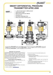
Hazardous area<br />
Safe area<br />
V+ V-<br />
+Ucc<br />
We recommend the <strong>Aplisens</strong><br />
ZL-24-08 power supply,<br />
which can supply up to five<br />
ZS-30EEx1 devices<br />
I<br />
P+<br />
IN<br />
P-<br />
+24V GND<br />
O+<br />
O-<br />
OUT<br />
Ro<br />
Intrinsically safe transmitter<br />
Electrical diagram<br />
VII/ 7
Input parameters<br />
Input signal from the transmitter<br />
Technical parameters<br />
4...20 mA<br />
Supply voltage of the input circuit U IN 15 V 18 V 20 V 22 V 25 V<br />
Maximum voltage on the terminals of the input circuit U 0 15,75 V 18,9 V 21 V 23,1 V 25,5 V<br />
Input voltage after loading by the<br />
transmitter with output signal 4…20 mA U IN20 = U IN [V] · 0,75<br />
U IN is the supply voltage of the input circuit<br />
Maximum shorting current of input circuit<br />
Output parameters<br />
Output signal<br />
I 0 = 100 mA<br />
Output load resistance<br />
4...20 mA 500 <br />
0...20 mA 500 <br />
0...5 mA 2 k<br />
0...5 V, 1...5 V, 0...10 V 10 k<br />
Galvanic separation<br />
IN-OUT<br />
IN-SUPPLY, OUT-SUPPLY<br />
Test voltage between circuits<br />
Conversion errors<br />
Accuracy 0,1%<br />
Non-linearity ±0,05%<br />
Effect of temperature fluctuations ±0,1% / 10°C<br />
Effect of load resistance fluctuations<br />
±0,05%<br />
Effect of supply voltage fluctuations<br />
±0,1%<br />
optoelectronic<br />
pulse transformer<br />
2,5 kV AC, 50 Hz or equivalent DC<br />
Dynamic characteristics<br />
Time constant c. 0,05 s (by arrangement: 0,1...1 s)<br />
Power supply<br />
Supply voltage 24V DC ± 10%<br />
Permitted ripple 1%<br />
Supply current<br />
90 mA<br />
Conditions of normal use<br />
Ambient temperature<br />
5...60°C<br />
Relative humidity 30...80%<br />
Casing<br />
Ingress protection rating<br />
Weight<br />
IP20<br />
0,2 kg<br />
Ordering procedure<br />
Standard version (U = 25 V, output 4...20 mA): ZS-30Ex1<br />
IN<br />
Standard version<br />
Special version: ZS-30Ex1 /___/___<br />
Standard version<br />
Input circuit voltage<br />
Output signal<br />
Important:<br />
For transmitters in version ALW with switched on illumination of display and used internal resistor 250Ù should<br />
be specifed model ZS-30Ex1/24V/25.2V.<br />
VII/ 8