Bull Puppy 2_1 instruction booklet.cdr - Public Missiles Ltd.
Bull Puppy 2_1 instruction booklet.cdr - Public Missiles Ltd.
Bull Puppy 2_1 instruction booklet.cdr - Public Missiles Ltd.

You also want an ePaper? Increase the reach of your titles
YUMPU automatically turns print PDFs into web optimized ePapers that Google loves.
puppy<br />
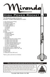
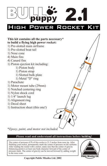
This kit contains all the parts necessary*<br />
to build a flying high power rocket:<br />
1) Pre-slotted main airframe<br />
1) Pre-slotted boat tail<br />
1) Nose cone<br />
4) Main fins<br />
4) Canard fins<br />
1) Piston ejection kit including:<br />
1) Piston body<br />
1) Piston strap<br />
1) Slotted bulk plate<br />
1) Metal "D" ring<br />
1) Parachute<br />
1) Motor mount tube (29mm)<br />
1) Notched centering ring<br />
1) Nylon shock cord<br />
1) 1/4" launch lug<br />
1) Alignment ring<br />
1) Decal sheet<br />
1) Instruction sheet (this one!)<br />
CRADLE<br />
HERE<br />
CRADLE<br />
HERE<br />
AGM-12D<br />
U.S. AIR FORCE<br />
15864211422-01<br />
CENTER SECTION ASM-N-7A<br />
SERIAL NO. AS-3462<br />
ASSEMBLED WITH<br />
EXPLOSIVE LOADED<br />
15864211419-03<br />
15864211422-00<br />
15864211422-02<br />
X-C.G. LOADED<br />
WEIGHT 199 LBS.<br />
*Epoxy, paint, and motor not included.<br />
Please read and understand all <strong>instruction</strong>s before building!<br />
The center of pressure (CP) of this rocket is 21.5 inches from nose tip. After<br />
finishing your rocket, permanently mark the center of pressure on the airframe.<br />
After loading the rocket with a motor, make sure that the center of gravity<br />
(balancing point) is at least one body diameter forward of the center of<br />
pressure mark. The center of gravity can be moved forward by adding weight<br />
to the nose cone.<br />
Copyright <strong>Public</strong> <strong>Missiles</strong> <strong>Ltd</strong>. 2002
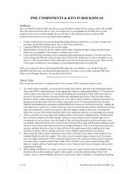
Basic Construction FAQ<br />
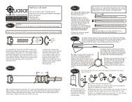
PREP & ASSEMBLY<br />
( Read and understand the <strong>instruction</strong> steps fully before you begin the step.<br />
( The manufacturing process of cutting QT may leave the cut end of a tube “squeezed” slightly so that<br />
nosecones or pistons seem tight when passing through the end of the tube. Chamfer the inside edge of<br />
the tube end via sanding or scraping with a sharp X-Acto knife to prevent this problem.<br />
( ALWAYS sand the parts to be bonded with 100-120 grit sandpaper. This includes the area inside the<br />
QT where the MMT, fins, couplers, etc. will be bonded. Sandpaper flappers on a drill or sandpaper<br />
glued to a dowel work well.<br />
( Sand the fin fillet area on each side of the fin slots with 150 grit sandpaper before applying epoxy to<br />
the fin and tube.<br />
( We strongly recommend you dry-fit (assemble without gluing) all parts in each step BEFORE<br />
epoxying them together. Sand or adjust fit as needed before gluing.<br />
( Most epoxies work fine. Use 5 or 15 minute depending on how quickly you feel you can complete the<br />
step. Use longer set-time epoxy if you're unsure.<br />
( To make internal fillets to the fins deep up into the airframe, "load up" the end of a dowel with a blob<br />
of epoxy, then stick the dowel into the airframe and onto the fin joint you're working on. After<br />
depositing enough epoxy in this fashion, you can pull the dowel toward you, making a fillet with the<br />
rounded edge of the dowel.<br />
( Fins can be "shaped" or just lightly sand the edges to remove any manufacturing burrs.<br />
( PML now advises that CA (cyanoacrylate; “super glue”) adhesives CAN be used with QT, though<br />
epoxy is recommended.<br />
PAINTING/FINISHING<br />
( Before you paint the fins, scuff the entire surface with 220 grit sandpaper. Scuffing is easiest to do<br />
before mounting the fins.<br />
( Before painting the airframe, lightly sand it with 320-400 grit sandpaper.<br />
( Do not wipe or spill lacquer thinner or acetone on the Quantum Tube, either will melt and distort the<br />
tube. Alcohol or mineral spirits will not damage the QT.<br />
( Plastic nosecone imperfections can be filled with plastic model kit putty or automotive spot putty..<br />
( Stay with the same brand of paint throughout the process; primer, base color, accent colors, and clear<br />
coat. Lacquer, enamel, epoxy and urethane paints have been tested and are compatible with QT tubing.<br />
DO NOT skimp on the "shake the can for at least two minutes after the ball rattles" step! For the best<br />
finish, let each coat dry overnight and sand lightly with 320 or 400 grit sandpaper.<br />
( Apply the last color coat as heavy as possible without running or sagging. Let the paint cure for at least<br />
48 hours before handling!<br />
( We recommend a clear coat of some sort to help protect the decals as well as "seal" their edges to help<br />
prevent them peeling off. When using any clear coat, put on only VERY thin, light coats, and wait at<br />
least 5 minutes between coats. The clear coat can damage your decals or paint if you put it on too<br />
heavily or don't wait long enough between coats!<br />
FINAL FITTING/PREPARATIONS FOR FLIGHT<br />
( The piston should be a smooth slip-fit in the airframe; this is critical. Sand the piston as needed so it<br />
can be easily inserted, and pulled out with just a gentle tug on the shock cord. Keep sandpaper in your<br />
range box in case you need to adjust the fit the first few times at the field to deal with differing<br />
temperature and humidity. For cold weather flights and other info, see the FAQ Page on our website at<br />
www.publicmissiles.com.<br />
( Couplers should also be sanded to allow easy separation of the rocket.<br />
( If the coupler or nosecone is too loose, use masking tape to build it up to a good fit. If the nosecone is<br />
too tight, sand the ribs on the shoulder until it fits well. The parts fit properly if the rocket can be held<br />
upside down and gently shaken with nothing moving or coming apart.<br />
( Ejections will leave a black, gritty residue inside the airframe. Occasionally wipe the tube interior with<br />
a damp cloth wrapped around a dowel or broomstick; allow to dry.<br />
( See our website FAQ for information about thrust rings and motor retention. Motor recommendation<br />
information is available on our website on the Specs Page.<br />
www.publicmissiles.com<br />
The PML Web Store and Knowledge Base
Other items you will need:<br />
> Masking tape<br />
> One set of epoxy<br />
> PML Expandable Liquid Foam (optional)<br />
> One sheet each 120 and 220 sandpaper > Wax paper<br />
> Ruler and pencil<br />
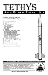
Step 1<br />
Please read and understand all <strong>instruction</strong>s before continuing!<br />
All surfaces to be bonded must be scuffed with 120 grit sandpaper.<br />
NOTE:<br />
The following step must be completed without interruption. Please read and<br />
understand this procedure before continuing.<br />
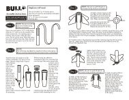
Stand the boat tail upright on a flat surface, preferably on a piece of wax paper. Spread a large<br />
bead of epoxy on the bottom end of the motor mount tube as illustrated. Place the motor mount<br />
tube into the boat tail and press down to make sure the tube is seated flush with the bottom.<br />
Alignment<br />
ring<br />
Centering<br />
ring<br />
Epoxy<br />
Without using any adhesive, immediately place the centering ring over the top of the motor<br />
mount tube and press down firmly until it is in contact with the top of the boat tail. Next slide<br />
the alignment ring over the centering ring, again without adhesive, and press until it is seated<br />
against the boat tail shoulder. Allow to cure. Keep the centering ring and alignment ring in<br />
position while mounting the fins.
Step 2<br />
A) Apply a bead of epoxy to the root edge of a fin. Push the fin through the slot in the airframe<br />
and against the motor mount tube. Make sure that the fin is perpendicular to the airframe. Use<br />
tape to hold the fin in position while the epoxy cures. Repeat this process for all fins.<br />
C) Gently pull the alignment ring<br />
and centering ring off the motor<br />
tube. Using a stick, apply an epoxy<br />
fillet to the fins at the motor mount<br />
tube and the inner airframe wall.<br />
Though not mandatory, a better<br />
method would be to use expandable<br />
liquid foam to encapsulate the entire<br />
fin root area. See the Liquid Foam<br />
<strong>instruction</strong> sheet for details or visit<br />
the Adhesives page of our website at<br />
www.publicmissiles.com.<br />
Step 3<br />
B) Apply an epoxy fillet to both sides of each fin. Carefully smooth the<br />
epoxy with your finger before it begins to gel. Allow the epoxy to set up<br />
before rotating the rocket to do the next set of fins. Once the epoxy has<br />
fully cured, you should sand the fillet smooth with fine sandpaper.<br />
Sanding will help the primer hold better to the epoxy.<br />
Fins not shown for clarity<br />
Epoxy fillet<br />
points<br />
Remove both the alignment ring and the centering ring. Spread a bead of epoxy around the<br />
circumference of the motor tube, 1/2” from the top, leaving a 1” gap in the bead for the notch<br />
in the centering ring. Slip the notched centering ring over the motor tube with the notch<br />
aligned with the gap in the epoxy bead. Be sure the notch in the ring remains clear of epoxy.<br />
Locate the ring 1/2” from the end of the motor tube and allow the epoxy to set. Apply an<br />
epoxy fillet to each side of the ring still keeping the notch clear.<br />
Gap in epoxy<br />
Remove<br />
Alignment<br />
ring<br />
Remove<br />
Centering<br />
ring<br />
Motor tube<br />
Notched<br />
centering ring<br />
Fins not shown for clarity
Step 4<br />
Fins not shown for clarity<br />
Spread a layer of epoxy about 1”<br />
Epoxy<br />
~3.0”<br />
Masking tape<br />
Notch<br />
Piston strap<br />
Fill notch<br />
completely<br />
with epoxy<br />
wide and 3” long on the motor tube<br />
just below the notch in the upper<br />
centering ring. Slip one end of the<br />
piston strap (the widest strap in the<br />
kit) through the notch in the<br />
centering ring. Pull through about<br />
3” of this strap through the notch<br />
and press it firmly into the epoxy<br />
on the side of the motor tube. Hold<br />
the strap in place against the tube<br />
with masking tape until the epoxy<br />
cures. Remove the masking tape.<br />
Fill the entire centering ring<br />
notch with epoxy. Stuff the free<br />
end of the strap into the motor tube<br />
to keep it out of the way for the<br />
next step.<br />
Step 5<br />
1) Apply a bead of epoxy to the<br />
root edge of a fin. Push the fin<br />
through the dado groove in the<br />
airframe. Make sure that the fin<br />
is perpendicular to the airframe.<br />
Use tape to hold the fin in<br />
position while the epoxy cures.<br />
Repeat this process for all fins.<br />
Stuff piston strap into<br />
motor tube to keep it<br />
out of the way for the<br />
next step.<br />
2) Apply an epoxy fillet to both sides<br />
of each fin. Carefully smooth the<br />
epoxy with your finger before it<br />
begins to gel. Allow the epoxy to setup<br />
before rotating the rocket to do the<br />
next set of fins. Once the epoxy has<br />
fully cured, you should sand the fillet<br />
smooth with 180 grit sandpaper.<br />
Sanding will help the primer hold<br />
better to the epoxy.<br />
Step 6<br />
Apply a heavy layer of epoxy to the inside circumference of the main airframe at the bottom end<br />
and another 2” in from the bottom. Push the tail section into the main airframe as shown. Align the<br />
upper and lower fins. Stand the assembly upright and allow the epoxy to cure.<br />
~2.0”<br />
~7.0”<br />
Sand the entire surface of the launch lug with 100 or 120 grit sandpaper. Epoxy the launch<br />
lug into position starting 7” up from the bottom of the main airframe. Be sure the lug is not in<br />
line with the fins and is parallel to the airframe.
Step 7<br />
NOTE: In this step you will be using the free end of the<br />
strap that you mounted to the motor tube assembly.<br />
A B C D<br />
E<br />
F<br />
A) Pull the free end of the strap through the slot in the piston bulk plate.<br />
B) Slip the metal "D" ring over the strap.<br />
C) Feed the strap back through the slot.<br />
D) Pull on the strap until the “D” ring is wedged at the slot.<br />
E) Flip the assembly over. Spread a layer of epoxy on the underside of the piston plate as<br />
shown. Fold the short end of the strap flat<br />
against the piston plate and press it into the<br />
H<br />
epoxy. You can use a clamp to hold the strap<br />
in the epoxy while it sets.<br />
G<br />
F) When the epoxy has cured, pull the strap<br />
until the "D" ring is wedged tight at the slot.<br />
Apply epoxy to the strap at the "D" ring.<br />
G) Epoxy the piston plate inside the piston<br />
body 1/8" from the top.<br />
H) Apply an epoxy fillet to both sides of the<br />
piston plate.<br />
Step 8<br />
In an up-coming step<br />
you will tie the<br />
short end to<br />
the eyelet on<br />
the nosecone<br />
1/3 of shockcord<br />
In the next step<br />
you will tie the<br />
long end to the<br />
“D” ring on<br />
the piston<br />
Prepare the parachute per<br />
the parachute <strong>instruction</strong>s.<br />
Thread the shock cord<br />
through the loop you made<br />
in the parachute shroud lines<br />
and tie it using the knot<br />
illustrated on the left. Note<br />
that the chute should be<br />
attached to the shock cord at<br />
about the 1/3 point of the<br />
shock cord. Alternatively,<br />
you can tie the shock cord to<br />
a “kwik-link” and then<br />
attach the “kwik-link” to the<br />
loop in the shroud lines.
Step 9<br />
Thread the long end of the shock cord through the “D” ring and tie it using the knot illustrated<br />
below. Alternatively, you can tie the shock cord to a “kwik-link” and then attach the “kwiklink”<br />
to the “D” ring.<br />
6.0”<br />
To cinch the knot, alternately<br />
pull on the trailer and push<br />
the knot towards the attach<br />
point. Repeat until tight. To<br />
make sure the knot never<br />
slips, place a drop of epoxy<br />
on the trailer where it meets<br />
the knot. DO NOT saturate<br />
the knot with epoxy or CA!<br />
Pull<br />
trailer<br />
Push<br />
knot<br />
Drop of<br />
epoxy<br />
Step 10<br />
Using a sharp pointed knife, remove the flash from the eyelet at the base of the nosecone.<br />
If<br />
necessary, you can enlarge the eyelet by using the knife to extend the opening toward the<br />
nosecone body (not toward the edges as this will weaken the eyelet.<br />
Thread the shock cord<br />
through the eyelet and tie it to the nosecone using the knot illustrated below. Add a drop of<br />
epoxy to the trailer at the knot to make sure the knot never slips. DO NOT saturate the knot<br />
with epoxy or CA. Alternatively, you can tie the shock cord to a “kwik-link” and then attach<br />
the “kwik-link” to the nosecone eyelet.<br />
6.0”<br />
Drop of<br />
epoxy<br />
When fitting the nosecone to the top of the airframe, it should be just tight enough to allow<br />
you to lift the entire rocket by the tip without the nosecone sliding off the rocket. If the fit<br />
seems too tight, very lightly sand the two ridges on the nosecone shoulder. If the fit seem too<br />
loose, apply small lengths of masking tape to the nosecone shoulder.
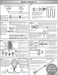
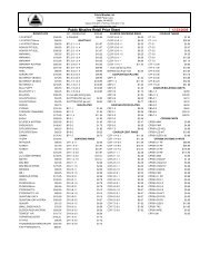
#11<br />
#1<br />
AGM-12D<br />
U.S. AIR FORCE<br />
#9<br />
#10<br />
AGM-12D<br />
U.S. AIR FORCE<br />
X-C.G. LOADED<br />
WEIGHT 199 LBS.<br />
#2<br />
X-C.G. LOADED<br />
WEIGHT 199 LBS.<br />
#7<br />
15864211422-02 #3 15864211422-02<br />
15864211419-03 #4 15864211419-03<br />
#8<br />
#9<br />
#4<br />
15864211422-00<br />
15864211419-03<br />
15864211422-01<br />
CENTER SECTION ASM-N-7A<br />
SERIAL NO. AS-3462<br />
ASSEMBLED WITH #5<br />
EXPLOSIVE LOADED<br />
CRADLE<br />
HERE<br />
CRADLE<br />
HERE<br />
CRADLE<br />
HERE<br />
CRADLE<br />
HERE<br />
15864211422-01<br />
#6<br />
CENTER SECTION ASM-N-7A<br />
SERIAL NO. AS-3462<br />
ASSEMBLED WITH<br />
EXPLOSIVE LOADED COPYRIGHT 2002<br />
15864211422-00 #7 15864211422-00<br />
#8<br />
#5<br />
#9<br />
15864211422-01<br />
CENTER SECTION ASM-N-7A<br />
SERIAL NO. AS-3462<br />
ASSEMBLED WITH<br />
EXPLOSIVE LOADED<br />
Entire rocket<br />
is white<br />
#1<br />
AGM-12D<br />
U.S. AIR FORCE<br />
15864211422-02<br />
#6<br />
#10<br />
CRADLE<br />
HERE<br />
CRADLE<br />
HERE<br />
#3<br />
X-C.G. LOADED<br />
WEIGHT 199 LBS.<br />
#11<br />
#2<br />
www.publicmissiles.com<br />
The PML Web Store and Knowledge Base<br />
Revised 2.7.02