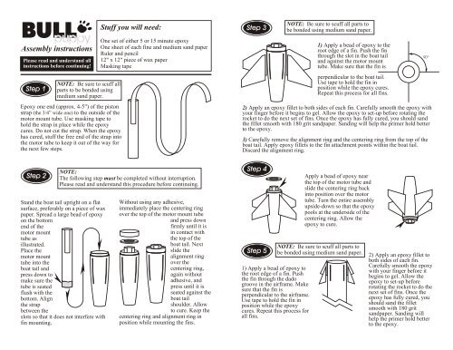
Assembly instructions - Public Missiles Ltd.
Assembly instructions - Public Missiles Ltd.
Assembly instructions - Public Missiles Ltd.

Create successful ePaper yourself
Turn your PDF publications into a flip-book with our unique Google optimized e-Paper software.
<strong>Assembly</strong> <strong>instructions</strong><br />
Please read and understand all<br />
<strong>instructions</strong> before continuing!<br />
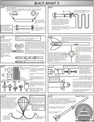
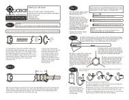
Step 1<br />
NOTE: Be sure to scuff all<br />
parts to be bonded using<br />
medium sand paper.<br />
Epoxy one end (approx. 4-5") of the piston<br />
strap (the 3/4” wide one) to the outside of the<br />
motor mount tube. Use masking tape to<br />
hold the strap in place while the epoxy<br />
cures. Do not cut the strap. When the epoxy<br />
has cured, stuff the free end of the strap into<br />
the motor tube to keep it out of the way for<br />
the next few steps.<br />
Stuff you will need:<br />
One set of either 5 or 15 minute epoxy<br />
One sheet of each fine and medium sand paper<br />
Ruler and pencil<br />
12" x 12" piece of wax paper<br />
Masking tape<br />
Step 3<br />
NOTE: Be sure to scuff all parts to<br />
be bonded using medium sand paper.<br />
1) Apply a bead of epoxy to the<br />
root edge of a fin. Push the fin<br />
through the slot in the boat tail<br />
and against the motor mount<br />
tube. Make sure that the fin is<br />
perpendicular to the boat tail.<br />
Use tape to hold the fin in<br />
position while the epoxy cures.<br />
Repeat this process for all fins.<br />
2) Apply an epoxy fillet to both sides of each fin. Carefully smooth the epoxy with<br />
your finger before it begins to gel. Allow the epoxy to set-up before rotating the<br />
rocket to do the next set of fins. Once the epoxy has fully cured, you should sand<br />
the fillet smooth with 180 grit sandpaper. Sanding will help the primer hold better<br />
to the epoxy.<br />
3) Carefully remove the alignment ring and the centering ring from the top of the<br />
boat tail. Apply epoxy fillets to the fin attachment points within the boat tail.<br />
Discard the alignment ring.<br />
90 o<br />
Step 2<br />
NOTE:<br />
The following step must be completed without interruption.<br />
Please read and understand this procedure before continuing.<br />
Stand the boat tail upright on a flat<br />
surface, preferably on a piece of wax<br />
paper. Spread a large bead of epoxy<br />
on the bottom<br />
end of the<br />
motor mount<br />
tube as<br />
illustrated.<br />
Place the<br />
motor mount<br />
tube into the<br />
boat tail and<br />
press down to<br />
make sure the<br />
tube is seated<br />
flush with the<br />
bottom. Align<br />
the strap<br />
between the<br />
slots so that it does not interfere with<br />
fin mounting.<br />
Without using any adhesive,<br />
immediately place the centering ring<br />
over the top of the motor mount tube<br />
and press down<br />
firmly until it is<br />
in contact with<br />
the top of the<br />
boat tail. Next<br />
slide the<br />
alignment ring<br />
over the<br />
centering ring,<br />
again without<br />
adhesive, and<br />
press until it is<br />
seated against the<br />
boat tail<br />
shoulder. Allow<br />
to cure. Keep the<br />
centering ring and alignment ring in<br />
position while mounting the fins.<br />
Step 4<br />
Step 5<br />
1) Apply a bead of epoxy to<br />
the root edge of a fin. Push<br />
the fin through the dado<br />
groove in the airframe. Make<br />
sure that the fin is<br />
perpendicular to the airframe.<br />
Use tape to hold the fin in<br />
position while the epoxy<br />
cures. Repeat this process for<br />
all fins.<br />
Apply a bead of epoxy near<br />
the top of the motor tube and<br />
slide the centering ring back<br />
into position over the motor<br />
tube. Turn the entire assembly<br />
upside-down so that the epoxy<br />
pools at the underside of the<br />
centering ring. Allow the<br />
epoxy to cure.<br />
NOTE: Be sure to scuff all parts to<br />
be bonded using medium sand paper.<br />
2) Apply an epoxy fillet to<br />
both sides of each fin.<br />
Carefully smooth the epoxy<br />
with your finger before it<br />
begins to gel. Allow the<br />
epoxy to set-up before<br />
rotating the rocket to do the<br />
next set of fins. Once the<br />
epoxy has fully cured, you<br />
should sand the fillet<br />
smooth with 180 grit<br />
sandpaper. Sanding will<br />
help the primer hold better<br />
to the epoxy.
Step 6<br />
Apply a heavy layer of epoxy to the inside circumference of<br />
the main airframe at the bottom end. Push the tail section into<br />
the main airframe as shown. Align the upper and lower fins.<br />
Stand the assembly upright and allow to cure.<br />
Epoxy the launch lug into position starting 3" up from the<br />
bottom of the main airframe. Be sure the lug is not in line<br />
with the fins.<br />
Step 7<br />
A) Pull the free end<br />
of the strap through<br />
the slot in the piston<br />
bulk plate. Slip the<br />
metal "D" ring over<br />
the strap.<br />
The strap referred to in this step is the strap you installed in the<br />
airframe in a previous step.<br />
A<br />
Measure off the mid point of<br />
each parachute shroud line<br />
and mark it with a pen.<br />
Gather all the shroud lines<br />
making sure they are not<br />
twisted or tangled. Keep all<br />
the marks on the shroud lines<br />
together. Tie the lines together<br />
using a simple overhand knot<br />
leaving a small loop where all the<br />
marks meet. Tie the parachute to<br />
the elastic shock cord 1/3 of the<br />
way from one end. Tie the long end<br />
of the shock cord to the "D" ring<br />
on the piston. Tie the<br />
short end of the shock<br />
cord to the eyelet on the<br />
nose cone.<br />
B<br />
B) Feed the strap back through the slot.<br />
C) Flip the assembly over. Fold the short end of the strap<br />
flat against the bulkplate and epoxy in place.<br />
D) When the epoxy has cured, pull the strap until the "D"<br />
ring is wedged at the slot. Apply epoxy to the strap at the<br />
"D" ring.<br />
E) Epoxy the bulkplate to the piston body 1/8" from the<br />
top. Apply an epoxy fillet to both sides of the bulkplate.<br />
Step 8 Step 9<br />
34"<br />
Parachute<br />
C<br />
NOT<br />
E:<br />
When tying the<br />
shock cord to the<br />
parachute and the "D"<br />
ring, loop the shock cord<br />
through twice then tie a<br />
double overhand knot.<br />
Pull the knot tight and<br />
leave a 2-3 inch<br />
trailer.<br />
Copyright 1996<br />
D<br />
E<br />
Slide the piston<br />
into the rocket<br />
followed by the<br />
shock cord and<br />
parachute. Place the nose<br />
cone atop the rocket. It<br />
should fit just tight enough<br />
to allow you to lift the<br />
rocket by the nose cone<br />
without it slipping<br />
off. Wrap masking<br />
tape around the<br />
shoulder of the<br />
nose cone for a<br />
tighter fit if<br />
necessary. Now<br />
install the motor<br />
and go fly your<br />
rocket!<br />
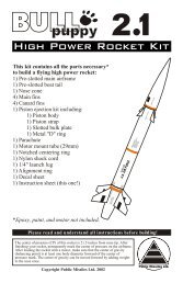
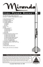
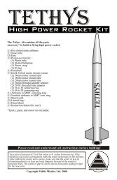
The kit contains all the parts<br />
necessary* to build a flying high power<br />
rocket:<br />
1) Pre-slotted main airframe<br />
1) Pre-slotted boat tail<br />
1) Nose cone<br />
4) Main fins<br />
4) Canard fins<br />
1) Piston ejection kit including:<br />
1) Piston body<br />
1) Piston strap<br />
1) Slotted bulk plate<br />
1) Metal "D" ring<br />
1) Parachute<br />
1) Motor mount tube (38mm)<br />
1) Notched centering ring<br />
1) Elastic shock cord<br />
1) 1/4" launch lug<br />
1) Alignment ring<br />
1) Military<br />
Decal sheet<br />
1) Instruction sheet (this one!)<br />
*Epoxy, paint, and motor not included.<br />
The center of pressure (CP) of this rocket is 28 inches from nose tip. After<br />
finishing your rocket, permanently mark the center of pressure on the airframe.<br />
Calculations made using RockSim 4.0 program for subsonic flights. After<br />
loading the rocket with a motor, make sure that the center of gravity (balancing<br />
point) is 3" forward of the center of pressure mark. The center of gravity can be<br />
moved forward by adding weight to the nose cone. It is impossible to test every<br />
rocket with every motor configuration therefore, if you are unsure about motor<br />
selection for any rocket consult the motor manufacturer.