R&D Engine Mount Catalog.pdf - PYI Inc.
R&D Engine Mount Catalog.pdf - PYI Inc.
R&D Engine Mount Catalog.pdf - PYI Inc.

You also want an ePaper? Increase the reach of your titles
YUMPU automatically turns print PDFs into web optimized ePapers that Google loves.
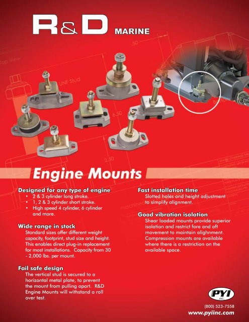
Designed for any type of engine<br />
• 2 & 3 cylinder long stroke.<br />
• 1, 2 & 3 cylinder short stroke.<br />
• High speed 4 cylinder, 6 cylinder<br />
and more.<br />
Wide range in stock<br />
Standard sizes offer different weight<br />
capacity, footprint, stud size and height.<br />
This enables direct plug-in replacement<br />
for most installations. Capacity from 30<br />
- 2,000 lbs. per mount.<br />
Fast installation time<br />
Slotted holes and height adjustment<br />
to simplify alignment.<br />
Good vibration isolation<br />
Shear loaded mounts provide superior<br />
isolation and restrict fore and aft<br />
movement to maintain alighnment.<br />
Compression mounts are available<br />
where there is a restriction on the<br />
available space.<br />
Fail safe design<br />
The vertical stud is secured to a<br />
horizontal metal plate, to prevent<br />
the mount from pulling apart. R&D<br />
<strong>Engine</strong> <strong>Mount</strong>s will withstand a roll<br />
over test.<br />
(800) 523-7558<br />
www.pyiinc.com
Compression <strong>Mount</strong>ings<br />
Rectangular Shear <strong>Mount</strong>ings
Rectangular Shear <strong>Mount</strong>ings<br />
Circular Shear <strong>Mount</strong>ings
Double Acting <strong>Mount</strong>ing<br />
R&D Marine <strong>Engine</strong> <strong>Mount</strong>ings<br />
How To Select (details required)<br />
1. <strong>Engine</strong> type and number of cylinders.<br />
2. Type of gearbox and reduction ratio.<br />
3. Weight of engine and gearbox combined by weighing or manufacturers literature.<br />
4. Is the flywheel in conventional place between the engine and gearbox?<br />
5. Position of the engine mounting points.<br />
6. Find the center of gravity by balancing on a roller (if possible)<br />
7. If the center of gravity cannot be found, assume weight distribution of 60% on rear mounts, with 40% on front mounts (if rear<br />
mount is in line with flywheel).<br />
Installation Details<br />
Maximum clearance between the underside of the height adjusting nut and top washer must not be more than 10mm. If more height<br />
is required use a spacer under the mounting casting. This applies to all mountings in the R&D Marine Range.<br />
Units of measurement: Black = Millimeters Red = <strong>Inc</strong>hes<br />
R&D by <strong>PYI</strong> <strong>Inc</strong>. offers a full line of drive train solutions such as<br />
Split Couplings • Damper Plates • Flexible Shaft Couplings<br />
<strong>PYI</strong> <strong>Inc</strong>. • 12532 Beverly Park Road, Lynnwood, WA 98087 • Tel: 800-523-7558 • Fax:425-355-3661 • Email: info@pyiinc.com • www.pyiinc.com