LRK-1000 Series - General Dynamics SATCOM Technologies
LRK-1000 Series - General Dynamics SATCOM Technologies
LRK-1000 Series - General Dynamics SATCOM Technologies

Create successful ePaper yourself
Turn your PDF publications into a flip-book with our unique Google optimized e-Paper software.
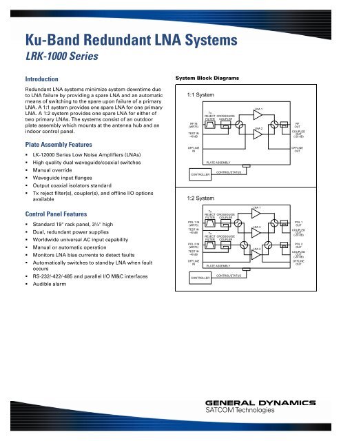
Ku-Band Redundant LNA Systems<br />
<strong>LRK</strong>-<strong>1000</strong> <strong>Series</strong><br />
Introduction<br />
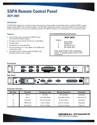
System Block Diagrams<br />
Redundant LNA systems minimize system downtime due<br />
to LNA failure by providing a spare LNA and an automatic<br />
means of switching to the spare upon failure of a primary<br />
LNA. A 1:1 system provides one spare LNA for one primary<br />
LNA. A 1:2 system provides one spare LNA for either of<br />
two primary LNAs. The systems consist of an outdoor<br />
plate assembly which mounts at the antenna hub and an<br />
indoor control panel.<br />
Plate Assembly Features<br />
• LK-12000 <strong>Series</strong> Low Noise Amplifiers (LNAs)<br />
• High quality dual waveguide/coaxial switches<br />
• Manual override<br />
• Waveguide input flanges<br />
• Output coaxial isolators standard<br />
• Tx reject filter(s), coupler(s), and offline I/O options<br />
available<br />
1:1 System<br />
RF IN<br />
(WR75)<br />
TEST IN<br />
-40 dB<br />
OFFLINE<br />
IN<br />
CONTROLLER<br />
1:2 System<br />
Tx<br />
REJECT CROSSGUIDE<br />
FILTER COUPLER<br />
PLATE ASSEMBLY<br />
CONTROL/STATUS<br />
LNA 1<br />
LNA 2<br />
RF<br />
OUT<br />
COUPLED<br />
OUT<br />
(-20 dB)<br />
OFFLINE<br />
OUT<br />
Control Panel Features<br />
• Standard 19" rack panel, 3½" high<br />
• Dual, redundant power supplies<br />
• Worldwide universal AC input capability<br />
• Manual or automatic operation<br />
• Monitors LNA bias currents to detect faults<br />
• Automatically switches to standby LNA when fault<br />
occurs<br />
• RS-232/-422/-485 and parallel I/O M&C interfaces<br />
• Audible alarm<br />
POL 1 IN<br />
(WR75)<br />
TEST IN<br />
-40 dB<br />
POL 2 IN<br />
(WR75)<br />
TEST IN<br />
-40 dB<br />
OFFLINE<br />
IN<br />
CONTROLLER<br />
Tx<br />
REJECT CROSSGUIDE<br />
FILTER COUPLER<br />
Tx<br />
REJECT CROSSGUIDE<br />
FILTER COUPLER<br />
PLATE ASSEMBLY<br />
CONTROL/STATUS<br />
LNA 1<br />
LNA 3<br />
LNA 2<br />
POL 1<br />
OUT<br />
COUPLED<br />
OUT<br />
(-20 dB)<br />
POL 2<br />
OUT<br />
COUPLED<br />
OUT<br />
(-20 dB)<br />
OFFLINE<br />
OUT
System Specifications *<br />
Parameter Notes Min. Nom./Typ. † Max. Units<br />
Frequency Range Band “E” 10.95 12.75 GHz<br />
Band “R” 10.70 12.75 GHz<br />
Noise Temperature, System At +23 °C See Table 1<br />
Versus temperature See Table 2<br />
Gain Standard LNA 60 63 dB<br />
LNA with Option 1 50 53 dB<br />
Gain Match Between LNAs 1 dB<br />
Gain Flatness Full band ±0.5 dB<br />
Per 40 MHz ±0.2 dB<br />
Gain Stability Per day, constant temp ±0.2 dB<br />
Versus temperature -0.04 dB/°C<br />
VSWR Input, standard 1.20 1.25 :1<br />
Input, with system option B,<br />
Tx filter 1.25 1.30 :1<br />
Output 1.20 1.25 :1<br />
Power Output at 1 dB Standard LNA +10 +13 dBm<br />
Compression (P1 dB) LNA with Option 2 +18 +20 dBm<br />
LNA with Option 2 & system<br />
option D, output couplers +17 +19 dBm<br />
Third Order Output Standard LNA +20 +23 dBm<br />
Intercept Point (OIP3) LNA with Option 2 +28 +30 dBm<br />
LNA with Option 2 & system<br />
option D, output couplers +27 +29 dBm<br />
AM/PM Conversion At -5 dBm out 0.05 °/dB<br />
Group Delay per 40 MHz Linear 0.02 ns/MHz<br />
Parabolic 0.002 ns/MHz 2<br />
Ripple 0.2 ns p-p<br />
Maximum Input Power Without damage 0 dBm<br />
Desensitization Threshold for Standard system -20 dBm<br />
13.75–14.50 GHz in With system option B,<br />
Tx filter +30 dBm<br />
Connectors RF Input WR75F Waveguide Flange<br />
RF Output<br />
Type N Female A<br />
Offline In/Out, Coupler In/Out<br />
Type N Female A<br />
Temperature Range Switch Plate Assy -40 +60 °C<br />
* System specifications depend on choice of LNA and various options. Specifications shown are for a typical system<br />
using LK-12000 series LNAs.<br />
†<br />
When there is only one value on a line, the Nom./Typ. column is a nominal value; otherwise it is a typical value.<br />
Typical values are intended to illustrate typical performance, but are not guaranteed.<br />
A<br />
SMA Female connectors available on request (option).
Part Number/Ordering Information<br />
Ku-Band LNA Systems (a) L R K 0 0 0 0 – 0 0 0 0 0 0 0<br />
System Type: 1:1 . . . . . 1<br />
1:2 . . . . . 2<br />
LNA Frequency: 10.95-12.75 GHz E<br />
10.70-12.75 GHz R<br />
LNA Noise Temp.: 65 K (b) . . . . . 6 5<br />
70 K . . . . . . 7 0<br />
80 K . . . . . . 8 0<br />
90 K . . . . . . 9 0<br />
LNA Options: 60 dB gain (standard) . . X<br />
50 dB gain (option) . . . 1<br />
+12 dBm output (standard) . X<br />
+20 dBm output (option) . . 2<br />
System Options: No filter . . . . . . . . . . X<br />
Tx reject filter , -60 dB . . . . B<br />
• 13.75-14.50 GHz reject band<br />
No input coupler(s) . . . . . . X<br />
Input CG coupler(s), -40 dB . . . C<br />
No output coupler (s) . . . . . . X<br />
Output coaxial coupler(s), -20 dB . . D<br />
No offline I/O . . . . . . . . . . . X<br />
Offline I/O, terminated, with isolator . . E<br />
Control Cable: No cable . . . . . . . . . . . . . X<br />
(Standard service) 100 ft. (30 m) . . . . . . . . . . . . 1<br />
150 ft. (45 m) . . . . . . . . . . . . 2<br />
200 ft. (60 m) . . . . . . . . . . . . 3<br />
250 ft. (75 m) . . . . . . . . . . . . 4<br />
Examples:<br />
1:1 system with 10.95-12.75 GHz, 80 K LNAs, no LNA options,<br />
no system options, and 100 ft. cable:<br />
Order Number L R K 1 E 8 0 - X X X X X X 1<br />
1:1 system with 10.70-12.75 GHz, 65 K LNAs (b) , no LNA options,<br />
Tx Reject filter, CG coupler, and 200 ft. cable:<br />
Order Number L R K 1 R 6 5 - X X B C X X 3<br />
1:2 system with 10.95-12.75 GHz, 90 K LNAs with low gain<br />
option, input CG coupler, output coax coupler, offline I/O, and<br />
150 ft. cable:<br />
Order Number L R K 2 E 9 0 - 1 X X C D E 2<br />
1:2 system with 10.70-12.75 GHz, 70 K LNAs with high power<br />
output and low gain options, Tx filter, input and output couplers,<br />
offline I/O, and 250 ft. cable:<br />
Order Number L R K 2 R 7 0 - 1 2 B C D E 4<br />
Notes:<br />
(a) Consult factory for custom configurations.<br />
(b) Consult factory for delivery of 65 K LNAs.<br />
Table 1 — Typical System Noise Temperature with Various Options (Add to T LNA )<br />
System —— 1:1 —— —————— 1:2 ——————<br />
Configuration: Pol. 1 Pol. 2 Standby<br />
Standard Configuration (Add to T LNA ) ........................................... 5 K .............................. 5 K 9 K 14 K<br />
With 40 dB Crossguide Coupler(s) .............................................. 7 K .............................. 7 K 11 K 16 K<br />
With Transmit Reject Filter(s) ...................................................... 18 K ............................. 18 K 22 K 27 K<br />
With Tx Filter(s) and Coupler(s) ................................................... 20 K ............................. 20 K 24 K 29 K<br />
Table 2 — Noise Temperature vs. Ambient Temperature<br />
Noise temperature vs. ambient temperature can be found from the<br />
equation,<br />
NT 2 /NT 1 = (T 2 /T 1 ) n<br />
where:<br />
NT 2 = Noise Temperature at T 2<br />
NT 1 = Noise Temperature at T 1<br />
T 2 = Temperature 2 in K<br />
T 1 = Temperature 1 in K<br />
n = 1.8 for the LNAs or = 1.0 for passive losses<br />
For the case where T 1 = 296 K (+23 °C), the ratio NT 2 /NT 1 is<br />
shown in the table below for both LNAs (n = 1.8) and for passive<br />
losses (n = 1.0):<br />
Ambient Temperature<br />
T 2 (°C)<br />
n = 1.8<br />
NT 2 /NT 1<br />
n = 1.0<br />
NT 2 /NT 1<br />
0 0.86 0.92<br />
+23 1.00 1.00<br />
+40 1.11 1.06<br />
+50 1.17 1.09<br />
+60 1.24 1.13<br />
Example:<br />
For a 1:1 system with Tx filter, crossguide coupler and 80 K LNAs, T LNA = 80 K at +23 °C and passive<br />
losses = 20 K at +23 °C; thus, T SYS = 100 K at +23 °C. What is T SYS at +50 °C?<br />
From the table, NT 2 /NT 1 at 50 °C = 1.17 for the LNAs and 1.09 for the passive losses:<br />
NT 2 = 1.17 x (80 K) + 1.09 x (20 K) = 94 K + 22 K = 116 K at +50 °C.
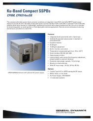
Controller Front Panel (1:1 System):<br />
FAULTS<br />
INPUTS<br />
UNIT 1<br />
OUTPUTS<br />
CONTROLS<br />
1:1 REDUNDANT<br />
SYSTEM CONTROLLER<br />
CONTROLLER<br />
PS 1<br />
ON LINE<br />
CAL<br />
ON LINE<br />
LOCAL<br />
REMOTE<br />
REMOTE PANEL LOCKOUT<br />
RSC-1100<br />
PS 2<br />
RCP<br />
UNIT 2<br />
AUTO<br />
MANUAL<br />
FAULT<br />
RESET<br />
CAL<br />
SHIFT<br />
FUNCTION<br />
ABCDEFGH I<br />
J<br />
PANEL<br />
TEST<br />
OFFLINE<br />
OFFLINE<br />
INC<br />
SETTING<br />
9 8 7 6 5 4 3 2 1 0<br />
DEC<br />
Controller Front Panel (1:2 System):<br />
FAULTS<br />
INPUTS<br />
UNIT 1<br />
OUTPUTS<br />
CONTROLS<br />
1:2 REDUNDANT<br />
SYSTEM CONTROLLER<br />
CONTROLLER<br />
PS 1<br />
POL 1<br />
CAL<br />
UNIT 3<br />
POL 1<br />
LOCAL<br />
REMOTE<br />
REMOTE PANEL LOCKOUT<br />
RSC-1200<br />
PS 2<br />
RCP<br />
POL 2 CAL<br />
UNIT 2<br />
POL 2<br />
AUTO<br />
MANUAL<br />
FAULT<br />
RESET<br />
CAL<br />
SHIFT<br />
FUNCTION<br />
ABCDEFGH I<br />
J<br />
PANEL<br />
TEST<br />
OFFLINE<br />
OFFLINE<br />
INC<br />
SETTING<br />
9 8 7 6 5 4 3 2 1 0<br />
DEC<br />
Controller Rear Panel (All models):<br />
J1<br />
LINE 87-265 V<br />
47-63 Hz<br />
J3<br />
PLATE ASSY<br />
For continued protection against fire,<br />
replace only with same type and rating<br />
of fuse.<br />
Refer servicing to qualified personnel.<br />
PN<br />
CPN<br />
SN<br />
MADE IN U.S.A.<br />
J4<br />
EXT ALM<br />
J5<br />
RCP LINK<br />
J6<br />
LOOP<br />
J7<br />
SERIAL I/O<br />
J8 PARALLEL I/O<br />
J2<br />
!<br />
Consult operation and maintenance<br />
manual for correct fuse rating.<br />
Specifications<br />
Controller<br />
LNA Status Monitor Method<br />
Window Width<br />
Switchover Time<br />
Serial I/O:<br />
Interface<br />
Connector<br />
Parallel I/O:<br />
Status outputs<br />
Control inputs<br />
Connector<br />
Controller Dimensions<br />
Chassis Slides<br />
Control panel monitors LNA bias current. Alarm is generated if current goes outside<br />
of allowed tolerance window.<br />
±5% to ±25% of nominal; software selectable in 5% steps<br />
100 ms<br />
RS-232/RS-422/RS-485 2- or 4-wire<br />
9-Pin D, female<br />
Form ‘C’ dry contacts; 100 Vdc, 0.5 A, 3 W max (resistive load)<br />
Contact closures to ground; withstand 15 V, sink 20 mA<br />
37-pin D, male<br />
19" (483 mm) W x 3.47" (88.1 mm) H x 17.5" (445 mm) D; 25 lb (11.4 kg)<br />
Standard<br />
Cable Length to Plate Assy Order cable separately. 100 ft (30 m) to 500 ft (150 m) lengths in 50 ft (15 m)<br />
increments are standard; other lengths are available by special order.<br />
AC Input<br />
87-265 Vac, 47–63 Hz, 100 W. Dual AC inputs and dual redundant power supplies.<br />
Operating Temperature Range 0 to +50 °C
Front Panel Controls and Indicators<br />
LNA Status Alarms<br />
PS1, PS2 Indicators<br />
Panel Test Pushbutton<br />
Unit Pushbuttons and Indicators<br />
Auto/Manual Switch and Indicators<br />
Remote/Local Switch and Indicators<br />
LED Indicators glow green when OK, red when an LNA fault is detected.<br />
Glow red to show fault with dual redundant power supplies.<br />
Lights all indicators & test audible alarm.<br />
Pushbuttons are used to manually switch the LNAs. Arrow indicators show<br />
which LNAs are switched on-line. Unit indicators light red to show faulted<br />
LNAs. In 1:1 systems, LNA1 is normally the primary LNA and LNA2 is on<br />
standby. In 1:2 systems, LNA1 and LNA2 are the primary LNAs for<br />
Polarization 1 and Polarization 2, respectively. LNA3 is the standby LNA and<br />
can be selected for either polarization.<br />
In Auto mode, an LNA failure initiates automatic switchover to the standby<br />
LNA. In manual mode, the on-line LNA can be selected from the front panel.<br />
Selects either local control, or remote control from serial I/O, parallel I/O, or<br />
remote panel.<br />
Rear Panel I/O Interface<br />
LINE 1 - J1, LINE 2 - J2<br />
TO PLATE ASSEMBLY - J3<br />
Parallel I/O - J8<br />
Serial I/O and Loop - J6 & J7<br />
RCP Link - J5<br />
External Alarm - J4<br />
Dual power entry modules contain the AC line input connector, fuses, and<br />
power switch. System can be powered from separate AC lines if desired.<br />
Either or both power supplies are capable of operating the system.<br />
Cable to antenna plate assembly carries LNA power and switch drive signals.<br />
Order cable separately. Standard lengths are from 100’ (30 m) to 500’ (150 m)<br />
in 50’ (15 m) increments; other lengths are special order.<br />
Parallel I/O connection for customer control or monitoring. Capable of<br />
controlling all features of the system except remote/local switch.<br />
Form ‘C’ relay contact outputs (1:1 systems):<br />
• LNA1 status • PS1 status • Auto/Manual mode<br />
• LNA2 status • PS2 status • Local/Remote mode<br />
• Switch position<br />
Control inputs—contact closure to ground (1:1 systems):<br />
• LNA1 select • LNA2 select • Auto/Manual select<br />
Form ‘C’ relay contact outputs (1:2 systems):<br />
• LNA1 status • PS1 status • Auto/Manual mode<br />
• LNA2 status • PS2 status • Pol. 1: LNA1 or LNA3<br />
• LNA3 status • Local/Remote mode • Pol. 2: LNA2 or LNA3<br />
Control inputs—contact closure to ground (1:2 systems):<br />
• Pol. 1: LNA1 select • Pol. 2: LNA2 select • Auto/Manual select<br />
• Pol. 1: LNA3 select • Pol. 2: LNA3 select<br />
RS-232/RS-422/RS-485 connectors for user M&C System. Commands provide<br />
monitoring, controlling, and configuration.<br />
For optional Remote Control panel, which duplicates all front panel functions.<br />
External Alarm inputs. Substitute for or combine with internal LNA current<br />
monitor alarms. Allows an external signal to indicate LNA failure. Unused<br />
inputs can be used as status inputs to M&C system.
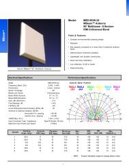
1:1 Plate Assembly Outline Drawing, with Various Options Installed<br />
0.75 [19.0]<br />
OFFLINE INPUT<br />
TYPE N FEMALE<br />
(OPTIONAL)<br />
0.25 [6.3]<br />
WAVEGUIDE<br />
MOUNTING<br />
SURFACE<br />
6.40 [162.6]<br />
LNA 2<br />
3.40 [86.4]<br />
9.00<br />
[228.6]<br />
7.25<br />
[184.2]<br />
S1<br />
LNA 1<br />
W3<br />
OPTIONAL<br />
CROSSGUIDE<br />
COUPLER<br />
OPTIONAL<br />
Tx REJECT<br />
FILTER<br />
0.63 [15.9]<br />
7.25 [184.1]<br />
0.28 x 0.75 SLOT<br />
[7.1 x 19.0]<br />
(4 PLACES)<br />
8.50 [215.9]<br />
11.50 [292.1]<br />
NOTES:<br />
1. OUTPUT ISOLATOR INCLUDED WITH STANDARD SYSTEM.<br />
2. OPTIONAL TRANSMIT REJECT FILTER, CROSSGUIDE COUPLER, OUTPUT<br />
COAXIAL COUPLER AND OFFLINE INPUT/OUTPUT SHOWN.<br />
3. DIMENSIONS ARE IN INCHES [mm].<br />
7.4 [188]<br />
3.50 [88.9]<br />
0.12 [3.2]<br />
TO CONTROL PANEL<br />
TYPE N FEMALE (LOCATED FARSIDE)<br />
OFFLINE OUTPUT - TYPE N FEMALE<br />
(ISOLATOR OPTIONAL)<br />
COUPLED OUTPUT - TYPE N FEMALE<br />
(OPTIONAL)<br />
OUTPUT - TYPE N FEMALE<br />
Outline 12670-2
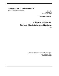
1:2 Plate Assembly Outline Drawing, with Various Options Installed<br />
8.50 [216]<br />
LNA 2<br />
OFFLINE INPUT<br />
TYPE N FEMALE<br />
(OPTIONAL)<br />
LNA 3<br />
0.25 [6.3]<br />
WAVEGUIDE MOUNTING SURFACE<br />
0.75 [19]<br />
6.40 [163]<br />
20.00<br />
[508]<br />
3.40<br />
[86.4]<br />
9.00<br />
[229]<br />
7.25<br />
[184]<br />
POL 1<br />
COUPLED OUT<br />
TYPE N FEMALE<br />
(OPTIONAL)<br />
POL 2<br />
COUPLED OUT<br />
TYPE N FEMALE<br />
(OPTIONAL)<br />
S2<br />
S1<br />
Tx REJECT<br />
FILTERS<br />
(OPTIONAL)<br />
4.50<br />
[114]<br />
POL 1 INPUT<br />
(WR75F)<br />
POL 2 INPUT<br />
(WR75F)<br />
0.28 x 0.75 SLOT<br />
[7.1 x 19.0]<br />
(4 PLACES)<br />
LNA 1<br />
0.62 [16] 7.25 [184]<br />
11.25 [286]<br />
14.6 [372]<br />
NOTES:<br />
1. OUTPUT ISOLATORS INCLUDED WITH STANDARD SYSTEM.<br />
2. OPTIONAL CROSSGUIDE COUPLERS, TRANSMIT REJECT FILTERS, OFFLINE<br />
INPUT/OUTPUT AND COUPLED OUTPUTS SHOWN.<br />
3. DIMENSIONS ARE IN INCHES [mm].<br />
CROSSGUIDE COUPLERS<br />
COUPLED INPUTS - TYPE N FEMALE<br />
(OPTIONAL)<br />
3.00<br />
[76.2]<br />
8.1<br />
[205]<br />
3.50<br />
[88.9]<br />
0.12 [3.2]<br />
0.60 [15]<br />
TO CONTROL PANEL<br />
POL 2 OUTPUT - TYPE N FEMALE<br />
POL 1 OUTPUT - TYPE N FEMALE<br />
OFFLINE OUTPUT - TYPE N FEMALE<br />
(ISOLATOR OPTIONAL)<br />
Outline 12671-3
Other Products<br />
• Low Noise Amplifiers and LNA Systems<br />
• Solid-State Power Amplifiers and SSPA Systems<br />
• <strong>General</strong> Purpose Converters<br />
• Satellite Communications Equipment<br />
• Custom Subsystems<br />
60 Decibel Road, Suite 200 • State College, PA 16801 USA • Tel. 814 238 2700 • FAX 814 238 6589 11841 Rev. E ECR 9215 1/7/09 MSI<br />
Web Site: www.gdsatcom.com/electronics.php<br />
© <strong>General</strong> <strong>Dynamics</strong>. All rights reserved. <strong>General</strong> <strong>Dynamics</strong> reserves the right to make changes to its products and specifications at any time and without notice.<br />
All trademarks indicated as such herein are trademarks of <strong>General</strong> <strong>Dynamics</strong>. All other product and service names are the property of their respective owners.