Satcom-On-the-Move - General Dynamics SATCOM Technologies
Satcom-On-the-Move - General Dynamics SATCOM Technologies
Satcom-On-the-Move - General Dynamics SATCOM Technologies

You also want an ePaper? Increase the reach of your titles
YUMPU automatically turns print PDFs into web optimized ePapers that Google loves.
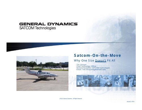
<strong>Satcom</strong>-<strong>On</strong>-<strong>the</strong>-<strong>Move</strong><br />
Why <strong>On</strong>e Size Doesn’t Fit All<br />
Tim Shroyer<br />
Chief Technology Officer<br />
<strong>General</strong> <strong>Dynamics</strong> <strong>SATCOM</strong> <strong>Technologies</strong><br />
Email: Tim.Shroyer@gdsatcom.com<br />
© 2012 <strong>General</strong> <strong>Dynamics</strong>. All Rights Reserved.<br />
January 6, 2012
The fundamental SOTM issue<br />
<strong>Satcom</strong>-<strong>On</strong>-<strong>the</strong>-<strong>Move</strong> <strong>the</strong> systems must be designed to<br />
provide sufficient on-satellite performance while<br />
also generating acceptable levels of Adjacent<br />
Satellite Interference<br />
© 2012 <strong>General</strong> <strong>Dynamics</strong>. All Rights Reserved.<br />
2
The fundamental SOTM issue<br />
The challenge facing all satellite communications systems<br />
Large antennas<br />
radiate adjacent<br />
satellites much less<br />
A satellite system MUST:<br />
• Maximize desired RF radiation<br />
• Minimize undesired RF radiation<br />
• Do both at <strong>the</strong> same time<br />
Additionally, SOTM systems MUST:<br />
• Tolerate shock and vibration<br />
• Do all this <strong>On</strong>-<strong>the</strong>-<strong>Move</strong>!<br />
Small antennas radiate<br />
many satellites<br />
simultaneously<br />
l<br />
This is <strong>the</strong> issue driving all satellite communications systems!<br />
© 2012 <strong>General</strong> <strong>Dynamics</strong>. All Rights Reserved.<br />
3
SOTM regulatory requirements<br />
<strong>Satcom</strong>-<strong>On</strong>-<strong>the</strong>-<strong>Move</strong> <strong>the</strong> systems must satisfy regulatory<br />
requirements for <strong>the</strong> frequency band and<br />
Administration (country) in which <strong>the</strong>y operate<br />
© 2012 <strong>General</strong> <strong>Dynamics</strong>. All Rights Reserved.<br />
4
SOTM links must be designed d differently<br />
<strong>Satcom</strong> system engineers perform a link analysis<br />
• For most satcom systems, <strong>the</strong> main objective is suitable on-satellite performance<br />
• The design objective is suitable link data rate /BER at minimum space segment cost<br />
– This usually means “balanced” use of satellite power and bandwidth<br />
• After link performance is designed, suitable Adjacent Satellite Interference levels are<br />
confirmed<br />
• This same approach is used in satcom and terrestrial links<br />
<strong>Satcom</strong>-<strong>On</strong>-The-<strong>Move</strong> systems are driven by ASI<br />
• Use of smaller antennas results in significant off-axis energy<br />
• Because of this, SOTM link design is a more iterative process<br />
• Adjacent Satellite Interference is usually <strong>the</strong> top concern<br />
• <strong>On</strong>-satellite link performance can be determined after ASI is satisfied<br />
– Meaning it usually requires a series of approximations and trade-offs<br />
<strong>Satcom</strong>-<strong>On</strong>-The-<strong>Move</strong> requires different terminal / space<br />
segment cost trades<br />
• More satellite bandwidth is required to reduce EIRP PSD to acceptable levels<br />
• Most SOTM links use more satellite bandwidth than power (satellite use is not “balanced”)<br />
• Space segment is always ultimately more costly than terminal hardware<br />
• Both can be very significant<br />
• Terminal trade-offs can have a very large impact on space segment cost<br />
© 2012 <strong>General</strong> <strong>Dynamics</strong>. All Rights Reserved.<br />
5
SOTM must meet ASI limits<br />
Uplink interference generated on adjacent satellites is limited<br />
by international agreement (ITU Recommendations) and is<br />
different for different countries<br />
• Some of <strong>the</strong> most significant regulatory limits include:<br />
ITU-R S.524-9 - Maximum permissible levels of off-axis e.i.r.p. density from earth stations in geostationary-satellite<br />
orbit networks operating in <strong>the</strong> fixed satellite service transmitting in <strong>the</strong> 6 GHz, 13 GHz, 14 GHz and 30 GHz frequency<br />
bands<br />
ITU-R S.728-1 - Maximum permissible level of off-axis e.i.r.p. density from very small aperture terminals (VSATs)<br />
• In <strong>the</strong> United States for civil satcom:<br />
FCC Regulation 25.226 - Blanket Licensing provisions for domestic, U.S. Vehicle-Mounted Earth Stations<br />
(VMESs) receiving in <strong>the</strong> 10.95-11.2 GHz (space-to-Earth), 11.45-11.7 GHz (space-to-Earth), and 11.7-12.2 GHz (space-<br />
to-Earth) frequency bands and transmitting in <strong>the</strong> 14.0-14.5 GHz (Earth-to-space) frequency band, operating with<br />
Geostationary Satellites in <strong>the</strong> Fixed-Satellite Service.<br />
FCC Regulation 25.222 - Blanket Licensing provisions for Earth Stations on Vessels (ESVs) receiving in <strong>the</strong><br />
10.95–11.2 GHz (space-to-Earth), 11.45–11.7 GHz (space-to-Earth), 11.7–12.2 GHz (space-to-Earth) frequency bands<br />
and transmitting in <strong>the</strong> 14.0–14.5 GHz (Earth-to-space) frequency band, operating with Geostationary Orbit (GSO)<br />
Satellites in <strong>the</strong> Fixed-Satellite Service.<br />
• For DoD satcom:<br />
Mil-Std-188-164B – Interoperability of SHF Satellite Communications Terminals<br />
SOTM links must be designed to operate within <strong>the</strong> appropriate ASI<br />
limits i for <strong>the</strong> band and country in which h operations are conducted<br />
d<br />
© 2012 <strong>General</strong> <strong>Dynamics</strong>. All Rights Reserved.<br />
6
SOTM must meet ASI limits<br />
Comparison of <strong>the</strong> various ASI regulations is appropriate<br />
• Adjacent Satellite Interference (ASI) levels are based on EIRP power spectral<br />
density, not total power<br />
• For FSS Ku-Band, <strong>the</strong> levels permitted in <strong>the</strong> United States are lower than in o<strong>the</strong>r<br />
world regions<br />
• Mostly because satellites are spaced every 2 degrees over CONUS<br />
20<br />
Ku-Band EIRP Spectral Density Limits<br />
dBw/4 kH Hz<br />
15<br />
10<br />
5<br />
0<br />
-5<br />
-10<br />
ITU S.524-9<br />
ITU S.728-1<br />
FCC VMES<br />
-15<br />
-20<br />
-25<br />
0 10 20 30 40 50 60 70 80 90 100 110 120 130 140 150 160 170 180<br />
Degrees Azimuth<br />
<strong>On</strong> o<strong>the</strong>r bands, EIRP Density levels are generally higher and driven by international treaty<br />
© 2012 <strong>General</strong> <strong>Dynamics</strong>. All Rights Reserved.<br />
7
SOTM Operational Trade-Offs<br />
<strong>Satcom</strong>-<strong>On</strong>-<strong>the</strong>-<strong>Move</strong> <strong>the</strong> systems must simultaneously satisfy<br />
several different constraints, leading to a number of<br />
operational trade-offs<br />
© 2012 <strong>General</strong> <strong>Dynamics</strong>. All Rights Reserved.<br />
8
SOTM is affected by downlink aperture size<br />
<strong>On</strong> <strong>the</strong> downlink, smaller antennas require more satellite<br />
transponder power and bandwidth for all services<br />
• Different ent satellites have different ent downlink EIRP capabilities<br />
• Satellite downlink EIRP is always limited to some level to avoid interference with<br />
o<strong>the</strong>r systems<br />
• Using different waveforms or modulation characteristics, we can design links to<br />
operate with different size antennas<br />
• The smallest size which can be used can be determined with a link analysis<br />
– It will be driven by <strong>the</strong> possible S/N to support <strong>the</strong> selected modem<br />
– Ultimately. it is limited by satellite EIRP and modem required Eb/No<br />
• Larger antennas will be more efficient in <strong>the</strong> use of satellite power and bandwidth, but<br />
smaller antennas can still be utilized for some links<br />
• The impact of this can be observed on <strong>the</strong> required downlink EIRP graph<br />
Satellite Downlink Power in dBW for 1 MBPS BPSK<br />
40<br />
35<br />
Smaller apertures<br />
require more power<br />
Satellite Downlink EIRP (dB dBW)<br />
30<br />
25<br />
20<br />
15<br />
10<br />
C Dow n EIRP<br />
X Global Dow n EIRP<br />
X Spot Dow n EIRP<br />
Ku Dow n EIRP<br />
Ka Dow n EIRP<br />
5<br />
0<br />
0.3 0.4 0.5 0.6 1 1.2 1.8 2.4 3.8 4.8 6.3 7.3 8.1 9 11 13 16.4 18.3 21<br />
Downlink Antenna Aperture (Meters)<br />
© 2012 <strong>General</strong> <strong>Dynamics</strong>. All Rights Reserved.<br />
9
SOTM is dramatically affected by <strong>the</strong> receive terminal<br />
Satellites have improved<br />
• Now have more EIRP, better G/T in all bands<br />
• This supports smaller antennas<br />
• Smaller antennas still take more power<br />
15<br />
Affects network architecture 10<br />
• SOTM peer-to-peer is difficult<br />
• Best efficiency achieved operating like<br />
VSATs<br />
Satellite Downlink EIRP (dBW)<br />
S<br />
40<br />
35<br />
30<br />
25<br />
20<br />
5<br />
Satellite Downlink Power in dBW for 1 MBPS BPSK<br />
C Dow n EIRP<br />
X Global Dow n EIRP<br />
X Spot Dow n EIRP<br />
Ku Dow n EIRP<br />
0<br />
0.3 0.4 0.5 0.6 1 1.2 1.8 2.4 3.8 4.8 6.3 7.3 8.1 9 11 13 16.4 18.3 21<br />
Downlink Antenna Aperture (Meters)<br />
Ka Dow n EIRP<br />
In most bands ~3.8 M is good<br />
for hub terminals<br />
55<br />
• Downlink power needed by larger antennas<br />
does not go down because Noise is <strong>the</strong>n<br />
dominated by satellite, not earth station G/T<br />
50<br />
• C-Band still typically needs larger antennas<br />
• Mostly limited by terrestrial interference<br />
RP (dBW)<br />
Required EIR<br />
65<br />
60<br />
45<br />
40<br />
35<br />
Required Uplink EIRP in dBW for 1 MBPS BPSK<br />
C Up EIRP<br />
X Global Up EIRP<br />
X Spot Up EIRP<br />
Ku Up EIRP<br />
Ka Up EIRP<br />
30<br />
0.3 0.4 0.5 0.6 1 1.2 1.8 2.4 3.8 4.8 6.3 7.3 8.1 9 11 13 16.4 18.3 21<br />
Downlink Antenna Aperture (Meters)<br />
© 2012 <strong>General</strong> <strong>Dynamics</strong>. All Rights Reserved.<br />
10
SOTM uplink aperture size and pointing drive efficiency<br />
Relatively larger antennas operate like VSATs<br />
• In FSS Ku-Band this happens with effective apertures about 60 cm<br />
• The reason is that suitable on-satellite gain is available to utilize normal waveforms<br />
and still satisfy ASI constraints<br />
Smaller antennas require modulation changes<br />
• ASI limits become <strong>the</strong> dominant factor<br />
• In Ku and Ka-band, improved modem modulation and FEC can satisfy link and ASI<br />
requirements for mid-sized SOTM terminals<br />
• A 50 cm or larger terminal with optimal pointing can satisfy link requirements on most<br />
CONUS satellites using BPSK R-1/2 LDPC modulation<br />
• EIRP PSD limits are higher outside <strong>the</strong> United States<br />
• For <strong>the</strong> smallest SOTM terminals, <strong>the</strong>re is no o<strong>the</strong>r option than to implement some<br />
form of spectrum spreading<br />
• Can be achieved via FEC, spread spectrum, or a combination of both<br />
Reduced pointing accuracy has <strong>the</strong> same link impact as<br />
reduced antenna size<br />
• Reduces on-satellite gain<br />
• Increases ASI levels<br />
© 2012 <strong>General</strong> <strong>Dynamics</strong>. All Rights Reserved.<br />
11
Ku-band close-in EIRP density example<br />
30.0<br />
25.0<br />
20.0<br />
EIRP Density in 4 KHz<br />
18" Dish<br />
FCC VMES<br />
20" Dish<br />
24" Dish<br />
30" Dish<br />
15.0<br />
BW/4KHz<br />
EIRP Density, d<br />
10.0<br />
5.0<br />
0.0<br />
-5.0<br />
-10.0<br />
0 1 2 3 4 5 6 7 8<br />
ANGLE, deg<br />
© 2012 <strong>General</strong> <strong>Dynamics</strong>. All Rights Reserved.<br />
12
SOTM uplink aperture size and pointing drive efficiency<br />
Consider a relatively large SOTM terminal with degraded<br />
pointing<br />
• Larger antenna provides more gain on satellite<br />
• Reduced pointing accuracy imposes significant ASI constraints<br />
30<br />
EIRP Density in 4 KHz)<br />
25 FCC VMES<br />
30" Dish w/ 1 Deg. Error<br />
20<br />
15<br />
1 Degree error results in<br />
> 10 dB gain reduction<br />
required for ASI<br />
30" Dish<br />
Density, dBW/4KHz<br />
EIRP<br />
10<br />
5<br />
0<br />
-5<br />
-10<br />
0 1 2 3 4 5 6 7 8<br />
ANGLE, deg<br />
© 2012 <strong>General</strong> <strong>Dynamics</strong>. All Rights Reserved.<br />
13
SOTM uplink aperture size and pointing drive efficiency<br />
Consider <strong>the</strong> off-boresight gain effects using a flat array<br />
• When satellite is 90 Degrees relative to array face, gain is maximized<br />
• As angle from array approaches zero, gain approaches zero<br />
Gain Decrease<br />
-1<br />
Towards Satellite<br />
-4<br />
-7<br />
-10<br />
-13<br />
Maximum gain on<br />
boresight, perpendicular<br />
to array<br />
Gain reduction in dB<br />
-16<br />
-19<br />
Radiation<br />
Angle<br />
-22<br />
90 85 80 75 70 65 60 55 50 45 40 35 30 25 20 15 10 5<br />
Radiation Angle in Degrees<br />
Array Surface<br />
Angle is actually a three-<br />
dimensional i angle so problem<br />
includes azimuth and elevation<br />
© 2012 <strong>General</strong> <strong>Dynamics</strong>. All Rights Reserved.<br />
14
Cost also drives SOTM terminal trades<br />
Costs include both terminal procurement and space segment costs<br />
Larger antennas have advantages and disadvantages<br />
• Advantages include<br />
• Lower satellite transponder costs<br />
• Improved overall efficiency<br />
• Supports higher data rates<br />
• Disadvantages include<br />
• More expensive to produce due to size and tracking system<br />
• Must be tracked accurately<br />
• “Looks big!”<br />
• Can be too large to mount effectively<br />
Smaller antennas have advantages and disadvantages<br />
• Advantages include<br />
• Lower procurement costs<br />
• Easier to track<br />
• Improved vehicle profile<br />
• Disadvantages include<br />
• Lower efficiency, always resulting in higher satellite costs<br />
• Can be too small to support desired data rate<br />
© 2012 <strong>General</strong> <strong>Dynamics</strong>. All Rights Reserved.<br />
15
Size, weight, and power drive SOTM terminal trades<br />
SWAP comes into play because it is not possible to supply arbitrarily<br />
high data rate services with an exceptionally small terminal<br />
SWAP is driven by vehicle constraints and service requirements<br />
• Some vehicles simply cannot tolerate higher size, weight, or power<br />
• Airborne vehicles especially<br />
• Many land vehicles as well<br />
• Always important for “target profile”<br />
• High data rate services cannot be provided by exceptionally small terminals<br />
• Ultimately limited by combined satellite power and bandwidth<br />
– Per <strong>the</strong> Shannon-Hartley Theorem– finite limits in channel capacity for power and bandwidth<br />
• As aperture size decreases, more bandwidth is required to provide sufficient i satellite power<br />
The “optimal trade” depends upon several factors<br />
• The usual considerations of “cost” and “data rate” are only part of <strong>the</strong> equation<br />
• Vehicle constraints can often be <strong>the</strong> most significant drivers<br />
• This range of factors directly results in <strong>the</strong> need for multiple terminal types<br />
• There will always be a need for “<strong>the</strong> smallest possible”<br />
• However, <strong>the</strong>re is a demonstrated need for “<strong>the</strong> highest data rate”<br />
– Which leads to <strong>the</strong> need for several intermediate options<br />
© 2012 <strong>General</strong> <strong>Dynamics</strong>. All Rights Reserved.<br />
16
Conclusion<br />
<strong>Satcom</strong>-<strong>On</strong>-<strong>the</strong>-<strong>Move</strong> has already resulted in <strong>the</strong> need for<br />
a number of different terminal types and options.<br />
Even as fur<strong>the</strong>r advancements are achieved, no single<br />
option promises to meet <strong>the</strong> complete range of evolving<br />
requirements.<br />
© 2012 <strong>General</strong> <strong>Dynamics</strong>. All Rights Reserved.<br />
17