Lab-14 (Projectile Motion II Range and Alitude
Lab-14 (Projectile Motion II Range and Alitude
Lab-14 (Projectile Motion II Range and Alitude

Create successful ePaper yourself
Turn your PDF publications into a flip-book with our unique Google optimized e-Paper software.
<strong>Lab</strong>-<strong>14</strong>-(<strong>Projectile</strong> <strong>Motion</strong> <strong>II</strong>).doc Rev. 2/18/2006<br />
Name: ____________________________________________ Period: ______ Due Date: _____________<br />
<strong>Lab</strong> Partners: _________________________________________________ Launcher Icon: ___________<br />
<strong>Projectile</strong>s <strong>II</strong> - <strong>Range</strong> & Altitude of <strong>Projectile</strong> WebAssign<br />
Purpose: To investigate the mathematical description of two-dimensional projectile motion.<br />
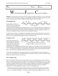
Theory: All projectiles follow a parabolic path because the force of gravity accelerates the motion in<br />
the vertical dimension downward while the horizontal motion exhibits a constant velocity. We<br />
separate these two motions into independent horizontal <strong>and</strong> vertical equations. (It’s like the graph of<br />
x 2 vs x. We are plotting ½at 2 vs t, but it is exactly the same concept; you get a parabola in both cases.)<br />
The general idea is to treat the vertical motion <strong>and</strong> horizontal motion separately; like two components<br />
of a vector. Work only with one component at a time. The common thread that synchronizes them is<br />
the time. Frequently, solving both equations for time <strong>and</strong> then setting the time-independent parts<br />
equal to each other allows us to eliminate time from our calculations. When time is not in the<br />
equation, we don’t have to measure the duration of the flight.<br />
Horizontal <strong>Motion</strong> Equations:<br />
Vertical <strong>Motion</strong> Equations:<br />
a = 0 g = −9.795 m/sec 2 (Local value of g)<br />
<strong>Range</strong> = x−x o = v xo t Altitude = y−y o = v yo t + ½ g t 2<br />
v xo = v muzzle cos θ<br />
v yo = v muzzle sin θ<br />
The difficult part about removing time from these equations is that pesky quadratic term in the<br />
Altitude equation. The general solution requires use of the quadratic formula, which we would like to<br />
avoid at almost any cost. We begin by looking for simplifying conditions.<br />
For example, if the launch is horizontal, then θ = 0 <strong>and</strong> sin θ = 0, so v yo = 0, also. In that case the<br />
Altitude equation is much easier to use (because there is no initial vertical component of velocity) <strong>and</strong><br />
finding the time involves merely taking the square root; not solving a quadratic equation. Thus,<br />
Altitude = y−y o = ½ g t 2<br />
<strong>Range</strong> = x−x o = v xo t<br />
<strong>and</strong><br />
<strong>and</strong><br />
t = [2 (y−y o ) / g] 1/2 t = [(x−x o ) / v xo ]<br />
Upon algebraically solving both the <strong>Range</strong> <strong>and</strong> Altitude equations for t, we can set the right sides of<br />
these two expressions equal to each other to get<br />
(x−x o )/ v xo = [2 (y−y o ) / g] 1/2 (Equation 1)<br />
This case is discussed more thoroughly in the Theory Section for Part I. In the Theory Section for<br />
Part <strong>II</strong> you will learn how to h<strong>and</strong>le these equation when the launch is not horizontal.<br />
Page 1 of 8<br />
02/18/2006
<strong>Lab</strong>-<strong>14</strong>-(<strong>Projectile</strong> <strong>Motion</strong> <strong>II</strong>).doc Rev. 2/18/2006<br />
Theory Section for Part I. Here we consider only the case where a projectile is launched<br />
horizontally, thus<br />
v yo = v muzzle sin θ = 0, because θ = 0.<br />
Therefore,<br />
vertical displacement = y−y o = ½ g t 2 = ½ (−9.795) t 2 = −4.8975 t 2 .<br />
The vertical displacement will always be negative in this case. That simply means the projectile l<strong>and</strong>s<br />
below the launch height. The time needed to drop from rest (There is no initial vertical component of<br />
velocity when the projectile is launched horizontally.) through the specified vertical displacement is<br />
t = [(y−y o )/(−4.8975)] 1/2 = [(−launch altitude)/(−4.8975)] 1/2 = [(launch altitude)/(4.8975)] 1/2<br />
Both the numerator <strong>and</strong> denominator in the ratio are negative numbers, so we can just a well treat the<br />
negative vertical displacement as a positive launch altitude <strong>and</strong> divide it by +4.8975, as shown.<br />
Plugging this expression for time into the <strong>Range</strong> equation (range in this case means distance to the point<br />
where the altitude equals zero) yields (recognizing that v muzzle = v xo , because the projectile is launched<br />
horizontally).<br />
<strong>Range</strong> = x−x o = v xo [(y−y o )/(−4.8975)] 1/2 = v muzzle [(launch altitude)/(4.8975)] 1/2<br />
Notice that we exerted some effort to eliminate the time from this equation. It simplifies our<br />
measurements in that we will not need to measure the time it takes the projectile to reach the point<br />
where its altitude is zero. If all we really want to know is the muzzle velocity, v muzzle , the all we<br />
need to measure are two distances, the launch altitude <strong>and</strong> the range. In other words, the only tool<br />
we need in order to make our measurements is a meter stick or tape measure.<br />
After solving the relevant range equation for the muzzle velocity, we can use the measured launch<br />
altitude <strong>and</strong> the measured range to find the muzzle velocity of the launcher.<br />
v muzzle = (x−x o )[(−4.8975)/( y−y o )] 1/2 = (<strong>Range</strong>) [(4.8975)/(launch altitude)] 1/2<br />
This equation offers an alternative method to the two-step method outlined on the next page in Part I<br />
of the experimental procedures. This method avoids the intermediate time calculation. You should<br />
use this method to confirm the results of Part I after following the two-step method adopted in the<br />
experimental section of Part I.<br />
Page 2 of 8<br />
02/18/2006
<strong>Lab</strong>-<strong>14</strong>-(<strong>Projectile</strong> <strong>Motion</strong> <strong>II</strong>).doc Rev. 2/18/2006<br />
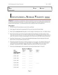
Experimental Procedure<br />
Part I: Finding the Muzzle Velocity of the Launcher using a Horizontal Launch.<br />
1. Fire the ball horizontally (at 0º relative to the horizon) <strong>and</strong> l<strong>and</strong> it on the tabletop. Use<br />
the medium (middle) setting on the launcher. Find a consistent value for the range,<br />
(x−x o ). Be extra careful with this step.<br />
2. Record the initial height of the ball above the tabletop’s l<strong>and</strong>ing elevation, −(y−y o ).<br />
3. Record the horizontal distance of the flight of the ball, (x−x o ).<br />
4. Repeat two or three times until a consistent distance (x−x o ) is obtained.<br />
Enter the range <strong>and</strong> altitude of you projectile along with the numerical results of the<br />
following calculations into the appropriate blanks at the bottom of this page. Answer<br />
each discussion question in the blank section following the question.<br />
5. Calculate the drop time using (y−y o ) = ½ g t 2 .<br />
Q1: Where does this equation come from?<br />
Q1: __________________________________________________________________________________<br />
______________________________________________________________________________________<br />
______________________________________________________________________________________<br />
6. Calculate the horizontal component of the initial velocity, v xo , using the range<br />
equation, x−x o = v xo t. (In our experimental arrangement v muzzle = v xo <strong>and</strong> v yo = 0.<br />
Q2: a) Why is it true to say that v muzzle = v xo<br />
Q2:a) ________________________________________________________________________________<br />
______________________________________________________________________________________<br />
Q2: b) Why is it true that v yo = 0?)<br />
Q2:b) ________________________________________________________________________________<br />
______________________________________________________________________________________<br />
Data: Drop Height = (y−y o ) = _________ m Measured <strong>Range</strong>: x−x o = ___________ m<br />
Calculations: drop time = t = _________ s v xo = v muzzle = _______________ m/s<br />
7. Enter your Part I-value of v muzzle into the Data <strong>and</strong> Results Table on the last page.<br />
Page 3 of 8<br />
02/18/2006
<strong>Lab</strong>-<strong>14</strong>-(<strong>Projectile</strong> <strong>Motion</strong> <strong>II</strong>).doc Rev. 2/18/2006<br />
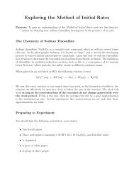
Theory Section for Part <strong>II</strong>. If we consider only projectiles that are launched <strong>and</strong> l<strong>and</strong> at the same<br />
altitude, then y−y o = 0. Solving the altitude equation for time in this particular circumstance yields:<br />
2v<br />
y 0 2vmuzzle<br />
sinθ<br />
2v<br />
t = − = −<br />
=<br />
g g<br />
muzzle<br />
sinθ<br />
g<br />
Substituting this expression for time into the range equation yields the <strong>Range</strong>(v muzzle , θ ):<br />
⎡2v<br />
sinθ<br />
⎤<br />
g ⎥⎦<br />
⎡v<br />
2<br />
( 2θ<br />
)<br />
Equation <strong>II</strong><br />
muzzle<br />
muzzle<br />
<strong>Range</strong> = v cosθ =<br />
Equation <strong>II</strong>I<br />
muzzle ⎢ ⎥ ⎢<br />
⎥ [ Note:<br />
2sinθ<br />
cosθ<br />
= sin(2θ<br />
)]<br />
⎢⎣<br />
⎢⎣<br />
sin<br />
g<br />
This form of the range equation predicts that the maximum range occurs at a launch angle of 45º. At<br />
angles smaller than 45º the projectile falls short because it flies too low. At angles greater than 45º<br />
the projectile falls short because it flies too high. This conclusion assumes that air resistance is not a<br />
factor affecting the flight of the projectile. Our equations model projectiles that fly at low speeds<br />
where air resistance has a negligible influence. The motion of baseballs, golf balls <strong>and</strong> other objects<br />
that travel at high speed are not well described by the range equations derived here.<br />
Experimental Procedure<br />
Part <strong>II</strong>: Finding the Muzzle Velocity of the Launcher using a Variety of Launch Angles.<br />
⎤<br />
⎥⎦<br />
General Instructions:<br />
1. Place a pile of books on the table so that the top of the books is level with the bottom of the ball in<br />
the launch position. (Note: the position of ball in the launch position is printed on the side of the<br />
launcher for your convenience.)<br />
2. Carefully set the cannon at the correct launch angle <strong>and</strong> fire the ball. Find the approximate<br />
position of the l<strong>and</strong>ing zone at the same altitude as the launch altitude. Move the pile of<br />
books to the correct location for a l<strong>and</strong>ing.<br />
3. Fire the ball a second time <strong>and</strong> measure the horizontal distance from the launch position to the<br />
point where the ball l<strong>and</strong>ed on top of the books.<br />
4. Record the horizontal distance the ball traveled in the Data <strong>and</strong> Results Table on the last page.<br />
5. Repeat the procedure for the other angles indicated in the data table. (Note: Because the l<strong>and</strong>ing<br />
zones should be nearly the same, it is highly recommended that you measure the complementary<br />
launch angles in the order listed in the table: 80º then 10º; 70º then 20º; 60º then 30º; etc.)<br />
Page 4 of 8<br />
02/18/2006
<strong>Lab</strong>-<strong>14</strong>-(<strong>Projectile</strong> <strong>Motion</strong> <strong>II</strong>).doc Rev. 2/18/2006<br />
Part <strong>II</strong>: continued<br />
Create Graph I<br />
Before making the calculations in the Data <strong>and</strong> Results Table, you must first construct a graph of<br />
<strong>Range</strong> vs θ. In Graphical Analysis, begin by entering the launch angles in the first column, in the<br />
order they appear in the data table. In the second column enter the range you measured for each<br />
angle. In the File menu select Settings for Untitled <strong>and</strong> Degrees, to simplify the trigonometric<br />
calculations used later. Turn off the connecting lines.<br />
According to Equation <strong>II</strong>I, the range should be proportional the sine of 2θ. That means it will cross<br />
the horizontal axis at 0º <strong>and</strong> 90º, <strong>and</strong> will reach its peak at 45º. Make sure all the data points from 0º<br />
to 90º, including the peak, are visible on your Graph. Fit the data to the following defined function,<br />
(V^2)*sin(2*x)/9.795<br />
When you use the Define Function button you must not use quotation marks, so in this equation the x<br />
refers to θ, because θ is plotted on the horizontal axis; Make sure the column you named Theta has<br />
the short name, x. In this equation V is the only unknown parameter. Graphical Analysis will find<br />
the best value of V that fits the data. Ignore the negative sign of V, if you get one; it is due to a quirk<br />
in the software. Since V = v muzzle , this graph gives you a second estimate for the muzzle velocity.<br />
Enter this graphical value of v muzzle into the Data <strong>and</strong> Results Table on the last page.<br />
Create Graph <strong>II</strong><br />
Before making the calculations in the Data <strong>and</strong> Results Table, you must also construct a graph of<br />
<strong>Range</strong> vs sin (2θ). In the Data menu create a new “calculated” column <strong>and</strong> use it to compute sin (2θ).<br />
In the page menu add a new page, which is a copy of the current page. Graph I will be on page I <strong>and</strong><br />
Graph <strong>II</strong> will be on page <strong>II</strong>. In Graph <strong>II</strong>, graph the range on the vertical axis <strong>and</strong> sin (2θ) on the<br />
horizontal axis.<br />
According to Equation <strong>II</strong>I, this graph should be a straight line through the origin. Fit this line to the<br />
defined function<br />
V^2*x/9.795<br />
This will give you a third estimate of v muzzle since V = v muzzle . Enter this value of v muzzle into the<br />
Data <strong>and</strong> Results Table on the last page.<br />
Which of the three estimates of muzzle velocity does the best job of fitting the range data in the Data<br />
<strong>and</strong> Results Table? (Is there a best choice in your case? If so, which? If not, why not?)<br />
______________________________________________________________________________________<br />
______________________________________________________________________________________<br />
______________________________________________________________________________________<br />
Page 5 of 8<br />
02/18/2006
<strong>Lab</strong>-<strong>14</strong>-(<strong>Projectile</strong> <strong>Motion</strong> <strong>II</strong>).doc Rev. 2/18/2006<br />
Theory Section for Part <strong>II</strong>I. If you wish to consider the general projectile motion problem, then<br />
we would probably want to know both the x <strong>and</strong> y positions as functions of time. These are given on<br />
page 1, thus<br />
(x, y)= (v xo t, y o + v yo t + ½ g t 2 ) = (v muzzle (cos θ ) t, y o + v muzzle (sin θ ) t − 4.8975 t 2 )<br />
Given a series of times, you could easily use Graphical Analysis to calculate the x <strong>and</strong> y coordinates<br />
<strong>and</strong> plot these pairs of coordinates on an xy-graph.<br />
Experimental Procedure<br />
Part <strong>II</strong>I: Calculating the <strong>Range</strong> <strong>and</strong> Maximum Height of the Trajectories.<br />
Calculations:<br />
1. Calculate the range of the projectile at each launch angle using the range equation (Equation <strong>II</strong>I)<br />
with all three of your estimates of v muzzle .<br />
2. Find the percent difference in your experiment between the calculated <strong>and</strong> measured range at each<br />
angle. Use the calculated range as the reference value.<br />
%Difference = 100% x absolute value [(calculated range - measured range) / calculated range]<br />
3. The maximum projectile height at each launch angle can be calculated using<br />
v yo = v muzzle sin θ <strong>and</strong> v y 2 = v yo 2 + 2 g (y−y o )<br />
Remember that v y = 0 at the top of the arc <strong>and</strong> that g = −9.795 m/s 2 at all points along the<br />
trajectory. This means that (y−y o ) = (y−y o ) MAX when v y = 0.<br />
4. Solve these two equations for (y−y o ) MAX , <strong>and</strong> write the equation for the maximum height of the<br />
projectile along its parabolic trajectory as a function of the muzzle velocity <strong>and</strong> the launch angle.<br />
(Derive the equation you will use <strong>and</strong> write it here.)<br />
( y−yo) = MAX<br />
___________________________________________<br />
Use the muzzle velocity from Part I, the muzzle velocity from Graph I, <strong>and</strong> the muzzle velocity from<br />
Graph <strong>II</strong> to calculate the maximum height in the last three columns of the Data <strong>and</strong> Results Table.<br />
Page 6 of 8<br />
02/18/2006
<strong>Lab</strong>-<strong>14</strong>-(<strong>Projectile</strong> <strong>Motion</strong> <strong>II</strong>).doc Rev. 2/18/2006<br />
Optional Extra Credit Section<br />
Given a series of times, you could easily use Graphical Analysis to calculate the x <strong>and</strong> y coordinates<br />
<strong>and</strong> plot these pairs of coordinates on an xy-graph according to the functions described in the Theory<br />
Section for Part <strong>II</strong>I.<br />
For an optional extra credit exercise after you’ve completed the rest of this assignment, you may<br />
prepare such a graph. Create a column of time values from 0 to 10 seconds at intervals of 0.1 s. Use<br />
the times in that column to create a column of x-positions <strong>and</strong> another column of y-positions<br />
corresponding to each time. (The instructor will assign you a specific launch angle if you are interested.)<br />
Set y o = 70 m <strong>and</strong> v muzzle = 25 m/s, then graph y vs x. Turn OFF the connecting lines. Fit the graph<br />
to a parabola. Each interested student must prepare this graph without assistance from any other<br />
student. Name this Graph <strong>II</strong>I.<br />
Only correctly prepared <strong>and</strong> original graphs will receive any extra credit.<br />
Page 7 of 8<br />
02/18/2006
<strong>Lab</strong>-<strong>14</strong>-(<strong>Projectile</strong> <strong>Motion</strong> <strong>II</strong>).doc Rev. 2/18/2006<br />
Data <strong>and</strong> Results Table<br />
v muzzle = ____________ m/s (from Part I); v muzzle = __________ m/s (from Graph I); v muzzle = __________ m/s (from Graph <strong>II</strong>)<br />
(Using v muzzle from each part)<br />
(Using v muzzle Part I) (Using v muzzle for Graph I) (Using v muzzle from Graph <strong>II</strong>) Part I Graph I Graph <strong>II</strong><br />
Trial Launch Measured Calculated %Diff Calculated %Diff Calculated %Diff Max Max Max<br />
Angle <strong>Range</strong> <strong>Range</strong> <strong>Range</strong> <strong>Range</strong> Height Height Height<br />
θ x−x o x−x o x−x o x−x o y−y o y−y o y−y o<br />
(deg) (m) (m) (m) (m) (m) (m) (m) .<br />
1 80º ______ _______ _______% _______ _______% _______ _______% _______ _______ _______<br />
2 10º ______ _______ _______% _______ _______% _______ _______% _______ _______ _______<br />
3 70º ______ _______ _______% _______ _______% _______ _______% _______ _______ _______<br />
4 20º ______ _______ _______% _______ _______% _______ _______% _______ _______ _______<br />
5 60º ______ _______ _______% _______ _______% _______ _______% _______ _______ _______<br />
6 30º ______ _______ _______% _______ _______% _______ _______% _______ _______ _______<br />
7 50º ______ _______ _______% _______ _______% _______ _______% _______ _______ _______<br />
8 40º ______ _______ _______% _______ _______% _______ _______% _______ _______ _______<br />
9 45º ______ _______ _______% _______ _______% _______ _______% _______ _______ _______<br />
For %Difference calculations use the calculated range as the reference value. You will find that the trajectory calculator you created in the computer lab will be<br />
helpful in confirming your results in this table. Use it to make sure you have not made any large or obvious errors in your calculations. You could also create a<br />
new spreadsheet just for doing these calculations. If you create a spreadsheet for completing this table, you may submit a printout to replace this table provided<br />
that all the columns include proper headings, that all columns are in the same order, <strong>and</strong> that the spreadsheet printout fits on one page.<br />
Page 8 of 8<br />
02/18/2006