
Create successful ePaper yourself
Turn your PDF publications into a flip-book with our unique Google optimized e-Paper software.
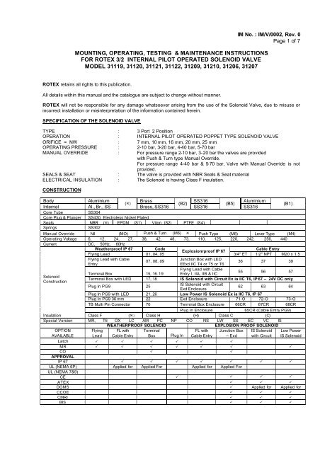
MOUNTING, OPERATING, TESTING & MAINTENANCE INSTRUCTIONS<br />
FOR ROTEX 3/2 INTERNAL PILOT OPERATED SOLENOID VALVE<br />
MODEL <strong>31119</strong>, 31120, 31121, 31122, 31209, 31210, 31206, 31207<br />
IM No. : IM/V/0002, Rev. 0<br />
Page 1 of 7<br />
ROTEX retains all rights to this publication.<br />
All details within this manual and the catalogue are subject to change without manner.<br />
ROTEX will not be responsible for any damage whatsoever arising from the use of the <strong>Solenoid</strong> <strong>Valve</strong>, due to misuse or<br />
incorrect installation or misinterpretation of the information contained herein.<br />
SPECIFICATION OF THE SOLENOID VALVE<br />
TYPE : 3 Port 2 Position<br />
OPERATION : INTERNAL PILOT OPERATED POPPET TYPE SOLENOID VALVE<br />
ORIFICE = NW : 7 mm, 10 mm, 16 mm, 20 mm, 25 mm<br />
OPERATING PRESSURE : 2-10 bar, 3-20 bar, 4-40 bar, 5-70 bar<br />
MANUAL OVERRIDE : For pressure range 2-10 bar, 3-20 bar the valves are provided<br />
with Push & Turn type Manual Override.<br />
For pressure range 4-40 bar & 5-70 bar, <strong>Valve</strong> with Manual Override is not<br />
provided.<br />
SEALS & SEAT : The valve is provided with NBR Seals & Seat material<br />
ELECTRICAL INSULATION : The <strong>Solenoid</strong> is having Class F insulation.<br />
CONSTRUCTION<br />
Body Aluminium Brass SS316 Aluminium<br />
(ø)<br />
(B2)<br />
(B5)<br />
Internal<br />
Al., Br., SS<br />
Brass, SS316 SS316<br />
SS316<br />
Core Tube<br />
SS304<br />
Core Plug & Plunger SS430, Electroless Nickel Plated<br />
Seals NBR (ø) EPDM (S1) Viton (S2) PTFE (S4)<br />
Springs<br />
SS302<br />
Manual Override Nil (MO) Push & Turn (M6) ø Push Type (M8) Lever Type (M4)<br />
Operating Voltage 6, 12, 24, 27, 38, 42, 48, 73, 110, 125, 220, 242, 256, 440<br />
Current DC, 50Hz, 60Hz<br />
Weatherproof IP 67 Code Cable Entry<br />
Explosionrproof IP 67<br />
Flying Lead 01, 04, 05<br />
3/4" ET 1/2" NPT M20 x 1.5<br />
Flying Lead with Cable<br />
07, 08, 09<br />
Junction Box with LED<br />
Entry<br />
EExd IIC T4 or T5 or T6<br />
36 37 39<br />
Flying Lead with Cable<br />
55 56 57<br />
Terminal Box 15, 16.19 Entry I, IIA, IIB & IIC<br />
<strong>Solenoid</strong><br />
Terminal Box with LED 17, 18 IS <strong>Solenoid</strong> with Circuit Ex ia IIC T6, IP 67 – 24V DC only<br />
Construction<br />
Plug In PG9 25<br />
IS <strong>Solenoid</strong> with Circuit<br />
62 63 64<br />
Exd Enclosure<br />
Plug In PG9 with LED 21, 26 Low Power IS <strong>Solenoid</strong> Ex ia IIC T6, IP 67<br />
Plug In PG9 36 mm 22 Exd Enclosure 71-O 72-O 73-O<br />
TB Multi Pin Connector 70 Terminal Box Enclosure 66CR 67CR 68CR<br />
Plug In Enclosure<br />
65CR (Cable Entry PG9)<br />
Insulation Class F (ø) Class H (H) Class C (C)<br />
Special Version MR, T6 OX LC AM PC NP CO NS LW SS EC VC IS<br />
WEATHERPROOF SOLENOID<br />
EXPLOSION PROOF SOLENOID<br />
OPTION<br />
AVAILABLE<br />
Flying<br />
Lead<br />
FL with<br />
Cable Entry<br />
Terminal<br />
Box Plug In<br />
FL with<br />
Cable Entry<br />
Junction Box<br />
– Exd<br />
IS <strong>Solenoid</strong><br />
with Circuit<br />
Low Power<br />
IS <strong>Solenoid</strong><br />
Latch P P P P P P<br />
MR P P P P P P P<br />
CO P P<br />
APPROVAL<br />
IP 67 P P P P P P P<br />
UL (NEMA 6P) Applied for Applied For Applied for Applied For<br />
UL (NEMA 7&9)<br />
CE P P P P<br />
ATEX P P P<br />
DGMS P Applied for Applied for<br />
CCOE P P P<br />
CMRI P P P<br />
BIS P P P<br />
(B1)
IM No. : IM/V/0002, Rev. 0<br />
Page 2 of 7<br />
IDENTIFICATION ON THE SOLENOID VALVE<br />
a) VALVE LABEL<br />
Label on the ROTEX <strong>Solenoid</strong> <strong>Valve</strong> shows the following details :<br />
(1)<br />
<br />
TYPE<br />
ROTEX AUTOMATION LIMITED<br />
VADODARA-390010, INDIA<br />
FLUID CONTROL SYSTEM<br />
<br />
<strong>31119</strong>-16-4G-B2-S2<br />
WO No. ATM MFG<br />
1E346/51 0-10 9/2005<br />
(3) (2) (4) (5)<br />
(1)<br />
ROTEX AUTOMATION LIMITED<br />
VADODARA-390010, INDIA<br />
FLUID CONTROL SYSTEM<br />
CODE : <strong>31119</strong>-16-4G-B2-S2<br />
ATM 0-10<br />
MEDIA AIR<br />
DATE 9/2005<br />
Sr. No. 1E346/51<br />
(1) Logo + Name & address of the Manufacturer<br />
(2) <strong>Valve</strong> Type / Code<br />
<strong>31119</strong> = <strong>Valve</strong> Model<br />
Suffix = Nil<br />
16 = Orifice ∅<br />
4G = Port Connection (BSP)<br />
B2 = Body Material (Brass)<br />
S2 = Seal Material (Viton)<br />
- = Manual Override (Push & Turn)<br />
110 V = <strong>Solenoid</strong> Voltage<br />
50 Hz = Current (AC)<br />
22<br />
<strong>Solenoid</strong> Construction<br />
= (Enclosure : Plug In)<br />
H<br />
= <strong>Solenoid</strong> Class ‘H’ Insulation<br />
Sp. Version = Nil<br />
(3) Work Order reference / Sr. No. of the <strong>Valve</strong><br />
(4) Operating Pressure<br />
(5) Month & Year of manufacture<br />
(6) <strong>Valve</strong> Symbol<br />
(7) Media<br />
(8) ATEX Ex mark for <strong>Valve</strong> (Non Electrical Part)<br />
(9) “CE” mark for ATEX and/or PED compliance.<br />
(6) (2) (4) (3) (5) (7)<br />
(1)<br />
ROTEX AUTOMATION LIMITED<br />
VADODARA-390010, INDIA<br />
I M2 T6 T.F.No. TF/V/001<br />
II 2GD T6<br />
TYPE<br />
<br />
WO No. ATM MFG<br />
(3) (2) (9) (8) (4) (5)<br />
b) SOLENOID LABEL<br />
(1)<br />
(1) Logo + Name of the Manufacturer<br />
ROTEX<br />
(2) <strong>Solenoid</strong> Type<br />
VADODARA – 390010, III = <strong>Solenoid</strong> Size III<br />
INDIA<br />
110V = <strong>Solenoid</strong> Voltage<br />
III-110V-50Hz-22-H 50 Hz = <strong>Solenoid</strong> Current<br />
04/2005-09/05 22 = <strong>Solenoid</strong> Construction (Plug In DIN)<br />
H = <strong>Solenoid</strong> Class H Insulation<br />
(3) Plan No. & Manufacturing Month / Year<br />
(2) (3)
IM No. : IM/V/0002, Rev. 0<br />
Page 3 of 7<br />
c) PORT IDENTIFICATION<br />
A solenoid <strong>Valve</strong> with NPT (F) threading is normally marked “N” near the port and with Metric threads are marked<br />
“M”. For ports with BSP threads, there is no marking.<br />
d) Voltage, current & other details are additionally marked/punched on the solenoid.<br />
NOTE : The product without label is out of warranty and risk.<br />
CONNECTION<br />
VALVE TYPE FUNCTION IN OUT EXHAUST PILOT VENT<br />
<strong>31119</strong>,31120,31121,31122 NC 1 2 3 6<br />
31209,31210,31206,31207 NO 3 2 1 6<br />
(A)<br />
OPERATING PRINCIPLE<br />
When the solenoid is de-energised and pressure applied at the inlet port, a part of media from the inlet is drawn through<br />
the pilot passage which is blocked under Plunger (Part-30). Port (2) and Port (3) are connected whereas Port (1) is<br />
blocked.<br />
On energisation of the solenoid, Plunger (Part-30) moves up thereby blocking pilot vent orifice. The air from pilot passage<br />
acts on the piston thus, pushing the poppet assembly down and thereby connecting to Port (1) to Port (2) and blocking Port<br />
(3). On de-energising the solenoid, the pilot air is vented through pilot vent. Thereby the spring and media air pushing the<br />
poppet assembly up.<br />
(B) MOUNTING/INSTALLATION PROCEDURE :<br />
1. ENSURE THAT :<br />
a) While storing, keep the valve in cool, dry, dust free area.<br />
b) On receipt of the valve, in case if the same is to be removed from the sealed plastic bag for<br />
inspection/testing, put them back with dust plugs on its ports and sealing the plastic bag as soon as the<br />
inspection/testing is over.<br />
c) The valve should be removed from its card board and/or plastic bag just before the installation.<br />
d) Flush lines before installing the valve.<br />
e) To avoid pressure drop and to achieve optimum parameters, Pipe / Tube / Fitting from the source of<br />
pressure to the valve and to the connected equipment should have ID which is ≥ NW (Orifice) of the<br />
valve.
IM No. : IM/V/0002, Rev. 0<br />
Page 4 of 7<br />
f) To avoid pressure drop, if more than one valve is being operated simultaneously from a common header,<br />
then minimum ID of the header can be calculated as under.<br />
ID Header = √ (NW 2 ×n)<br />
n = Number of <strong>Valve</strong>s operating at a time and which are connected to a common header,<br />
NW = Orifice of the <strong>Valve</strong>.<br />
g) Incorporate filter in the line to avoid hard particles entering into the valve.<br />
h) The valve should be installed for the media for which it is intended for. This is to avoid the malfunction of<br />
seals and the valve. In case if you intend to use valve for media other than the one specified on that<br />
valve, check compatibility of media to Body Seal material and grease. Consult ROTEX in case if any<br />
doubt.<br />
i) Do not try to drill any additional holes or machine, modify any of the valve components.<br />
j) In case if the valve is used for dangerous fluid gas/liquid then, the user is hereby advised to maintain<br />
during operation and maintenance of the valve below LEL or above UEL to avoid explosion due to<br />
internal spark as the valves have not been assessed for the same.<br />
k) Inlet pressure does not exceed rated pressure.<br />
l) Hemp-Filaments, ’Jute’ or even Teflon-Ribbons are normally not required, as the port connections of<br />
ROTEX <strong>Valve</strong> is accurately machined.<br />
m) To avoid over lap of the Teflon ribbon or cuts generated while tightening, getting carried away into the<br />
valve. Do not cover first two thread pitches with Teflon tape or sealant.<br />
n) For <strong>Solenoid</strong> <strong>Valve</strong> to be installed in European Union, check the applicability for ATEX, PED<br />
Directives. Refer separate Instruction Manual for ATEX approved <strong>Solenoid</strong> <strong>Valve</strong>.<br />
2. Provide Dust Cap on the exhaust port or ensure that the valve is mounted such a way that dust particles / rain<br />
water / process fluid do not enter into the valve through exhaust port of the valve. You can connect bend pipe of<br />
ID > NW of the valve so that the exhaust port is not directly (straight) open into the atmosphere.<br />
3. The process fluid etc. : do not fall on the valve body.<br />
4. In case if the surrounding atmosphere has traces or some other substance other than Air, check its compatibility<br />
with the Body material of the valve , <strong>Solenoid</strong> enclosure & other exposed parts.<br />
5. In case if the valve is installed in potentially Hazardous area, check for the temperature class of the <strong>Solenoid</strong> to<br />
avoid explosion due to heated <strong>Solenoid</strong> / other components.<br />
6. Provide fuse of proper rating to avoid excess current passing through the <strong>Solenoid</strong> and thereby avoiding<br />
over heating.<br />
7. It is not likely however, the user is advised to protect the valve against lightening as the same is not assessed.<br />
8. Check internal components (wetted) parts for its compatibility with fluid passing through the valve.<br />
9. It is recommended to replace all the Rubber Parts including Plunger Assembly (Repair Kit – Code 99) in<br />
case if the valve is to be installed and put in service after 2 years from the date of manufacture.<br />
10. APPLICABILITY OF PED<br />
For applicability of PED for the <strong>Solenoid</strong> <strong>Valve</strong> to be installed in European Union, refer chart given hereunder :<br />
Orifice<br />
in<br />
mm<br />
Non-Hazardous Gas<br />
Orifice > 32<br />
PS DN > 1000<br />
Hazardous Gas<br />
Orifice > 25<br />
PS DN > 1000<br />
Pressure Rating in Kg/cm2<br />
Non-Hazardous Liquid<br />
Orifice > 10<br />
PS DN > 5000<br />
Hazardous Liquid<br />
Orifice > 0.5<br />
PS DN > 2000<br />
25 mm - > 40 > 200 > 80<br />
40 mm > 25 > 25 > 125 > 50<br />
50 mm > 20 > 20 > 100 > 40<br />
65 mm > 15.38 > 15.38 > 76.92 > 30.76<br />
REMARKS<br />
1) <strong>Solenoid</strong> <strong>Valve</strong> in which media passing through the valve is Gaseous and Orifice less than 25mm, PED<br />
is not applicable.<br />
2) <strong>Solenoid</strong> <strong>Valve</strong> in which media passing through the valve is Liquid Hazardous nature, pressure 0.5 bar<br />
and Liquid Non-Hazardous nature, pressure below 10 bar, PEF is not applicable.<br />
ELECTRICAL<br />
1. Verify name plate affixed on the <strong>Solenoid</strong>.<br />
2. Connect the power supply according to the voltage rating of the <strong>Solenoid</strong><br />
3. Ensure that the cover of Junction Box/Terminal Box is properly tightened wherever applicable.<br />
4. Install valve in such a way that the rain water / other process fluid dripping along the cable does not fall on the<br />
SOV and has no possibility to run along the cable and enter into the Terminal area.<br />
5. Fill in the space between cable and gland entry with a proper sealant. If necessary, you may mount the valve<br />
upside down or in any other direction.<br />
6. Ensure that the <strong>Solenoid</strong> enclosure meets process and local authority requirement.
IM No. : IM/V/0002, Rev. 0<br />
Page 5 of 7<br />
7. The Plug In, Terminal Box, FPJB, IS <strong>Solenoid</strong>s are provided with test leads. Remove them before final<br />
installation.<br />
8. Check for proper connections for the <strong>Solenoid</strong> which are polarity sensitive e.g. (a) Latched <strong>Solenoid</strong> (b) EEx ia<br />
<strong>Solenoid</strong>.<br />
9. Refer separate manual for construction of the <strong>Solenoid</strong> and for specific instructions related to <strong>Solenoid</strong><br />
e.g. (a) EEx ia (b) Latched <strong>Solenoid</strong> (c) EExd <strong>Solenoid</strong> IP 67,IP 54<br />
10. Ensure that the solenoid construction is selected properly meeting the environment in which the valve is supposed<br />
to be installed e.g. use of Exd or Ex ia solenoid for valve to be installed in hazardous location or Weatherproof<br />
<strong>Solenoid</strong> having IP 67 for outdoor installation.<br />
11. Flying Lead <strong>Solenoid</strong> is not recommended to be used for outdoor or indoor application where water/liquid<br />
splashing or high humidity is present.<br />
MANUAL OVERRIDE OPERATION<br />
(A)<br />
(B)<br />
PUSH & TURN TYPE (M6)<br />
When the solenoid is deenergised (Photo-3) and inlet and outlet ports connected, applying rated pressure, the<br />
valve can be operated either pressing the Manual Override, when the same is released, the valve returns back to<br />
the normal position. The valve can also be locked in energized (Photo-4) position by pushing the Manual Override<br />
and rotating clockwise. To avoid Manual Override returning back to normal condition, ensure that the same is<br />
turned above 90º. The valve can be brought to normal condition by turning Manual Override anti clockwise.<br />
PUSH TYPE (M8) / LEVER TYPE (M4)<br />
When the solenoid is deenergised, inlet and outlet ports connection and rated pressure applied, the valve can be<br />
brought to energized position by pressing Manual Override / Lever. The valve remains in this position till Manual<br />
Override / Lever is pressed. As soon as the same is released, the valve returns back to the normal position.<br />
TESTING OF THE VALVE AT THE TEST BENCH<br />
Check at least once in 3 years or following your routine maintenance schedule.<br />
a) Apply rated pressure at inlet port of the valve.<br />
b) Plug outlet port.<br />
c) Check operation of the valve and leakage at the exhaust ports and pilot vent at the rated and minimum working<br />
pressure by applying 75% to 120% rated voltage.<br />
d) While keeping the solenoid de-energised, check operation and leakage from exhaust and pilot vent ports of the<br />
valve at the rated and minimum working pressure by operating Manual Override.<br />
e) Without connecting air supply to the valve, operate Manual Override. Energise and De-eneerigse <strong>Solenoid</strong> to<br />
check for the plunger movement (normally movement should not be there) which can be checked by click sound.<br />
After operating Manual Override if plunger movement is found, reduce length of the manual override by 0.3mm<br />
from its tapper end. Continue this till click sound stops.<br />
f) Check the insulation resistance of the <strong>Solenoid</strong> by applying 500V DC at terminals and the solenoid housing. It<br />
should be more than 100 Mega Ohms.<br />
RECOMMENDED SPARES<br />
a) Seal Kit (O Ring) (Code – 98).<br />
b) Plunger assembly (Part No. 30).<br />
c) Spare <strong>Solenoid</strong>. (Code – 34)<br />
d) Repair Kit (Code – 99)<br />
SPARE ORDERING CODE<br />
TYPE SUFFIX (a) (b) (c) (d) (e) SPARE CODE<br />
ORIFICE<br />
PORT CONNECTION<br />
BODY &<br />
INTERNAL<br />
MANUAL<br />
OVERRIDE<br />
SEAL<br />
Spare Part Description<br />
Plunger Assembly 30<br />
Seal Kit 98<br />
Repair Kit 99<br />
VALVE TYPE<br />
SPECIAL TOOLS<br />
• Guide Opening Tool : ROTEX Ref No. WN 1219 / M28 (Photo-1) or WN1219 / M22 (Photo-2) (ROTEX make).
IM No. : IM/V/0002, Rev. 0<br />
Page 6 of 7<br />
RECOMMENDED MAINTENANCE<br />
PREVENTIVE<br />
• Replacement of Complete Set of O Ring … … Once in 5 years or 2 million operations.<br />
- <strong>Solenoid</strong> O Ring (Part 35), Guide O Ring (Part 32),<br />
- MA O Ring (Part 22), Body O Ring (Part 20),<br />
- Seat O Ring (Part 19), Piston O Ring (Part 18)<br />
• Replacement of Plunger Assembly … … … Once in 5 years or 2 million operations<br />
• Replacement of the <strong>Solenoid</strong> … … … As and when required.<br />
• Check of Insulation Resistance, Resistance of the <strong>Solenoid</strong>… Once in a year (shouldbe > 100 MOhms @<br />
500V DC.<br />
• Check Resistance of the <strong>Solenoid</strong>… … … Replace <strong>Solenoid</strong> if the resistance reduces more<br />
(Not applicable for <strong>Solenoid</strong> with IS, RC options or<br />
than 5% computed at 20ºC as compared to its<br />
AC <strong>Solenoid</strong> with > 11 Watt power).<br />
Initial value.<br />
MAINTENANCE – GENERAL INSTRUCTION<br />
• The <strong>Solenoid</strong> <strong>Valve</strong> must be removed from the site and has to be maintained under safe conditions.<br />
— All air and electrical connections must be switched off before removing valve from the line.<br />
— It is recommended to replace complete set of O Ring even if one of the O Ring is damaged. This is to ensure<br />
trouble free operation of the valve and will avoid its premature failure.<br />
• Using Grease other than Silicon base Molykote M55 will lead to premature failure of O Rings of the ROTEX<br />
<strong>Solenoid</strong> valve.<br />
— If necessary to clean the components, do not use Kerosene, Diesel, Petrol to clean valve as this damages<br />
the O Rings and other rubber material. Instead use light Detergent Soap Solution.<br />
• Ensure that the components are free from dust, dirt, lint and metal burrs.<br />
• Twisting of O Ring should be avoided. Ensure that the twist is removed before fitting matching part.<br />
• While closing the matching part, the matching part should be pushed in a straight line. Turning motion should be<br />
avoided.<br />
• Pinching of O Ring at the groove corner at the time of closing gland should be avoided.<br />
• User is requested to use safe practice for maintenance.<br />
• It is important to place the dismantled <strong>Valve</strong> Parts on a clean paper or cloth in same sequence in which you have<br />
dismantled them.<br />
• Ensure to keep all the components of the valve separately to avoid their mixing up. The component appears tobe<br />
same may have small differences which will cause malfunction if interchanged.<br />
• In case of difficulty you should contact the Agent, Distributor or ROTEX directly.<br />
• Using ROTEX genuine spares will Guarantee you trouble free operation and will avoid premature failure.<br />
(A)<br />
TO REPLACE SOLENOID<br />
1) Open dome nut (Part 37) and pull out solenoid (Part 34)<br />
2) Replace new solenoid ensuring the construction, voltage and current meets the requirements.<br />
3) Tighten the dome nut (Part 37) applying torque of 0.2 kgm to 0.35 kgm to avoid over tightening of the<br />
solenoid.<br />
4) Measure and record resistance of the <strong>Solenoid</strong>.<br />
(B) TO REPLACE GUIDE ASSEMBLY (CORE TUBE) (Part 33) / PLUNGER (Part 30)<br />
1) Open dome nut (Part 37) and pull out solenoid (Part 34).<br />
2) Open Guide Assembly (Core Tube) (Part 33) using guide opening tool as per Photo - 2 or 3 (depending<br />
on the Guide Assembly (Core Tube) fitted on the valve).<br />
3) Remove Plunger Assembly (Part 30).<br />
4) Replace the necessary defective parts ensuring that the plunger assembly spring and the retaining ring is<br />
as per Photo - 5 or as per Photo – 6 & 7.<br />
5) The Plunger as per Photo - 6 & 7 is interchangeable and can be fitted in the existing Guide Assembly<br />
(Core Tube).<br />
6) Fix Guide Assembly (Core Tube) using correct tool.<br />
7) Fix the solenoid and dome nut as per Point-4 of procedure A.<br />
8) Eventhough it is not recommended, in case if required, the Guide Assembly (Core Tube) (Part 33) can<br />
be opened using plier or other similar tool ensuring that the same does not damage anything or<br />
component and the plier is tighten above weld joint (weld joint should be at the centre of plier jaw width).<br />
(C) REPLACEMENT OF MANUAL OVERRIDE (PART 8)<br />
1) Remove Grub Hex Socket Set Screw (Part 115) and pull out Manual Override (Part 8).<br />
2) Replace new Manual Override applying light layer of Silicon Grease Molykot M55 and tighten the grub<br />
screw fully till the Manual Override stops traveling in and out.<br />
3) Open the Grub Hex Socket Set Screw slightly (1/4 turn) and check the smooth movement of the grub<br />
screw.
IM No. : IM/V/0002, Rev. 0<br />
Page 7 of 7<br />
4) Without connecting air supply to the valve, operate Manual Override. Energise and De-eneerigse<br />
<strong>Solenoid</strong> to check for the plunger movement (normally movement should not be there) which can be<br />
checked by click sound.<br />
After operating Manual Override if plunger movement is found, reduce length of the manual override by<br />
0.3mm from its tapper end. Continue this till click sound stops.<br />
(D)<br />
REPLACEMENT OF O RINGS<br />
1) Remove solenoid if necessary as per Procedure (A).<br />
2) Remove Deckel (Cover) (Part 2) by opening four screws.<br />
3) Remove Ventilboden (<strong>Valve</strong> Bottom) (Part 3) using internal circlip plier.<br />
4) Remove Ventilfeder (<strong>Valve</strong> Spring) (Part 16).<br />
5) Open Nut (Part 12).<br />
6) Insert rod in hole provide in Ventilschaft (<strong>Valve</strong> Shaft) (Part 5) to remove Nut (Part 12).<br />
7) Remove all the O Rings [Piston O Ring (Part 18 – 1 No.), Seat O Ring (Part 19-2 Nos.), Body O Ring<br />
(Part 20 – 2 Nos.)].<br />
8) Clean components.<br />
9) Fix new O Rings applying light layer of Molykot M55 grease.<br />
10) Ensure that the O Rings and other rubber parts are compatible to the media passing through the valve.<br />
11) Reassemble the valve.<br />
12) Check operation and leakage of the valve.<br />
13) Contact ROTEX in case of any difficulty.<br />
STORING,CLEANING AND MOUNTING OF ELASTOMERS : SYNTHETIC RUBBER PRODUCTS<br />
• Store Plunger, O Ring Set in sealed polyethylene bag, kept in cool, dry, dust free area and avoid direct contact<br />
with all light sources emitting ultra violet rays, or contact with fumes, solvents, fuels, lubricants, chemicals, acids,<br />
disinfectants.<br />
• Follow Maintenance General Instruction & specific procedures to replace O Ring set as listed above.<br />
Guide Opening Tool M-28<br />
Photo – 1<br />
Guide Opening Tool M-22<br />
Photo - 2<br />
Manual Override “OFF”<br />
Photo – 3<br />
Manual Override “ON “<br />
Photo – 4<br />
Spring Dia Flat Face<br />
(Small) this side<br />
Photo – 5<br />
Plunger with fixed conical &<br />
cylindrical seal (Old Plunger)<br />
Photo – 6<br />
Plunger with moving seal<br />
(New Design Plunger)<br />
Photo – 7<br />
Contact :<br />
ROTEX AUTOMATION LIMITED<br />
987/11, GIDC, MAKARPURA, VADODARA – 390010, INDIA<br />
Tel. : +91 265 2638136, 2638746, 2638795 Fax : +91 265 2638130<br />
E-mail : rotexbrd@rotexindia.com Website : www.rotexindia.com