Perpendicularity Refinement - Technical Training Consultants
Perpendicularity Refinement - Technical Training Consultants
Perpendicularity Refinement - Technical Training Consultants

Create successful ePaper yourself
Turn your PDF publications into a flip-book with our unique Google optimized e-Paper software.
856 SALT LAKE COURT SAN JOSE, CA 95133 (408) 251–5329<br />
<strong>Perpendicularity</strong> <strong>Refinement</strong><br />
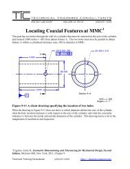
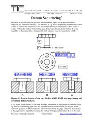
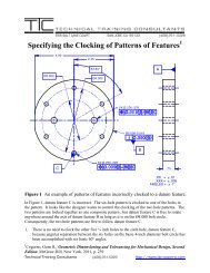
Recently a client asked me to look at a drawing that is similar to the one shown in Fig. 6-4A<br />
below. This part has three coaxial cylinders. The smallest cylinder must be coaxial to the 2.000<br />
diameter cylinder within a cylindrical tolerance of .010 in diameter, and both cylinders are to be<br />
perpendicular to datum feature A within a cylindrical tolerance of .005 in diameter.<br />
A<br />
Ø3.00<br />
Ø1.000<br />
Ø2.000<br />
B .XX = ± .01<br />
.XXX = ± .005<br />
Angles = ± 1°<br />
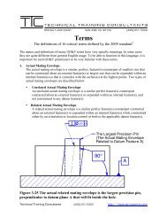
Figure 6-4A The inappropriate use of the position control to control<br />
perpendicularity<br />
In an attempt to control the perpendicularly of the 2.000 diameter cylinder in Fig. 6-4A, the<br />
designer incorrectly toleranced it with a position control. 1 If perpendicularity is required, use the<br />
perpendicularly control. In other words, say what you mean. Although the tolerance of position<br />
does control orientation when it is used to locate a feature, it is not used solely to control<br />
perpendicularity. In this case, perpendicularity is the only relationship that must be refined.<br />
Consequently, the perpendicularity tolerance is the correct control for this application as shown in<br />
Fig. 6-4B below.<br />
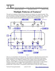
The composite tolerance shown in Fig. 6-4A is inappropriately applied to a single feature. This<br />
tolerance is only used to control patterns of features. A composite tolerance is used where the<br />
relationship from feature-to-feature in a pattern of features must be kept to a smaller tolerance than<br />
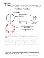
the relationship between the pattern and its datum features. Fig. 6-4B correctly shows the position<br />
control locating the axis of the 1.000 diameter cylinder within a cylindrical tolerance zone .010 in<br />
diameter, and a perpendicularity tolerance refining the orientation of the axis within a cylindrical<br />
tolerance zone of .005 in diameter. To refine the orientation of a single feature, specify the desired<br />
orientation tolerance, perpendicularity in this case, and place the orientation feature control frame<br />
beneath the location feature control frame.<br />
<strong>Technical</strong> <strong>Training</strong> <strong>Consultants</strong> (408) 251-5329 http://www.ttc-cogorno.com
NOTE:<br />
UNLESS OTHERWISE SPECIFIED,<br />
ALL COAXIAL FEATURES ARE<br />
COAXIAL WITHIN A CYLINDRICAL<br />
TOLERANCE ZONE Ø.020.<br />
A<br />
Ø3.00 Ø1.000<br />
Ø2.000<br />
Figure 6-4B The properly toleranced part shown in Fig. 6-4A<br />
B<br />
.XX = ± .01<br />
.XXX = ± .005<br />
Angles = ± 1°<br />
There is one final problem with the drawing in Fig. 6-4A. The two and three-inch diameter<br />
cylinders have no coaxiality control between them. As a result, the drawing is incomplete. It is a<br />
common misconception that the size tolerance in the tolerance block will control the coaxiality<br />
between two individual cylinders. The relationship between individual features is not controlled<br />
by the limits of size. If features on a drawing are shown coaxial, or symmetrical to each other, and<br />
not toleranced for location, the drawing is incomplete. Fig. 6-4B has a note specifying the<br />
tolerance between coaxial features. The use of a note is one-way of specifying the coaxiality<br />
tolerance for two or more individual features. Some designers feel that specifying coaxiality on<br />
prints is “overkill.” As a result of their mistaken beliefs, their companies have either already<br />
purchased bad parts or will purchase bad parts in the future. The proper tolerancing of parts avoids<br />
confusion, saves time, and saves money.<br />
1 Cogorno, Gene R., Geometric Dimensioning and Tolerancing for Mechanical Design, Second<br />
Edition, McGraw-Hill, New York, 2011, pp. 91 & 142.<br />
<strong>Technical</strong> <strong>Training</strong> <strong>Consultants</strong> (408) 251-5329 http://www.ttc-cogorno.com