Lab 2 Transformer Fundamentals - Department of Electrical and ...
Lab 2 Transformer Fundamentals - Department of Electrical and ...
Lab 2 Transformer Fundamentals - Department of Electrical and ...

You also want an ePaper? Increase the reach of your titles
YUMPU automatically turns print PDFs into web optimized ePapers that Google loves.
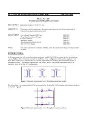
ELECTRICAL AND COMPUTER ENGINEERING<br />
THE CITADEL<br />
ELEC 302 <strong>Lab</strong> 2<br />
<strong>Transformer</strong> <strong>Fundamentals</strong><br />
REFERENCE: Appropriate chapters <strong>of</strong> ELEC 316 text.<br />
OBJECTIVE: The objective <strong>of</strong> this experiment is the experimental observation <strong>of</strong> the basic principals <strong>of</strong><br />
transformer operation.<br />
EQUIPMENT: Power Supply Module (0-120Vac) EMS 8821<br />
Resistance Module EMS 8311<br />
Inductance Module EMS 8321<br />
Capacitance Module EMS 8331<br />
<strong>Transformer</strong> Module EMS 8341<br />
Data Acquisition Interface (DAI) EMS 9062<br />
DAI 24V Power Supply EMS 30004<br />
Notes:<br />
This entire experiment is conducted at 60 Hz. All <strong>of</strong> the currents <strong>and</strong> voltages in this experiment<br />
are RMS<br />
INTRODUCTION:<br />
In this experiment, you will investigate the basic properties <strong>of</strong> a transformer. The transformer that you are studying<br />
should to a high degree, exhibit the properties <strong>of</strong> an ideal transformer.<br />
PRIOR PREPARATION:<br />
Complete the following at a time determined by the laboratory instructor.<br />
1. Review transformer fundamental found in your ELEC 316 text.<br />
PROCEDURE:<br />
WARNING!<br />
High voltages are present in this laboratory experiment!<br />
Do not make or modify any banana jack connections with the power on!<br />
Prior to energizing any circuit, ensure that the supply voltage has been adjusted to zero,<br />
slowly increase the supply voltage to the desired value while continuously monitoring the<br />
circuit currents. Note the transformer winding maximum current ratings. DO NOT<br />
EXCEED THESE RATINGS
PART ONE: Voltage Ratios<br />
1. Verify the all components required in the equipment section are present at the EMS workstation.<br />
2. Using the fluke multi-meter, measure <strong>and</strong> record the DC resistance <strong>of</strong> each transformer winding in Table 1.<br />
3. Make sure the main power switch <strong>of</strong> the Power Supply is OFF <strong>and</strong> the voltage control knob is fully CCW.<br />
Set the voltmeter selector switch to position 4-N.<br />
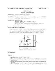
4. Construct the circuit <strong>of</strong> Figure 1. I1, I2, E1 <strong>and</strong> E2 refer to the DAI metering connections.<br />
5. Ensure the DAI 24V supply is connected to the main Power Supply (turn it on), <strong>and</strong> that the DAI USB<br />
connector is attached to the computer.<br />
6. Start the computer <strong>and</strong> the LVDAM EMS application. On the File menu open file C:\Program Files\<strong>Lab</strong><br />
Volt\Samples\E302_2.dai. The Metering window should display meters for E1, E2, E3, I1, <strong>and</strong> I2.<br />
7. Select focus to the metering window by clicking on it. Select Options -> Acquisition Settings, set the<br />
Sample Window dialog box to extended. Then click OK, <strong>and</strong> close the box. Select View -> check<br />
continuous refresh.<br />
8. Turn on the main voltage power supply <strong>and</strong> adjust the supply voltage to 120V. Monitor both the installed<br />
EMS voltmeter, <strong>and</strong> the metering window for proper indications. If proper indications are not immediately<br />
established, turn the voltage control knob CCW <strong>and</strong> turn <strong>of</strong>f the power supply. Obtain instructor assistance.<br />
9. Record in Table 2, the primary voltage E1 <strong>and</strong> the secondary voltage E2. Does the secondary voltage<br />
compare well with the rated value written on the transformer front panel?<br />
10. Turn the voltage control knob CCW, <strong>and</strong> turn <strong>of</strong>f the main power supply.<br />
Note: Before making any circuit changes that require installing or removing leads verify the power supply<br />
voltage is turned to zero <strong>and</strong> the power supply is OFF<br />
11. Rewire the circuit <strong>of</strong> Figure 1 to allow measurement <strong>of</strong> the remaining secondary voltages (E 3-4 , E 5-6 , E 7-8 ,<br />
ect.). Repeat steps 8 through 10 to complete Table 2.<br />
PART TWO: Current Ratio<br />
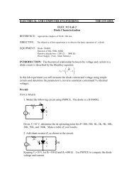
12. Construct the circuit <strong>of</strong> Figure 2. Note that I2 shorts the secondary windings 5-6. Turn on the power <strong>and</strong><br />
slowly adjust the voltage control to obtain a secondary current <strong>of</strong> 0.4 A. DO NOT EXCEED THE<br />
SECONDARY WINDING CURRENT RATING. Record the values <strong>of</strong> primary voltage, primary current<br />
<strong>and</strong> secondary current through windings 5-6. Turn the voltage control knob CCW, <strong>and</strong> turn <strong>of</strong>f the main<br />
power supply.<br />
E1 = _________ I1 = ___________<br />
I2 = __________<br />
13. Does the current ratio (I2/I1) correspond to the expected turns ratio ( N 1-2 /N 5-6 )?
PART THREE: Saturation<br />
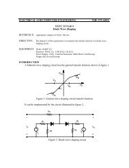
14. Construct the circuit <strong>of</strong> Figure 3, which will be used to display the effect <strong>of</strong> core saturation. Since the<br />
exciting current is small the voltage E1 across the resistor will be used to show its variation.<br />
15. Note that the supply voltage connection should now be from terminal 4 to 5. Set the voltmeter selector<br />
switch to position 4-5.<br />
16. Select the Data Table application. Click on options -> record settings <strong>and</strong> select E1, E2, <strong>and</strong> E3. They<br />
should now appear as columns in the data table.<br />
17. Increase the supply voltage in approximately 10V steps from 0-180V. At each step click the Record Data<br />
button to enter the measurements in the data table. When all data has been taken, turn the voltage control<br />
knob CCW, <strong>and</strong> turn <strong>of</strong>f the main power supply.<br />
Note that the above step requires applying a voltage that exceeds transformer rated voltage. This will not cause<br />
any damage to the transformer if applied for short periods <strong>of</strong> time. DO NOT LINGER AT VOLTAGES<br />
ABOVE 120V.<br />
18. Display the Graph application screen (use the menu bar on the data table), select E3 (representing the<br />
exciting current) as the x-axis, <strong>and</strong> E1 (applied voltage) as the y- axis. Click the Line Graph button to<br />
display the curve <strong>of</strong> primary voltage vs. exciting current.<br />
19. Does the curve illustrate that the transformer core has become saturated?<br />
20. Record the measured data into table 3 for the lab report.<br />
REPORT:<br />
Your report should be completed in the format requested by the instructor. Specifically, it must contain the<br />
following items.<br />
1. Completed Tables 1, 2, 3. Discussion <strong>of</strong> any questions posed in the lab procedure.<br />
2. Compare the nameplate values <strong>of</strong> secondary voltages to the experimental values in table 2. Compute <strong>and</strong><br />
tabulate the percent difference.<br />
Note: Percent Difference = [Experimental –Theoretical] x 100 / Theoretical.<br />
3. Make a plot <strong>of</strong> the saturation curve found in part three. Discuss the shape <strong>of</strong> this curve.
<strong>Transformer</strong><br />
EMS 8341<br />
4<br />
I1<br />
1<br />
3<br />
5<br />
I2<br />
Vs<br />
120Vac<br />
E1<br />
7<br />
8<br />
9<br />
E2<br />
N<br />
2<br />
4<br />
6<br />
Figure 1 Single Phase <strong>Transformer</strong> Circuit for part one.<br />
<strong>Transformer</strong><br />
EMS 8341<br />
4<br />
I1<br />
1<br />
3<br />
5<br />
Vs<br />
0-120 Vac<br />
E1<br />
7<br />
8<br />
9<br />
I2<br />
N<br />
2<br />
4<br />
6<br />
Figure 2 Single Phase <strong>Transformer</strong> Circuit for part two.<br />
R<br />
E3<br />
<strong>Transformer</strong><br />
EMS 8341<br />
4<br />
300<br />
1<br />
3<br />
5<br />
Vs<br />
0-208 Vac<br />
E1<br />
7<br />
8<br />
9<br />
E2<br />
5<br />
2<br />
4<br />
6<br />
Figure 3 Single Phase <strong>Transformer</strong> Circuit for part three.
Winding # Resistance<br />
Ω<br />
1-2<br />
3-4<br />
5-6<br />
7-8<br />
3-7<br />
8-4<br />
5-9<br />
9-6<br />
Table 1. Winding Resistances<br />
Winding #<br />
3-4<br />
5-6<br />
7-8<br />
3-7<br />
8-4<br />
5-9<br />
9-6<br />
Primary Voltage<br />
E1 Volts (1-2)<br />
Table 2. Primary <strong>and</strong> Secondary Voltages<br />
Secondary Voltage<br />
E2 Volts<br />
Turns ratio<br />
Np:Ns<br />
Primary Voltage<br />
E1 Volts (1-2)<br />
Secondary Voltage<br />
E2 Volts<br />
Exciting Voltage<br />
E3 Volts<br />
Table 3. Data for circuit <strong>of</strong> Fig. 3