product/part number index - MB Electronique
product/part number index - MB Electronique
product/part number index - MB Electronique

You also want an ePaper? Increase the reach of your titles
YUMPU automatically turns print PDFs into web optimized ePapers that Google loves.
MIL-STD-1553B CONCEPTS AND CONSIDERATIONS<br />
The digital data bus MIL-STD-1553B was designed in the early<br />
1970’s to replace analog point-to-point wire bundles between<br />
electronic instrumentation. The latest version of the serial local area<br />
network (LAN) for military avionics known as MIL-STD-1553B was<br />
issued in 1978. After 30 years of familiarity and reliable <strong>product</strong>s, the<br />
data bus continues to be the most popular militarized network.<br />
The MIL-STD-1553B bus has four main elements: (1) a bus<br />
controller that manages the information flow; (2) remote terminals<br />
that interface one or more simple subsystems to the data bus and<br />
respond to commands from the bus controller; (3) the bus monitor<br />
that is used for data bus testing; and (4) data bus components (bus couplers,<br />
cabling, terminators and connectors). Data is sequentially transmitted<br />
and received in a multiplexing scheme over two copper wires<br />
from computer to computer at a rate of 1 megabit per second. In<br />
most vehicle applications, redundant buses are employed.<br />
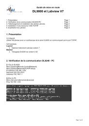
78 Ohm<br />
Terminator<br />
1-Stub Bus Coupler<br />
Stub Cable<br />
Assembly<br />
Bus Cable<br />
Assembly<br />
The data bus LAN topology encompasses:<br />
• bus couplers (coupling transformers with fault-isolation resistors)<br />
• terminators and cabling that includes twinax cable (twisted<br />
shielded pair)<br />
• concentric twinax connectors (with a center contact and an<br />
intermediate cylindrical contact)<br />
BUS<br />
CONTROL<br />
Bus couplers are available in various stub configurations including:<br />
• box type<br />
• in-line type (used in vehicles where light weight and small size<br />
are important)<br />
The purpose of the coupler is to reduce reflections and maintain<br />
signal impedance levels. Since direct coupled devices (without couplers)<br />
provide no DC isolation or common mode rejection, direct connection<br />
to the bus should be avoided. Without couplers, any shorting fault<br />
between the device's internal isolation resistors (usually found on the<br />
circuit board) and the main bus will cause failure of the entire bus<br />
because the device's internal isolation resistors are not sufficient to<br />
ensure against shorting out the bus. In addition to transformers, the bus<br />
couplers have built-in fault isolation resistors providing protection for<br />
the main bus in the event of a short circuit in the stub. All devices,<br />
including the bus controller, bus monitor and remote terminal, must be<br />
connected to the stub ends of the coupler .<br />
Both ends of the bus, whether it includes one coupler or a series<br />
of couplers connected together, must be terminated with 78 ohm<br />
terminators. Some couplers have built-in terminators and are generally<br />
used at the end of the bus in multi-coupler applications. These types<br />
of couplers are mainly for vehicle applications as they limit the flexibility<br />
of test lab set-ups. In a lab application, unused stub ports on the<br />
coupler need not be terminated since the stubs have a higher impedance<br />
than the bus. A high-impedance terminator (1000 to 3000 ohms) may<br />
be used in vehicle applications to simulate a future load from an<br />
unspecified device. In both cases, an RFI cap over the unused stub is<br />
a deterrent to interference and/or dust.<br />
MIL-STD-1553B does not specify the length of the bus. However, the<br />
maximum length of bus is directly related to the gauge of the cable<br />
conductor and time delay of the transmitted signal. A smaller conductor<br />
attenuates the signal more than a larger conductor. Typical propagation<br />
delay for a 1553B cable is 1.6 nanoseconds per foot. Thus, the end-to-end<br />
100-ft. bus would have a 160 nanosecond propagation delay, which is<br />
equal to the average rise time of a 1553B signal. According to<br />
MIL-HDBK-1553A, when a signal’s propagation delay time is more than<br />
50% of the rise or fall time, it is necessary to consider transmission line<br />
effects. This delay time is proportional to the distance propagated.<br />
Also, consideration must be given to the actual distance between the<br />
transmitter and receiver, and the individual waveform characteristics of<br />
the transmitters and receivers.<br />
TELEPHONE: 866.524.1553 www.milestek1553.com FAX: 940.591.7086