Pseudoheterodyne Detection in Nearfield Optics - Zurich Instruments
Pseudoheterodyne Detection in Nearfield Optics - Zurich Instruments
Pseudoheterodyne Detection in Nearfield Optics - Zurich Instruments

You also want an ePaper? Increase the reach of your titles
YUMPU automatically turns print PDFs into web optimized ePapers that Google loves.
is needed. By do<strong>in</strong>g this, it is important to dist<strong>in</strong>guish<br />
between field amplitude and field <strong>in</strong>tensity, which is the<br />
square of the field amplitude. All calculations can be performed<br />
<strong>in</strong> a post-process<strong>in</strong>g step follow<strong>in</strong>g data acquisition.<br />
Achievements<br />
In a collaboration with R. Brönnimann at the EMPA<br />
Dübendorf, Switzerland, the setup described is used to<br />
measure optical nearfields <strong>in</strong> the fW range. The NEP is<br />
estimated to 170 aW/√Hz, which is 2 orders of magnitude<br />
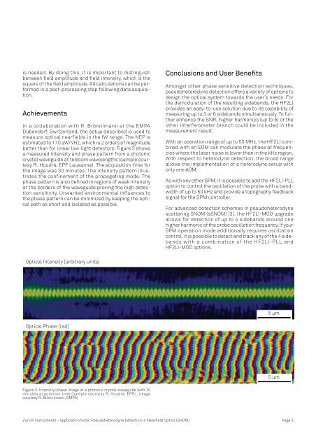
better than for l<strong>in</strong>ear low-light detectors. Figure 3 shows<br />
a measured <strong>in</strong>tensity and phase pattern from a photonic<br />
crystal waveguide at telecom wavelengths (sample courtesy<br />
R. Houdré, EPF Lausanne). The acquisition time for<br />
the image was 30 m<strong>in</strong>utes. The <strong>in</strong>tensity pattern illustrates<br />
the conf<strong>in</strong>ement of the propagat<strong>in</strong>g mode. The<br />
phase pattern is also def<strong>in</strong>ed <strong>in</strong> regions of weak <strong>in</strong>tensity<br />
at the borders of the waveguide prov<strong>in</strong>g the high detection<br />
sensitivity. Unwanted environmental <strong>in</strong>fluences to<br />
the phase pattern can be m<strong>in</strong>imized by keep<strong>in</strong>g the optical<br />
path as short and isolated as possible.<br />
Optical Intensity [arbitrary units]<br />
Optical Phase [rad]<br />
Figure 3. Intensity/phase image of a photonic crystal waveguide with 30<br />
m<strong>in</strong>utes acquisition time (sample courtesy R. Houdré, EPFL, image<br />
courtesy R. Brönnimann, EMPA)<br />
Conclusions and User Benefits<br />
Amongst other phase sensitive detection techniques,<br />
pseudoheterodyne detection offers a variety of options to<br />
design the optical system towards the user’s needs. For<br />
the demodulation of the result<strong>in</strong>g sidebands, the HF2LI<br />
provides an easy-to-use solution due to its capability of<br />
measur<strong>in</strong>g up to 3 or 6 sidebands simultaneously. To further<br />
enhance the SNR, higher harmonics (up to 6) or the<br />
other <strong>in</strong>terferometer branch could be <strong>in</strong>cluded <strong>in</strong> the<br />
measurement result.<br />
With an operation range of up to 50 MHz, the HF2LI comb<strong>in</strong>ed<br />
with an EOM can modulate the phase at frequencies<br />
where the laser noise is lower than <strong>in</strong> the kHz region.<br />
With respect to heterodyne detection, the broad range<br />
allows the implementation of a heterodyne setup with<br />
only one AOM.<br />
As with any other SPM, it is possible to add the HF2LI-PLL<br />
option to control the oscillation of the probe with a bandwidth<br />
of up to 50 kHz and provide a topography feedback<br />
signal for the SPM controller.<br />
For advanced detection schemes <strong>in</strong> pseudoheterodyne<br />
scatter<strong>in</strong>g SNOM (sSNOM) [3], the HF2LI-MOD upgrade<br />
allows for detection of up to 4 sidebands around one<br />
higher harmonic of the probe oscillation frequency. If your<br />
SPM operation mode additionally requires oscillation<br />
control, it is possible to detect and track any of the 4 sidebands<br />
with a comb<strong>in</strong>ation of the HF2LI-PLL and<br />
HF2LI-MOD options.<br />
<strong>Zurich</strong> <strong>Instruments</strong> - Application Note: <strong>Pseudoheterodyne</strong> <strong>Detection</strong> <strong>in</strong> <strong>Nearfield</strong> <strong>Optics</strong> (SNOM) Page 3<br />
5 μm<br />
5 μm