Building Roofs & Roof Styles - Home Design Software
Building Roofs & Roof Styles - Home Design Software
Building Roofs & Roof Styles - Home Design Software

You also want an ePaper? Increase the reach of your titles
YUMPU automatically turns print PDFs into web optimized ePapers that Google loves.
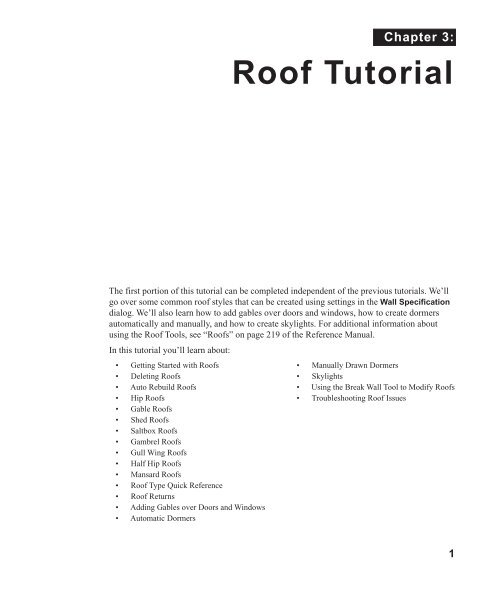
Chapter 3:<br />
<strong>Roof</strong> Tutorial<br />
The first portion of this tutorial can be completed independent of the previous tutorials. We’ll<br />
go over some common roof styles that can be created using settings in the Wall Specification<br />
dialog. We’ll also learn how to add gables over doors and windows, how to create dormers<br />
automatically and manually, and how to create skylights. For additional information about<br />
using the <strong>Roof</strong> Tools, see “<strong><strong>Roof</strong>s</strong>” on page 219 of the Reference Manual.<br />
In this tutorial you’ll learn about:<br />
• Getting Started with <strong><strong>Roof</strong>s</strong><br />
• Deleting <strong><strong>Roof</strong>s</strong><br />
• Auto Rebuild <strong><strong>Roof</strong>s</strong><br />
• Hip <strong><strong>Roof</strong>s</strong><br />
• Gable <strong><strong>Roof</strong>s</strong><br />
• Shed <strong><strong>Roof</strong>s</strong><br />
• Saltbox <strong><strong>Roof</strong>s</strong><br />
• Gambrel <strong><strong>Roof</strong>s</strong><br />
• Gull Wing <strong><strong>Roof</strong>s</strong><br />
• Half Hip <strong><strong>Roof</strong>s</strong><br />
• Mansard <strong><strong>Roof</strong>s</strong><br />
• <strong>Roof</strong> Type Quick Reference<br />
• <strong>Roof</strong> Returns<br />
• Adding Gables over Doors and Windows<br />
• Automatic Dormers<br />
• Manually Drawn Dormers<br />
• Skylights<br />
• Using the Break Wall Tool to Modify <strong><strong>Roof</strong>s</strong><br />
• Troubleshooting <strong>Roof</strong> Issues<br />
1
<strong>Home</strong> <strong>Design</strong>er Architectural 2014 User’s Guide<br />
Getting Started with <strong><strong>Roof</strong>s</strong><br />
To gain a basic understanding of roofs and how they function with <strong>Home</strong> <strong>Design</strong>er<br />
Architectural, we’ll begin this section of the tutorial with a new plan.<br />
To begin a new plan<br />
1. If any plans are open, select File> Close All from the menu.<br />
2. Select File> New Plan to open a new plan. In the Create New Plan dialog, select the<br />
Default Style template.<br />
3. Select Build> Wall> Straight Exterior Wall and draw a rectangular floor plan,<br />
measuring about 34 feet by 24 feet (approximately 10.4 m by 7.3 m), in a clockwise<br />
direction. We’ll use this outline to build a number of different roof styles. See “Drawing<br />
Walls” on page 115.<br />
Auto Rebuild <strong><strong>Roof</strong>s</strong><br />
Auto Rebuild <strong><strong>Roof</strong>s</strong> is a convenient feature in <strong>Home</strong> <strong>Design</strong>er Architectural that automatically<br />
rebuilds the roof in a plan whenever the exterior walls or floor/ceiling heights are changed.<br />
Auto Rebuild <strong><strong>Roof</strong>s</strong> is turned on by default, but this tutorial is presented with this feature<br />
disabled; however the information presented here also applies when it is enabled.<br />
2
Deleting <strong><strong>Roof</strong>s</strong><br />
To turn on/off Auto Rebuild <strong><strong>Roof</strong>s</strong><br />
1. Select Build> <strong>Roof</strong>> Build <strong>Roof</strong> from the menu.<br />
2. In the Build <strong>Roof</strong> dialog, check/uncheck Auto Rebuild <strong><strong>Roof</strong>s</strong> and click OK.<br />
Deleting <strong><strong>Roof</strong>s</strong><br />
<strong>Roof</strong> planes can be easily deleted in either of two ways.<br />
To delete a roof<br />
1. Select Build> <strong>Roof</strong>> Delete <strong>Roof</strong> .<br />
• Select Edit> Delete Objects and in the Delete Objects dialog, select All Rooms On<br />
This Floor; place a check beside <strong>Roof</strong>; and click OK.<br />
If a warning message states that roofs cannot be deleted while Auto Rebuild <strong>Roof</strong> is on, click<br />
the Yes button to turn off Auto Rebuild <strong>Roof</strong> and delete the roof.<br />
Hip <strong><strong>Roof</strong>s</strong><br />
When roofs are automatically generated, the default roof type is a hip roof, which means that a<br />
roof plane is built over every exterior wall in the plan that does not have another wall drawn<br />
above it.<br />
To create a hip roof<br />
1. Select Build> <strong>Roof</strong>> Build <strong>Roof</strong> from the menu to open the Build <strong>Roof</strong> dialog. The<br />
Pitch is set at 8 in 12 inches.<br />
2. Click OK to generate a hip roof.<br />
3
<strong>Home</strong> <strong>Design</strong>er Architectural 2014 User’s Guide<br />
3. Select 3D> Create >Full Overview to create a 3D overview of the house. If you wish,<br />
you can select 3D> Toggle Textures from the menu to turn off the display of textures.<br />
4. Select Window> Tile Vertically to see both views at the same time.<br />
Gable <strong><strong>Roof</strong>s</strong><br />
If you would like a gable over a particular wall rather than a roof plane bearing on it, you can<br />
specify it as a Full Gable Wall in the Wall Specification dialog.<br />
To create a gable over a wall, specify it as a Full Gable Wall. To create basic gable roof, two<br />
walls must be specified as such.<br />
To create a gable roof<br />
1. Click on the floor plan view window to make it the active view.<br />
2. Select Build> <strong>Roof</strong>> Delete <strong>Roof</strong> .<br />
3. Use the Select Objects tool to select one of the walls drawn vertically on screen.<br />
4. Click the Open Object edit button and on the <strong>Roof</strong> tab of the Wall Specification<br />
dialog, check Full Gable Wall and click OK.<br />
4
Gable <strong><strong>Roof</strong>s</strong><br />
• Alternatively, you can click the Change to Gable Wall(s) edit button.<br />
• To remove the Full Gable Wall attribute from a wall, you can select it and click the<br />
Change to Hip Wall(s) edit button.<br />
5. Modify the other vertically-drawn wall in the same manner.<br />
6. Select Build> <strong>Roof</strong>> Build <strong>Roof</strong> to open the Build <strong>Roof</strong> dialog and click OK.<br />
Attic Walls<br />
When a roof is generated, attic walls are also generated. An attic wall fills the space between<br />
the first floor walls and angled roof planes above. To see this in floor plan view, take a look at<br />
the second floor.<br />
If you do not want to see attic walls in floor plan view, you turn off their display.<br />
To turn off the display of attic walls<br />
1. In floor plan view, select Tools> Display Settings> Display Options (or press the ~<br />
key) to open the Display Options dialog.<br />
5
<strong>Home</strong> <strong>Design</strong>er Architectural 2014 User’s Guide<br />
2. Find Walls, Attic in the Name column, remove the check from the Disp column for this<br />
item, and click OK. For more information, see “Display Options Dialog” on page 65 of the<br />
Reference Manual.<br />
Shed <strong><strong>Roof</strong>s</strong><br />
To create a single, sloping roof plane, or shed roof, two walls must be specified as Full Gable<br />
Walls, and one must be a High Shed/Gable Wall.<br />
To create a shed roof<br />
1. Click on the floor plan view window to make it the active view.<br />
2. Select Build> <strong>Roof</strong>> Delete <strong>Roof</strong> .<br />
3. With the Select Objects tool, double-click the lower horizontal wall and on the <strong>Roof</strong><br />
tab of the Wall Specification dialog, check High Shed/Gable Wall and click OK.<br />
4. As in the Gable <strong>Roof</strong> example, specify the left and right vertical walls as Full Gable<br />
Walls.<br />
5. Select Build> <strong>Roof</strong>> Build <strong>Roof</strong> to open the Build <strong>Roof</strong> dialog and click OK.<br />
6
Saltbox <strong><strong>Roof</strong>s</strong><br />
Saltbox <strong><strong>Roof</strong>s</strong><br />
A saltbox is a type of gable roof with different pitches on each of the two roof planes and an<br />
offset ridge. Assign a different pitch to the two roof planes in the Wall Specification dialog for<br />
the wall supporting each one.<br />
To create a saltbox roof<br />
1. Click on the floor plan view window to make it the active view.<br />
2. Select Build> <strong>Roof</strong>> Delete <strong>Roof</strong> .<br />
3. With the Select Objects tool, double-click the lower horizontal wall. On the <strong>Roof</strong> tab<br />
of the Wall Specification dialog, remove the check from High Shed/Gable Wall and<br />
change the pitch to 12 in 12. Click OK to close the Wall Specification dialog.<br />
4. Leave the Full Gable Wall box checked for the two vertical walls.<br />
5. Select Build> <strong>Roof</strong>> Build <strong>Roof</strong> to open the Build <strong>Roof</strong> dialog, specify the pitch as 3<br />
in 12, and click OK.<br />
Gambrel <strong><strong>Roof</strong>s</strong><br />
A gambrel or barn style roof has two pitches on each side of the ridge. The first (lower) pitch<br />
on either side is steeper than the pitch near the ridge.<br />
7
<strong>Home</strong> <strong>Design</strong>er Architectural 2014 User’s Guide<br />
To create a gambrel roof<br />
1. Click on the floor plan view window to make it the active view.<br />
2. Select Build> <strong>Roof</strong>> Delete <strong>Roof</strong> .<br />
3. Select the horizontal walls and open them for specification. On the <strong>Roof</strong> tab:<br />
• Specify the lower Pitch as 12 in 12.<br />
• Place a check in the box beside Upper Pitch.<br />
• Keep the Upper Pitch as 6 in 12 and change the Start Height to 156.<br />
4. Click OK to close the Wall Specification dialog.<br />
5. The two vertical walls should remain Full Gable Walls.<br />
6. Open the Build <strong>Roof</strong> dialog, specify the Pitch as 6 in 12 once again, and click OK.<br />
Experiment with alternate pitches and overhangs. Also, try varying the height at which the<br />
second pitch begins so that you can see the effect it has on your gambrel roof design.<br />
8
Gull Wing <strong><strong>Roof</strong>s</strong><br />
Gull Wing <strong><strong>Roof</strong>s</strong><br />
A gull wing roof has two pitches on either side of the ridge, as a gambrel does; but the first<br />
pitch of a gull wing is shallower than the second.<br />
To create a gull wing roof<br />
1. Click on the floor plan view window to make it the active view.<br />
2. Select Build> <strong>Roof</strong>> Delete <strong>Roof</strong> .<br />
3. Change the following settings for each of the horizontal walls on the <strong>Roof</strong> tab of the Wall<br />
Specification dialog:<br />
• Specify the lower Pitch as 3 in 12.<br />
• Place a check in the box beside Upper Pitch.<br />
• Keep the Upper Pitch as 12 in 12 and change the Start Height to 125".<br />
4. The two vertical walls remain Full Gable Walls.<br />
5. Click the Build <strong>Roof</strong> tool and click OK in the Build <strong>Roof</strong> dialog.<br />
9
<strong>Home</strong> <strong>Design</strong>er Architectural 2014 User’s Guide<br />
Experiment with the height at which the second pitch begins so that you can see the effect it has<br />
on your gull wing roof design.<br />
Half Hip <strong><strong>Roof</strong>s</strong><br />
A half hip roof has two gable ends. At the top of each gable is a small hip that extends to the<br />
ridge.<br />
To create a half hip roof<br />
1. Click on the floor plan view window to make it the active view.<br />
2. Select Build> <strong>Roof</strong>> Delete <strong>Roof</strong> .<br />
3. With the Select Objects tool, double-click each wall and make these changes on the<br />
<strong>Roof</strong> tab of the Wall Specification dialog:<br />
For the two Horizontal walls:<br />
• Specify the lower Pitch as 6 in 12.<br />
• Uncheck the box beside Upper Pitch.<br />
For the two Vertical walls:<br />
10
Mansard <strong><strong>Roof</strong>s</strong><br />
• Leave the Full Gable Wall box checked.<br />
• Check the box beside Upper Pitch.<br />
• Specify the Upper Pitch as 3 in 12 and set the Start Height at 170".<br />
4. Click the Build <strong>Roof</strong> tool and click OK in the Build <strong>Roof</strong> dialog.<br />
Mansard <strong><strong>Roof</strong>s</strong><br />
A mansard roof is a hip roof with two slopes on the roof sections above each of the four walls.<br />
The second slope begins at the same height above each wall. The upper slope is usually quite<br />
gentle and the lower slope, much steeper.<br />
To create a mansard roof<br />
1. Click on the floor plan view window to make it the active view.<br />
2. Select Build> <strong>Roof</strong>> Delete <strong>Roof</strong> .<br />
3. Select all four walls, open them for specification, and on the <strong>Roof</strong> tab of the Wall<br />
Specification dialog specify the following settings:<br />
11
<strong>Home</strong> <strong>Design</strong>er Architectural 2014 User’s Guide<br />
• Clear the Full Gable Wall checkbox.<br />
• Specify the lower Pitch as 24 in 12.<br />
• Place a check in the box beside Upper Pitch.<br />
• Keep the Upper Pitch as 1.5 in 12 and change the Start Height to 132".<br />
4. Click the Build <strong>Roof</strong> tool and click OK in the Build <strong>Roof</strong> dialog.<br />
12
<strong>Roof</strong> Type Quick Reference<br />
<strong>Roof</strong> Type Quick Reference<br />
The following chart provides a quick reference for building the roof styles described in this<br />
tutorial. The chart shows which walls to change and what to change on the <strong>Roof</strong> tab of the Wall<br />
Specification dialog for each wall. These parameters are based on a 34x24-foot model. For<br />
different size plans, adjust these numbers.<br />
<strong>Roof</strong><br />
Type<br />
Gable<br />
<strong>Roof</strong><br />
Shed<br />
<strong>Roof</strong><br />
Saltbox<br />
<strong>Roof</strong><br />
Gambrel<br />
<strong>Roof</strong><br />
Gull Wing<br />
<strong>Roof</strong><br />
Half<br />
<strong>Roof</strong><br />
Hip<br />
Mansard<br />
<strong>Roof</strong><br />
Wall to Change<br />
Set as<br />
Full<br />
Gable<br />
Set as<br />
High<br />
Shed<br />
Gable<br />
Lower<br />
Pitch<br />
Upper<br />
Pitch<br />
Start<br />
Height<br />
Vertical Wall 1<br />
Vertical Wall 2<br />
Horizontal Wall 1 X<br />
Horizontal Wall 2 X<br />
Vertical Wall 1 X<br />
Vertical Wall 2 X<br />
Horizontal Wall 1<br />
X<br />
Horizontal Wall 2<br />
Vertical Wall 1 X<br />
Vertical Wall 2 X<br />
Horizontal Wall 1 12 in 12<br />
Horizontal Wall 2 3 in 12<br />
Vertical Wall 1 X<br />
Vertical Wall 2 X<br />
Horizontal Wall 1 12 in 12 6 in 12 156<br />
Horizontal Wall 2 12 in 12 6 in 12 156<br />
Vertical Wall 1 X<br />
Vertical Wall 2 X<br />
Horizontal Wall 1 3 in 12 12 in 12 125<br />
Horizontal Wall 2 3 in 12 12 in 12 125<br />
Vertical Wall 1 X 3 in 12 170<br />
Vertical Wall 2 X 3 in 12 170<br />
Horizontal Wall 1 6 in 12<br />
Horizontal Wall 2 6 in 12<br />
Vertical Wall 1 12 in 12 1.5 in 12 132<br />
Vertical Wall 2 12 in 12 1.5 in 12 132<br />
Horizontal Wall 1 12 in 12 1.5 in 12 132<br />
Horizontal Wall 2 12 in 12 1.5 in 12 132<br />
13
<strong>Home</strong> <strong>Design</strong>er Architectural 2014 User’s Guide<br />
<strong>Roof</strong> Returns<br />
A roof return is a small decorative roof plane that connects to the low side of a gable roof<br />
overhang and extends below the upper triangular portion of the gable wall. While you can build<br />
these manually, the following pictures illustrate the three styles of roof returns that can be<br />
produced automatically in <strong>Home</strong> <strong>Design</strong>er Architectural.<br />
Gable Return Hip Return Full Return<br />
The first two are called Gable and Hip returns, since the returns themselves end in either a<br />
gable or a hip. The third is called a Full return because it extends under the entire gable,<br />
connecting both sides. Full roof returns are sometimes referred to as water tables.<br />
The <strong>Roof</strong> tab of the Wall Specification dialog contains the settings that generate roof returns.<br />
<strong>Roof</strong> returns can be specified for any wall, but only exterior Full Gable Walls can display<br />
them.<br />
Specify the horizontal Length of the returns in inches; the distance to Extend the returns past<br />
the main roof overhang; the style of roof return; and whether the returns are sloping or flat. As<br />
long as your model has a roof, the specified roof returns will be generated when you click OK.<br />
For more information, see “<strong>Roof</strong> Returns” on page 232 of the Reference Manual.<br />
14
Adding Gables over Doors and Windows<br />
Adding Gables over Doors and Windows<br />
You can add a gable roof over a door or window.<br />
To create a gable roof over a door or window<br />
1. Select a door or window, then click the Gable Over Door/Window edit button.<br />
2. Click the Build <strong>Roof</strong> tool and click OK in the Build <strong>Roof</strong> dialog.<br />
3. A gable is created with an overhang of one foot on each side of the door or window.<br />
To remove a gable roof over a door or window<br />
1. Select the door or window and click the Delete Gable Over Opening edit button.<br />
2. Click the Build <strong>Roof</strong> tool and click OK in the Build <strong>Roof</strong> dialog.<br />
3. When you rebuild the roof, the gable will be removed.<br />
To create a gable over several doors and/or windows<br />
1. Select a door, window, or mulled unit.<br />
1. Hold down the Shift key and click on additional doors and/or windows to add them to your<br />
selection set.<br />
2. Click the Gable Over Door/Window edit button.<br />
3. Click the Build <strong>Roof</strong> tool and click OK in the Build <strong>Roof</strong> dialog to create a gable over<br />
the selected wall openings.<br />
15
<strong>Home</strong> <strong>Design</strong>er Architectural 2014 User’s Guide<br />
Automatic Dormers<br />
The Dormer tool offers a quick and convenient alternative to drawing dormers manually.<br />
With just a few clicks an entire dormer is placed, complete with roof, roof hole, walls, and<br />
window.<br />
There is a limit to how low the roof pitch can be set when creating dormers. Generally, 9 in 12<br />
is the lowest pitch that will provide enough elevation to contain a dormer.<br />
A Dormer<br />
contain it.<br />
can be placed anywhere within a roof plane, as long as there is enough space to<br />
Select Build> <strong>Roof</strong>> Build <strong>Roof</strong>> Dormer and click within an existing roof plane to place<br />
a floating dormer at that location. Once a dormer is created, it can be moved, resized and<br />
opened for specification. For more information, see “Editing Auto Dormers” on page 230 of<br />
the Reference Manual.<br />
A Dormer cannot initially be placed so that its walls align with an<br />
exterior wall. Once it is created, its front wall can often be aligned<br />
with an exterior wall below; however, its side walls must remain inside the<br />
exterior walls.<br />
Manually Drawn Dormers<br />
To create dormers in an upper floor, create a new floor for your plan and modify this floor with<br />
knee walls and windows to form gables. We’ll start with a new 40 x 30 foot plan to learn this<br />
technique.<br />
As with automatic dormers, roof pitches of 9 in 12 or greater generally work better than<br />
shallow pitches when creating dormers because they provide enough vertical space to build the<br />
dormer within.<br />
To create a new plan<br />
1. Select File> Close All from the menu to close any open plans.<br />
2. Select File> New Plan to open a new plan. In the Create New Plan dialog, select the<br />
Default Style template.<br />
3. Select Build> Wall> Straight Exterior Wall and draw a rectangular floor plan, 40<br />
feet by 30 feet, in a clockwise direction.<br />
4. Click the Fill Window <strong>Building</strong> Only button to zoom in on the house.<br />
16
Manually Drawn Dormers<br />
5. Select File> Save from the menu, save the file to an easy to find location, such as<br />
Documents, and give the plan a name.<br />
6. Select the right and left vertical walls, open them for specification, and on the <strong>Roof</strong> tab of<br />
the Wall Specification dialog, click the Full Gable Wall check box and click OK.<br />
7. Select Build> Floor> Build New Floor .<br />
8. Check the Derive new 2nd floor plan from 1st floor plan option in the New Floor dialog<br />
and click OK to display the Floor 2 Defaults dialog. Leave these settings at their default for<br />
now and click OK.<br />
9. Select Build> <strong>Roof</strong>> Build <strong>Roof</strong> , change the pitch to 12 in 12, and click OK in the<br />
Build <strong>Roof</strong> dialog.<br />
17
<strong>Home</strong> <strong>Design</strong>er Architectural 2014 User’s Guide<br />
To create two knee walls<br />
A knee wall is a short wall on an upper floor that is cut off by a roof plane.<br />
1. Select Build> Wall> Straight Interior Wall and draw a horizontal interior wall (from<br />
left to right). Position this knee wall so that it is 5 feet from the top exterior wall.<br />
You can also create a custom wall type for the knee walls, such as a<br />
wall with only a framing layer and one sheetrock layer. See “Wall<br />
Type Definitions Dialog” on page 129 of the Reference Manual.<br />
2. Draw another interior wall (from right to left) and position it 5 feet from the bottom<br />
exterior wall. You can reposition the knee walls using dimensions. For more information,<br />
see “Moving Objects Using Dimensions” on page 438 of the Reference Manual.<br />
18
Manually Drawn Dormers<br />
3. Select each of the interior walls one at a time and click the Open Object edit button.<br />
Check Knee Wall on the <strong>Roof</strong> tab of the Wall Specification dialog and click OK.<br />
4. Select CAD> Dimensions> Automatic Exterior Dimensions to create exterior<br />
dimension lines for your plan, which should now look like this:<br />
To build the dormer walls<br />
1. Select Build> Wall> Straight Exterior Wall and draw two rectangular boxes on the<br />
outside of the lower interior wall, as shown in the following image.<br />
2. Position the lower walls of each dormer box 2 feet from the bottom wall. The lower<br />
dormer walls are those parallel to the bottom wall.<br />
3. Edit each dormer box so that it is 6 feet from each vertical side wall and 8 feet wide.<br />
19
<strong>Home</strong> <strong>Design</strong>er Architectural 2014 User’s Guide<br />
4. Select Build> Wall> Break Wall and click along the lower interior wall to place wall<br />
breaks as indicated in center of each overall in the following image.<br />
5. Delete the upper, horizontal portion of each window box.<br />
To add a window to each dormer<br />
1. Select Build> Window> Window and click on each dormer front wall to place a<br />
window. The program may warn you that you are adding windows to an interior wall; click<br />
OK to continue.<br />
2. Select the window; click the Center Object edit button; and click near the wall<br />
containing the window to center it on the wall. See “Using Center Object” on page 99 of<br />
the Reference Manual.<br />
3. Do the same for the other window.<br />
To build the roof<br />
1. Select the two dormer front walls that contain a window, open them for specification, and<br />
on the <strong>Roof</strong> tab of the Wall Specification dialog, check Full Gable Wall and click OK.<br />
20
Manually Drawn Dormers<br />
2. Select the dormer side walls, open them for specification, and on the <strong>Roof</strong> tab of the Wall<br />
Specification dialog, specify the Pitch for the dormer roof plane above the wall, and click<br />
OK. Earlier we specified a pitch of 12 in 12 in the Build <strong>Roof</strong> dialog, that pitch should<br />
have prefilled here. A steep pitch of 12 in 12 will work well for these dormers.<br />
3. Double-click the narrow room above the top knee wall to open the Room Specification<br />
dialog, designate its Room Type as “Attic” and click OK.<br />
4. Do the same for the lower attic room.<br />
5. Select Build> <strong>Roof</strong>> Build <strong>Roof</strong> from the menu.<br />
6. In the Build <strong>Roof</strong> dialog and click OK.<br />
7. Create a 3D view to see the results.<br />
21
<strong>Home</strong> <strong>Design</strong>er Architectural 2014 User’s Guide<br />
8. Notice there are small gaps in the dormer side walls. This gap is caused by the difference<br />
between the position of the knee walls and the point at which the ceiling intersects the roof<br />
plane. This location is marked by the black dotted line in floor plan view.<br />
9. Select each of the knee walls and move them back so that they are in alignment with the<br />
ceiling plane. The walls will snap into position when they are close to the ceiling lines.<br />
10. Take a look in a 3D view.<br />
22
Skylights<br />
You can move the interior walls closer to or further from the outside walls to change the<br />
dormers’ elevation, or change the pitch for the roof to make the dormers longer. You can create<br />
dormers in more complex plans the same way, but you may want to experiment with wall<br />
placement and pitch to achieve the desired effect.<br />
Skylights<br />
Skylights can easily be added using the Skylight tool. In floor plan view, select Build><br />
<strong>Roof</strong>> Skylight then click and drag a rectangular shape within an existing roof plane.<br />
When you release the mouse button, a skylight is created and can be repositioned and resized<br />
using its edit handles. For more information, see “Skylights” on page 227 of the Reference<br />
Manual.<br />
23
<strong>Home</strong> <strong>Design</strong>er Architectural 2014 User’s Guide<br />
Using the Break Wall Tool to Modify <strong><strong>Roof</strong>s</strong><br />
Many homes have more than one roof type built above a single exterior wall. One common<br />
example is a reverse gable roof, created when a house has gable walls that are perpendicular to<br />
one another, as in an L-shaped home.<br />
We can create a reverse gable roof on an L-shaped home using the Break Wall<br />
tool.<br />
To create an L-shaped home<br />
1. Select File> Close All from the menu.<br />
2. Select File> New Plan to open a new plan. In the Create New Plan dialog, select the<br />
Default Style template.<br />
3. Draw an L-shaped house with the following dimensions:<br />
• Left wall - 30 feet long<br />
• Upper wall - 45 feet long.<br />
• Right wall 18 feet long.<br />
• Lower wall extending left from the right wall - 25 feet long.<br />
• Vertical wall connecting two lower walls - 12 feet long.<br />
• Lower wall extending right from the left wall - 20 feet long.<br />
4. If desired, turn off Auto Rebuild <strong>Roof</strong> and delete the roof.<br />
24
Using the Break Wall Tool to Modify <strong><strong>Roof</strong>s</strong><br />
To create a reverse gable in this plan, we need to create three gable walls: two running<br />
vertically and one horizontally.<br />
To add a gable roof to the plan<br />
1. Check Full Gable Wall on the <strong>Roof</strong> tab of the Wall Specification dialog for these three<br />
walls:<br />
• The far left vertical wall<br />
• The far right vertical wall<br />
• The bottom left horizontal wall<br />
2. Click the Build <strong>Roof</strong> tool to open the Build <strong>Roof</strong> dialog and click OK to build the<br />
roof. Your plan should look like this:<br />
Built this way, the gable wall on the left produces roof planes that extend too high and will<br />
interfere with the roof over the lower part of the house. To correct this, use the Break Wall<br />
25
<strong>Home</strong> <strong>Design</strong>er Architectural 2014 User’s Guide<br />
tool to break the left wall into two different sections. We can then specify the upper section as<br />
Full Gable without affecting the lower section.<br />
To use the Break Wall tool<br />
1. Select Build> Wall> Break Wall and click the far left wall at a point even with the<br />
lower right wall.<br />
• An easy way to do this is to temporarily stretch the lower right wall across to the left<br />
wall;<br />
• Place a wall break where the walls meet;<br />
• Then return the lower right wall to its correct position.<br />
2. Open the lower portion of the wall for specification and on the <strong>Roof</strong> tab of the Wall<br />
Specification dialog, clear the Full Gable Wall checkbox and click OK.<br />
3. Click the Build <strong>Roof</strong> tool and click OK to build a roof based on the new wall<br />
specifications.<br />
You now have two full gable roof sections meeting to form your L-shaped roof. Your plan<br />
should look like the following image:<br />
26
Adding a <strong>Roof</strong><br />
Notice the step in the ridge line. This can be corrected by resizing the lower gable wall. Select<br />
the vertical wall to the right of the bottom gable wall and move it to the left 2 feet, reducing the<br />
length of the gable wall from 20 to 18 feet. When you are finished, rebuild the roof.<br />
This completes this <strong>Roof</strong> Tutorial. You can use any combination of the techniques described<br />
here to create a wide variety of roof planes. Let’s return to our Stucco Beach House plan and<br />
apply what we have learned.<br />
Adding a <strong>Roof</strong><br />
Now that we have a basic understanding of the automatically roof tools, let’s return to our<br />
previously saved Stucco Beach House plan, as it looks like our house could use a roof now.<br />
Let’s select File> Save As and give this plan a new name, such as "Beach House <strong>Roof</strong><br />
Tutorial" before continuing.<br />
27
<strong>Home</strong> <strong>Design</strong>er Architectural 2014 User’s Guide<br />
To edit the default roof<br />
1. Close any other views you may still have open. For the following steps, only the floor plan<br />
view should be open.<br />
2. Starting on Floor 1, we will start by using the Select Objects tool to select the top<br />
horizontal exterior Kitchen wall, as indicated in the image below.<br />
3. Click on the Open Object edit button to display the Wall Specification dialog, go to<br />
the <strong>Roof</strong> tab, place a checkmark in the Full Gable Wall option, and click OK.<br />
4. Click Up One Floor to go to the second floor.<br />
5. Using the Select Objects tool, select the Balcony room, then click on the he Open<br />
Object edit button to open the Room Specification dialog, and on the Structure tab,<br />
uncheck <strong>Roof</strong> Over this Room if it is selected, then click OK.<br />
6. Open the following second floor walls’ specification dialogs and assign the settings shown<br />
in the following image on the <strong>Roof</strong> tab of the Wall Specification dialog. See “<strong>Roof</strong> Tab”<br />
on page 132 of the Reference Manual.<br />
28
Adding a <strong>Roof</strong><br />
Individual walls can be selected and edited in both 2D and 3D views. See “Editing Walls”<br />
on page 120 of the Reference Manual.<br />
Full Gable Wall<br />
Full Gable<br />
Wall<br />
Extend<br />
Slope<br />
Downward<br />
Full<br />
Gable<br />
Wall<br />
Full Gable<br />
Wall<br />
Full Gable<br />
Wall<br />
Extend<br />
Slope<br />
Downward<br />
Full Gable Wall<br />
7. Once we have completed defining these walls on Floor 2, we are ready to create our roof.<br />
To turn on automatic roof generation<br />
1. Select Build> <strong>Roof</strong>> Build <strong>Roof</strong> from the menu to open the Build <strong>Roof</strong> dialog.<br />
2. On the <strong>Roof</strong> tab, check Auto Rebuild <strong><strong>Roof</strong>s</strong>. See “Build <strong>Roof</strong> Dialog” on page 222 of the<br />
Reference Manual for more information.<br />
3. Set the Pitch (in 12) to 3".<br />
29
<strong>Home</strong> <strong>Design</strong>er Architectural 2014 User’s Guide<br />
4. You can go to the Materials tab to change the material of your roof, where we will choose<br />
an Earth <strong>Roof</strong> Tile material.<br />
5. Click OK to close the dialog and generate a roof.<br />
6. Recall that the additional walls you now see displayed are attic walls.<br />
7. Select 3D> Create View> Full Overview to create a exterior view of your plan.<br />
Troubleshooting <strong>Roof</strong> Issues<br />
Creating a roof can require experimentation and practice. Here are some suggestions for<br />
troubleshooting a problematic roof design.<br />
<strong>Roof</strong> Directives in Walls<br />
As discussed in this chapter and in the <strong><strong>Roof</strong>s</strong> chapter of the <strong>Home</strong> <strong>Design</strong>er Architectural 2014<br />
Reference Manual, the program will automatically generate a roof plane bearing over each<br />
30
Troubleshooting <strong>Roof</strong> Issues<br />
exterior wall in a plan to produce a hip roof. If you require a different condition over a<br />
particular wall, such as a triangular gable or side wall of a shed roof, you can specify that<br />
condition on the <strong>Roof</strong> tab of the Wall Specification dialog. See “<strong>Roof</strong> Tab” on page 132 of the<br />
Reference Manual.<br />
Specifying roof directives that do not reflect what you require directly above a selected wall,<br />
however, can often result in drastic and unwanted changes to your roof. For example, when two<br />
parallel walls are specified as Full Gable Walls, a single ridge will be created between them.<br />
If a wall that is perpendicular to these walls is also specified as a Full Gable Wall, the roof<br />
becomes more complex with an additional ridge, two valleys, and two hips.<br />
If you are seeing hips or valleys in your roof where you do not expect them, revisit the <strong>Roof</strong> tab<br />
of the walls supporting the affected roof planes.<br />
<strong>Roof</strong> Heights<br />
The heights of all roof planes are based on the heights of the walls that they bear on. Wall<br />
heights, in turn, are determined by the ceiling heights of the rooms that they define. See “Floor<br />
& Ceiling Heights” on page 149 of the Reference Manual.<br />
31
<strong>Home</strong> <strong>Design</strong>er Architectural 2014 User’s Guide<br />
For example, the hip roof over a simple rectangular structure with a consistent ceiling heights<br />
(in this case, 109 1/8") has four roof planes.<br />
This roof will become considerably more complex if one room inside is given a lowered ceiling<br />
height (in this case, 97 1/8").<br />
32
Troubleshooting <strong>Roof</strong> Issues<br />
If you generate a roof and it seems to be more complicated and has more roof planes than it<br />
should, take a look at the ceiling heights of the rooms in the plan. Often, the correct way to<br />
create a lowered ceiling condition will be to set the ceiling at the default height create a<br />
lowered Ceiling Finish. See “Lowered Ceilings” on page 150 of the Reference Manual.<br />
Controlling <strong>Roof</strong> Ridges<br />
A single roof ridge will generate for as long as the bearing walls that support the roofs on either<br />
side of the ridge are the same distance apart. When alcoves or bumpouts are introduced along<br />
either bearing wall, the ridge is likely to become broken.<br />
For example, a simple rectangular structure with Full Gable Walls at each end generates a roof<br />
with a ridge that runs from Full Gable Wall to Full Gable Wall.<br />
If a bumpout is added that affects the length of either Full Gable Wall, or if an alcove is added<br />
anywhere along the length of the structure, the ridge will no longer follow a straight line.<br />
There are a number of ways to maintain a single ridgeline in the presence of alcoves or<br />
bumpouts:<br />
33
<strong>Home</strong> <strong>Design</strong>er Architectural 2014 User’s Guide<br />
• Use the Break Wall tool to control the length of a Full Gable Wall section. See “Using<br />
the Break Wall Tool to Modify <strong><strong>Roof</strong>s</strong>” on page 86.<br />
• Increase the Minimum Alcove Size to specify what size alcoves are roofed. See “<strong>Roof</strong><br />
Tab” on page 222 of the Reference Manual.<br />
• Use the Extend Slope Downward roof directive to allow the roof over a bumpout to extend<br />
lower then the ceiling height in that area. See “<strong>Roof</strong> Directives in Walls” on page 125 of the<br />
Reference Manual.<br />
• Specify the area inside of an alcove as an "Open Below" room with a roof but no ceiling,<br />
and Use Soffit Surface for Ceiling specified. See “Room Types” on page 145 and “Structure<br />
Tab” on page 154.<br />
34
Troubleshooting <strong>Roof</strong> Issues<br />
35
<strong>Home</strong> <strong>Design</strong>er Architectural 2014 User’s Guide<br />
36