Transflex Bridge Joints - Universal Sealants
Transflex Bridge Joints - Universal Sealants
Transflex Bridge Joints - Universal Sealants

Create successful ePaper yourself
Turn your PDF publications into a flip-book with our unique Google optimized e-Paper software.
www.usluk.com<br />
USL<br />
<strong>Bridge</strong>Care<br />
www.usluk.com<br />
USL <strong>Bridge</strong>Care<br />
Kingston House<br />
3 Walton Road<br />
Pattinson North<br />
Washington<br />
Tyne & Wear<br />
NE38 8QA<br />
United Kingdom<br />
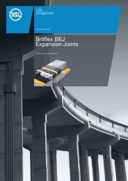
<strong>Transflex</strong><br />
<strong>Bridge</strong> <strong>Joints</strong><br />
Reinforced Elastomeric Joint System<br />
t: +44(0)191 416 1530<br />
f: +44(0)191 415 4377<br />
e: info@usluk.com
USL<br />
<strong>Bridge</strong>Care<br />
<strong>Transflex</strong><br />
<strong>Bridge</strong> <strong>Joints</strong><br />
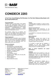
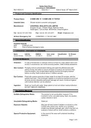
Figure 1<br />
<strong>Transflex</strong><br />
transition strip<br />
Wearing<br />
surface<br />
<strong>Transflex</strong> unit<br />
Britdex MPP<br />
waterproofing<br />
membrane<br />
<strong>Transflex</strong><br />
bedding<br />
mortar<br />
Expansion gap<br />
Uniflex<br />
membrane<br />
Anchor studs<br />
Market Leaders in Expansion<br />
Joint Technology<br />
The product in brief<br />
USL <strong>Bridge</strong>Care provides a complete service to the civil engineering<br />
industry for bridge deck protection which includes the supply and<br />
installation of expansion joints and spray applied bridge deck<br />
waterproofing membranes.<br />
The bridge expansion joint range of products caters for movements<br />
from 20mm through to 330mm.<br />
The division also manufactures and applies their Britdex MDP<br />
waterproofing system which is a rapid curing, spray applied methyl<br />
methacrylate membrane. All of USL’s products have a proven track<br />
record and comply with the latest Highways Agency requirements.<br />
Through their technical department USL <strong>Bridge</strong>Care are able<br />
to offer a complete package of services to clients and will<br />
review a particular application from initial design to final<br />
installation to ensure the selection of the most appropriate<br />
and cost effective solution.<br />
FM11022<br />
The <strong>Transflex</strong> system is registered<br />
with the UK Highways Agency, the<br />
Scottish Executive and the Welsh<br />
Assembly for use on highway<br />
bridge decks on all classes of<br />
roads and motorways. (BD 33/94:<br />
Joint Type 5 refers). The <strong>Transflex</strong><br />
system is included in the UK<br />
Highways Agency list of approved<br />
products SA1. Britflex Resin<br />
Mortar is also included in SA1<br />
as an approved material for<br />
transition strips to all types of<br />
expansion joint.<br />
USL <strong>Transflex</strong> bridge joints<br />
comprise of steel angles and<br />
a steel bridging plate system<br />
encased in a flexible elastomer.<br />
They are supplied in module<br />
lengths designed to be bolted to<br />
the structural concrete on either<br />
side of the expansion gap.<br />
A range of models are available to<br />
accommodate movement up to<br />
330mm, providing a substantially<br />
waterproof joint and a smooth<br />
running surface.<br />
• Movement accommodation<br />
up to 330mm<br />
• Corrosive resistant elastomer<br />
casing<br />
• Accommodates skew movement<br />
• Factory vulcanised kerb and<br />
skew kerb units to special order<br />
• Membrane system included for<br />
maximum waterproofing<br />
Principal applications<br />
• Highway bridge decks<br />
• Service Ramps<br />
• Multi-storey car parks<br />
03 11
USL<br />
<strong>Bridge</strong>Care<br />
<strong>Transflex</strong><br />
<strong>Bridge</strong> <strong>Joints</strong><br />
Nut<br />
Lockwasher<br />
Clipped washer<br />
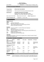
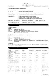
Models 400, 650, 900 & 1300<br />
Design features<br />
Design features<br />
Anchor stud<br />
D Dia<br />
Anti-skid<br />
tread design<br />
<strong>Transflex</strong> bridge joint 150, 200, 250 and 300<br />
<strong>Transflex</strong> bridge joint 400, 650, 900 and 1300<br />
Chemical capsule<br />
C<br />
Steel angle<br />
Elastomer<br />
<strong>Bridge</strong> plate<br />
system<br />
Steel angle<br />
Elastomer<br />
<strong>Bridge</strong> plate<br />
system<br />
CL<br />
Bolt hole filler<br />
CE<br />
Bolt/stud<br />
hole<br />
Typical cross section through carriageway joint<br />
W<br />
<strong>Bridge</strong> deck<br />
waterproofing<br />
membrane<br />
M<br />
Bolt/stud<br />
hole<br />
B<br />
C<br />
assumed at mid-temperature<br />
6mm allowable vertical misalignment due<br />
to beam rotation<br />
A<br />
W<br />
Transition strips to<br />
be Britflex polyureide<br />
resin<br />
R<br />
NB: Model 1300 has 8 bolt holes per unit<br />
Model 150 has 14 bolt holes per unit<br />
Nut<br />
Lockwasher<br />
Clipped washer<br />
Anchor stud<br />
Chemical capsule<br />
D Dia<br />
C<br />
CL<br />
Gap bridging<br />
plate<br />
Bolt hole filler<br />
Anti-skid<br />
tread design<br />
Tongued and<br />
grooved interlock<br />
CE<br />
D<br />
Polymer modified<br />
concrete levelling bed<br />
approx. 20mm thick<br />
Compressed<br />
sealant<br />
assume 2mm<br />
N<br />
O<br />
Uniflex<br />
secondary<br />
membrane<br />
Bedding sealant<br />
application area as<br />
10mm diam. beads<br />
Models 150, 200, 250 & 300<br />
Tongued and<br />
grooved interlock<br />
USL Translfex bridge joint models<br />
Movement Module Module Module Stud Module Max stud height Bolt Max joint width Max joint Recess Transition Bolt hole Bold hole End of unit Models<br />
accommodation length width depth diameter weight above shelf torque at mid-deck temp width depth strip width centres centre along unit to first bolt hole<br />
B A D M N O R W C CL CE<br />
38mm 1750mm 240mm 35mm 12mm 30kg 32mm 38Nm 35mm 54mm 41mm 100mm 190mm 250mm 125mm<br />
150<br />
50mm 1830mm 274mm 40mm 12mm 48kg 32mm 38Nm 51mm 76mm 46mm 100mm 220mm 305mm 152mm<br />
65mm 1830mm 356mm 46mm 16mm 68kg 40mm 95Nm 67mm 98mm 52mm 100mm 279mm 305mm 152mm<br />
76mm 1830mm 432mm 52mm 20mm 88kg 42mm 175Nm 83mm 121mm 58mm 100mm 342mm 305mm 152mm<br />
300<br />
250<br />
200<br />
102mm 1830mm 590mm 54mm 20mm 150kg 42mm 175Nm 102mm 152mm 62mm 100mm 498mm 305mm 152mm<br />
400<br />
165mm 1830mm 724mm 75mm 24mm 272kg 50mm 190Nm 121mm 203mm 81mm 125mm 618mm 305mm 152mm<br />
650<br />
230mm 1830mm 890mm 93mm 24mm 375kg 60mm 275Nm 158mm 273mm 99mm 150mm 787mm 305mm 152mm<br />
900<br />
330mm 1220mm 1204mm 127mm 30mm 451kg 70mm 300Nm 216mm 381mm 133mm 175mm 1080mm 305mm 152mm<br />
1300<br />
Note: Add 3mm to the recess depth ‘R’ when using the Uniflex secondary membrane.<br />
04<br />
05
USL<br />
<strong>Bridge</strong>Care<br />
Description<br />
The USL <strong>Transflex</strong> bridge joint<br />
system comprises of 8 No.<br />
standard models designed to<br />
accommodate movement up to<br />
330mm by shear deformation of<br />
the elastomer between the steel<br />
components.<br />
Each model incorporates steel<br />
angles designed to be bolted to<br />
the structural deck and a steel<br />
bridging plate system which spans<br />
the open joint gap.<br />
The elastomer case is highly<br />
resistant to oils, solvent spillage<br />
and the trafficked surface<br />
includes an anti-skid pattern for<br />
safety having a rubber to rubber<br />
coefficient of static friction of 0.69.<br />
Each model is specifically designed<br />
to accommodate horizontal and<br />
skew movement and will also<br />
accommodate vertical movement<br />
due to rotation of up to 6mm.<br />
<strong>Transflex</strong><br />
<strong>Bridge</strong> <strong>Joints</strong><br />
-19<br />
Model 300<br />
+19<br />
Movement mm<br />
Property Standard 20<br />
Value<br />
Technical specifications<br />
Elongation at break (min) ASTM D412 400% min<br />
Low temperature brittleness ASTM D746 Model 300 -30°C (Not brittle)<br />
Ozone resistance (After 48hrs. At 38°C ASTM D1149 -38 -25 No cracks +25 +38<br />
exposure to 50 PPHM in air sample under 20% strain)<br />
20<br />
Movement mm<br />
Resistance to permanent set (24hrs. At 70°C) ASTM D395 35% max<br />
Oil resistance ASTM D471 10<br />
+ 18%<br />
Steel Steel components manufactured to: DIN 17-100 Type ST 37-2<br />
-38 -25 +25 +38<br />
ASTM Type A36<br />
Movement mm<br />
0 90<br />
Special steel clipped washers are<br />
provided with each unit designed<br />
specifically for the <strong>Transflex</strong> joint.<br />
Stainless steel washers to the<br />
same high specification can be<br />
supplied to special order.<br />
It is important that the correct<br />
washer is used in each case.<br />
When additional waterproofing<br />
is specified a continuous length<br />
of Uniflex membrane should be<br />
bonded to the levelling bed with<br />
adhesive over the full width of the<br />
<strong>Transflex</strong> joint unit. Drain outlets<br />
will be incorporated.<br />
Rebond profiles<br />
During installation it is sometimes<br />
necessary, for practical reasons, to<br />
cut a <strong>Transflex</strong> unit on-site. In order<br />
to maintain the integrity of the joint<br />
between each module, male and<br />
female rebond profiles are available<br />
for each unit to reinstate the end<br />
configuration as required.<br />
Load kN/m<br />
Load kN/m<br />
20<br />
10<br />
Model 150<br />
Tensile strength (min) ASTM D412 10 130kg/cm² min<br />
Load kN/m<br />
0 90<br />
10<br />
-19 +19<br />
Movement mm<br />
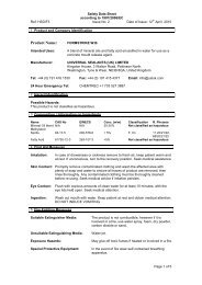
Hardness ASTM D2240 62°± 5° Shore ‘A’<br />
Manufactured to DIN 37-2<br />
150 200 250 300 400 650 900 1300<br />
a 34mm 34mm 45mm 60mm 60mm 65mm 72mm 70mm<br />
b 27mm 27mm 35mm 50mm 50mm 55mm 51mm 60mm<br />
d 14mm 14mm 17mm 21mm 21mm 25mm 25mm 31mm<br />
t 3.0mm 3.0mm 3.7mm 4.0mm 4.0mm 4.5mm 6.0mm 6.0mm<br />
Requirements<br />
Load k<br />
Steel clipped washers<br />
t<br />
Test method<br />
The profiles are available in lengths Performance<br />
100<br />
for cutting on-site together with an <strong>Transflex</strong> bridge joints are designed<br />
adhesive.<br />
to accept both horizontal and<br />
vertical loads due to traffic in 50<br />
Factory Vulcanised junctions<br />
Special factory vulcanised junctions<br />
accordance with the UK Highways<br />
Agency Technical Memorandum 90 0<br />
and kerb units are available 0to<br />
accommodate changes in level<br />
100 BD 33/94. 200 300<br />
at kerbs and central reservations,<br />
in addition, standard units are<br />
capable of being modified on-site<br />
to accommodate some level<br />
The graphs illustrated opposite are<br />
an indication of the horizontal load<br />
required to deflect each <strong>Transflex</strong><br />
joint.<br />
changes.<br />
Load kN/m<br />
20<br />
10<br />
Load kN/m<br />
Model 200<br />
-50 -25 20 +25 20 20 +50<br />
Movement mm10<br />
10<br />
400<br />
20 Model Model<br />
20<br />
Model 300 300 300<br />
-38 -25 -38 -25 +25 +38+25<br />
+38<br />
Movement Movement mm Model mm<br />
900<br />
-38 -38 -25 -38 -25 -25 +25 +25 +38+25<br />
+38<br />
Movement Movement Movement 20mmmm<br />
mm<br />
20 Model Model 20<br />
Model 400 400 400<br />
-83 -75 -50 -25<br />
20 20<br />
+25 +50 +75 +83<br />
20<br />
Movement 10mm<br />
10<br />
-50 -25 -50 -25 +25 +50+25<br />
+50<br />
Movement Movement mm mm<br />
-50 -50-25 -50-25 -25 +25 +25 +50+25<br />
+5020<br />
Movement Movement Movement mm mm mm<br />
20 Model Model 20<br />
Model 900 900<br />
0 90900<br />
-165 -150 -127 -100 -75 -50 -25 +25 +50 +75 +100 +127 +150 +165<br />
Movement mm<br />
Model 1300 Model 1300<br />
-114 -100 -114 -75-100 -50 -75<br />
-25-50 -25 +25 +50 +25<br />
+75+50 +100 +75<br />
+114 +100 +114<br />
200<br />
Movement Movement mm mm<br />
-114 -114 -100 -114 -100 -75-100 -50 -50 -75 -25-50 -25 -25 +25 +25 +50 +25 +50 +75+50 +75 +100 +100 +75 +114 +100 +114 +114<br />
150<br />
Movement Movement Movement mm mm mm<br />
100<br />
06 10 10<br />
07<br />
10<br />
Load Load kN/m kN/m<br />
Load Load kN/m kN/m<br />
Model 10 150 Model 150<br />
20 Model Model<br />
20<br />
Model 150 150 150<br />
Model 300 Model 10300<br />
20 Model Model<br />
20<br />
Model 200 200 200<br />
-32-25 +25<br />
20<br />
+32 20 Model 20 650<br />
Movement mm 10 10<br />
20<br />
10 10 10<br />
10<br />
10<br />
-19 -19 +19 +19<br />
-25 -25 +25 +25<br />
Movement Movement mm mm<br />
Movement Movement mm mm<br />
-19 -19 -19 +19 +19 +19 -25 -25 -25 +25 +25 +25<br />
Model 400<br />
Movement Movement mm mmModel 650<br />
Movement mm<br />
Movement Movement Movement mm mm mm<br />
-50 -25 +25 +50<br />
-83 -75 -50 -25 +25 +50 +75 +83<br />
Movement mm 20<br />
Movement mm<br />
Load kN/m<br />
Load kN/m<br />
10<br />
Load kN/m<br />
-25 +25 Model 20400<br />
20<br />
Movement mm<br />
10<br />
20<br />
10 10 10<br />
20<br />
10<br />
Load kN<br />
10<br />
Load kN/m<br />
-25 +25<br />
Movement mm<br />
Load kN/m<br />
Load kN/m<br />
350<br />
300<br />
d<br />
a<br />
250<br />
b<br />
400<br />
200<br />
350<br />
150<br />
300<br />
100<br />
250<br />
50<br />
Technical Data 200<br />
90 0<br />
0 100 200<br />
150<br />
300<br />
30<br />
20<br />
10<br />
Load kN/m<br />
10<br />
10<br />
Load kN/m<br />
Load kN/m<br />
Load kN/m<br />
10<br />
Load kN/m<br />
20<br />
Load kN/m<br />
10<br />
Model 250<br />
Load kN/m<br />
Load kN/m<br />
Load Load kN/m kN/m<br />
Load Load kN/m kN/m<br />
Model 200 Model 200<br />
50 90 500<br />
50 90<br />
20 0 0 100 100<br />
200 200 300 300<br />
90 90<br />
0 90 0 0<br />
0 0 0 100 100 100 200 200 200 300 300 300<br />
Model 101300<br />
Load kN/m<br />
Model 400 Model 400<br />
Model 900<br />
0 90 0 400 400<br />
-114 90 -100 -75 -50 -25 +25 +50 +75 +100 +114<br />
20<br />
Movement mm<br />
0 900 90<br />
400 400 350400<br />
0 90<br />
350<br />
10<br />
350 350 300350<br />
300<br />
30<br />
Load k<br />
Load kN/m<br />
Load kN/m<br />
300 300 250300<br />
250<br />
-114 -100 -75 -50 -25 +25 +50 +75 250+100 200250<br />
+114200<br />
Movement mm<br />
200 200 150200<br />
150<br />
Model 1300<br />
10<br />
Load/movement curves for USL <strong>Transflex</strong><br />
bridge joints<br />
-32-25 +25+32<br />
Movement mm<br />
150 150 100150<br />
100<br />
100 100 50 100<br />
-165 -150 -127 -100 -75 -50 -25 +25 +50 +75 +100 +127 +150<br />
20<br />
+165 20 20<br />
Movement mm<br />
10<br />
Load kN/m<br />
Load kN/m<br />
10<br />
Load kN/m<br />
10<br />
10<br />
Load kN/m<br />
50<br />
0<br />
Load Load kN/m kN/m<br />
Load Load kN/m kN/m<br />
Load Load kN/m kN/m<br />
Load kN/m<br />
30 Model Model Model 1300 1300<br />
30<br />
1300<br />
30 30 30<br />
20<br />
Load kN/m<br />
Load kN/m<br />
Load kN/m<br />
20 20 20<br />
10<br />
10<br />
20<br />
10<br />
Load kN/m<br />
10<br />
Load kN/m<br />
Load kN/m<br />
10<br />
20 Model Model<br />
20<br />
Model 250 250 250<br />
20 Model Model 20<br />
Model 650 650 650<br />
-19 +19<br />
Movement<br />
20 20 mm<br />
20<br />
10 10<br />
Load Load kN/m kN/m<br />
Model 250 Model 250<br />
Model 650 Model 650<br />
Model 300 -83 -75 -50 -83 -75<br />
-25 -50 -25 +25 +50 +25<br />
+75 +83 +50 +75<br />
+<br />
Movement Movement Model<br />
mm mm<br />
400<br />
-83 -83 -75 -75 -83 -50 -75 -50 -25-50 -25 +25 +25 +50 +25 +50 +75 +75 +50 +83 +75 +83<br />
20 +83<br />
Movement Movement Movement mm mm mm<br />
Graph of maximum movements absorbed by<br />
the different modules according to the angle<br />
formed by the joint with the longitudinal axis<br />
of the floor<br />
Model 900 Model 900<br />
10<br />
Load kN/m<br />
20 20 20<br />
10<br />
10<br />
Load kN/m<br />
10<br />
Load kN/m<br />
10<br />
Load kN/m<br />
10<br />
10<br />
10<br />
-32-25 -32 -25 +25+32<br />
+25<br />
+32<br />
Movement Movement mm mm<br />
-32-25 -32-25 -32-25 +25 +25 +32 +32 +25+32<br />
Model<br />
Movement Movement<br />
150<br />
Movement mm mm mm<br />
Model 200<br />
20<br />
10<br />
Load kN/m<br />
10<br />
Load kN/m<br />
10<br />
-38 -25 +25 +38<br />
Movement mm<br />
Load kN/m<br />
20<br />
10<br />
Load kN/m<br />
-25 +25<br />
Movement mm<br />
10<br />
90<br />
0 100 200 300<br />
Component parallel with the joint mm<br />
-50<br />
400<br />
350<br />
300<br />
250<br />
50<br />
0<br />
Notation:<br />
- = Compression<br />
+ = Extension<br />
-25<br />
Movemen<br />
Component perpendicular with the joint mm<br />
Load kN/m<br />
30<br />
20<br />
10
USL<br />
<strong>Bridge</strong>Care<br />
<strong>Transflex</strong><br />
<strong>Bridge</strong> <strong>Joints</strong><br />
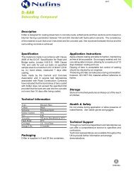
Kerb upstand units<br />
Optional - male or<br />
female tongue and<br />
groove<br />
Male or female<br />
tongue and groove<br />
Deck<br />
Temperature<br />
Calculated<br />
maximum<br />
At time of<br />
installation<br />
<strong>Transflex</strong> 200<br />
compressed<br />
by 20mm<br />
Included<br />
angle<br />
Skew<br />
angle<br />
Dimension<br />
to suit<br />
Examples of a factory vulcanised kerb<br />
unit for models 150, 200, 250 & 300<br />
Examples of a factory vulcanised skew<br />
kerb upstand<br />
Included<br />
angle<br />
Assumed<br />
mid-point<br />
<strong>Transflex</strong> 200<br />
at mid-point<br />
position<br />
Included<br />
angle<br />
Male or female<br />
tongue and groove<br />
Examples of change of level of junction<br />
for models 400, 650, 900 & 1300<br />
Calculated<br />
minimum<br />
<strong>Transflex</strong> 200<br />
extended by<br />
25mm<br />
Examples of a factory vulcanised kerb unit<br />
for models 400, 650, 900 & 1300<br />
Optional - male or<br />
female tongue and<br />
groove<br />
a b c d<br />
Installation<br />
width<br />
Factory Vulcanised junctions<br />
Kerb Units<br />
On-site modification<br />
Installation<br />
As part of a bridge joint installation<br />
scheme factory vulcanised<br />
junctions are available to<br />
accommodate the change in<br />
level at kerbs, footways and at<br />
the central reservation subject to<br />
special order and design detail.<br />
The junctions available include<br />
kerb units, skew kerb units and<br />
change of level units, each factory<br />
vulcanised to maintain high quality<br />
standards and integrity of the seal.<br />
Change of level junctions are<br />
available factory vulcanised to meet<br />
the requirements for changing level<br />
from road deck to footway.<br />
The junctions are fabricated such<br />
that the change in level from road<br />
to footway takes place behind the<br />
kerb line. Leg lengths, the included<br />
angles and the male or female end<br />
configurations should be specified<br />
at the time of order.<br />
Whilst factory vulcanised change of<br />
level junctions should be used as<br />
far as possible it may be necessary<br />
to modify standard units on-site<br />
to accommodate changes of level<br />
from road to footway.<br />
This is achieved by cutting and<br />
notching the steel bridging system<br />
and steel angles and bending<br />
the units through 30°. The point<br />
of change of level from road to<br />
footway taking place behind the<br />
kerb line. The void in the kerb line<br />
being protected with galvanised<br />
steel cover plate.<br />
Details on change of level<br />
modifications available from<br />
<strong>Universal</strong> <strong>Sealants</strong> (UK) Ltd.<br />
<strong>Transflex</strong> temperature<br />
adjustment guide<br />
It will often be necessary to<br />
pre-compress or pre-extend the<br />
<strong>Transflex</strong> joint to pre-set the joint<br />
unit to suit the relative position of<br />
the structural expansion joint in the<br />
bridge deck.<br />
At the time of installation<br />
therefore knowing the mean<br />
deck temperature range and the<br />
movement to be accommodated,<br />
the amount of pre-compression or<br />
pre-extension can be taken off a<br />
graph prepared in the manner of<br />
the example illustrated.<br />
NB.<br />
1. Example based on model 200<br />
(274mm wide)<br />
2. The example assumes a<br />
total design movement<br />
accommodation requirement<br />
of + and – 25mm from the mid<br />
point position.<br />
3. The installation temperature<br />
requires that the joint be<br />
compressed to 254mm overall<br />
width – prior to installation.<br />
4. Hence the new bolt hold centres<br />
“C” to be drilled in the structural<br />
concrete will be 199mm instead<br />
of 219mm.<br />
5. Maximum movement of joint<br />
+ and – 25mm.<br />
6. Actual movement required<br />
+ and – 25mm<br />
Key:<br />
a. Maximum compression<br />
274 - 25 = 249mm<br />
b. Compressed width for<br />
installation 254mm<br />
c. Actual module width 274mm<br />
d. Maximum extension<br />
274 + 25 = 299mm<br />
Site installation – for concrete<br />
decks<br />
A flat and level monolithic haunch<br />
or recess should be formed in the<br />
structural deck to accommodate<br />
the <strong>Transflex</strong> joint and the<br />
transition strips.<br />
At the design stage care should be<br />
taken to locate the reinforcement<br />
avoiding the position of the bridge<br />
joint anchor studs.<br />
In the interest of achieving a<br />
smooth traffic ride over the joint,<br />
the wearing course should be<br />
machine laid continuously over the<br />
structural joint and subsequently<br />
removed just prior to installing the<br />
bridge joint.<br />
The removal of the surfacing over<br />
the joint in the deck is facilitated by<br />
the location of the plywood bond<br />
breaker of a width just under the<br />
combined width of the joint and<br />
the transition strips prior to the<br />
surfacing being laid. At the time<br />
of installation dependent upon<br />
mean deck temperature it may<br />
be necessary to pre-compress or<br />
pre-extend the <strong>Transflex</strong> joint unit<br />
to suit the relative position of the<br />
structural expansion joint in the<br />
bridge deck.<br />
The installation width of the joint<br />
may be determined using graphical<br />
means illustrated in the example<br />
under the heading “Temperature<br />
Adjustment Guide”.<br />
Once the <strong>Transflex</strong> module<br />
installation width and the new bolt<br />
hole centres have been determined<br />
the joint module can be adjusted in<br />
width accordingly.<br />
08<br />
09
USL<br />
<strong>Bridge</strong>Care<br />
<strong>Transflex</strong><br />
<strong>Bridge</strong> <strong>Joints</strong><br />
Installation (continued)<br />
Installation (continued)<br />
Additional Information<br />
<strong>Universal</strong> <strong>Sealants</strong> (U.K) Ltd<br />
The surfacing may then be sawn<br />
and removed to the dimension<br />
equivalent to the installation<br />
width of the joint plus the two<br />
transition strips. The exposed<br />
concrete should be scabbled<br />
and the final level of the bed<br />
adjusted using a polymer modified<br />
screed approximately 20mm thick<br />
maintaining the recess depth<br />
“R” ie 46mm in the case of<br />
model 200.<br />
The bridge joint modules centred<br />
over the expansion joint in the deck<br />
may then be used as templates for<br />
the pilot holes thus determining the<br />
final position of the bolt holes or by<br />
use of a prepared template.<br />
The final bolt holes should be<br />
drilled and studs installed using<br />
chemical fixing anchors. Each<br />
bridge joint unit may then be laid<br />
into position over the studs on<br />
beads of bedding sealant. The<br />
plain clipped washers supplied<br />
with each unit are then located,<br />
and the assembly bolted down.<br />
Subsequent modules should then<br />
be located and fixed in the same<br />
way, the sealant first being applied<br />
to the tongue and groove edges<br />
of each unit prior to jacking into<br />
position to ensure a substantially<br />
waterproof junction.<br />
The fixing nuts should be<br />
tightened to the rate indicated<br />
for each model and the polyureide<br />
resin transition strips laid level with<br />
the wearing surface but finished<br />
slightly higher (3mm) than that of<br />
the top of the bridge joint module.<br />
Following final torque checks<br />
on the fixing nut, the bolt holes<br />
should be filled with <strong>Transflex</strong> Bolt<br />
Hole Sealant to protect the stud<br />
against corrosion.<br />
Waterproof Installations<br />
For improved waterproofing<br />
it is necessary to incorporate<br />
Uniflex Secondary Membrane<br />
which should be fixed with epoxy<br />
adhesive to the top surface of the<br />
levelling screed over the full width<br />
of the <strong>Transflex</strong> Unit prior to the<br />
sealant bedding application. The<br />
recess depth R should be adjusted<br />
by +3mm.<br />
Further Information<br />
1. USL <strong>Transflex</strong><br />
Installation Manual<br />
The detailed Installation Guide<br />
sets out the recommended<br />
installation procedure for<br />
<strong>Transflex</strong> bridge joints.<br />
2. USL <strong>Transflex</strong><br />
Product Schedules<br />
Detailed product schedules for<br />
each joint module set out the<br />
components available against<br />
each <strong>Transflex</strong> model type.<br />
Ancillary materials<br />
and equipment<br />
Materials:<br />
Studs and Chemical fixing<br />
anchors – See chart under heading<br />
“Description for recommended<br />
diameter and type”<br />
Uniflex membrane for waterproof<br />
applications.<br />
Uniseal 120, one part polysulphide<br />
for bedding and sealing each<br />
module.<br />
<strong>Transflex</strong> Bolt Hole Sealant for<br />
filling bolt holes.<br />
<strong>Transflex</strong> Levelling Screed polymer<br />
modified mortar for use as a<br />
levelling screed or bed.<br />
Britflex polyureide resin for forming<br />
transition strips between road<br />
wearing surfaces and the module<br />
joint.<br />
Equipment:<br />
Extension/compression tool for<br />
adjusting and pre-setting the<br />
module joint to suit temperature/<br />
joint gap at time of installation.<br />
Rotary percussion drill; Forced<br />
action mixer ‘G’ Gun; Torque<br />
spanner; Jacking equipment.<br />
There are no health hazards<br />
associated with USL <strong>Transflex</strong> in<br />
normal use.<br />
Ancillary materials<br />
Health and safety data sheets<br />
for Uniseal 120, <strong>Transflex</strong> Bolt<br />
Hole Sealant, <strong>Transflex</strong> Levelling<br />
Screed are available separately<br />
from USL’s Technical Service<br />
Department.<br />
Important Note<br />
Whilst all reasonable care is<br />
taken in compiling technical<br />
data on the company’s products<br />
all recommendations or<br />
suggestions regarding the use of<br />
such products are made without<br />
guarantee since the conditions<br />
of use are beyond the control of<br />
the company. It is the customer’s<br />
responsibility to satisfy himself<br />
that each product is fit for the<br />
purpose for which he intends to<br />
use it and that the actual<br />
conditions of use are suitable.<br />
USL <strong>Bridge</strong>Care<br />
A division of <strong>Universal</strong> <strong>Sealants</strong><br />
(UK) Limited<br />
Offering the complete service for<br />
bridge deck protection.<br />
• Expansion joints<br />
• Spray membranes<br />
• Concrete repairs<br />
www.usluk.com<br />
USL StructureCare<br />
A division of <strong>Universal</strong> <strong>Sealants</strong><br />
(UK) Limited<br />
Supply and installation of<br />
expansion joints, protective<br />
coatings, concrete repairs and<br />
joint sealants to car parks,<br />
elevated structures and the<br />
construction industry.<br />
www.structurecare.com<br />
Nufins<br />
A division of <strong>Universal</strong> <strong>Sealants</strong><br />
(UK) Limited<br />
Manufacturers and suppliers<br />
of formulated products for civil<br />
engineering, construction, repair<br />
and refurbishment.<br />
www.nufins.com<br />
Visul Systems<br />
A division of <strong>Universal</strong> <strong>Sealants</strong><br />
(UK) Limited<br />
A manufacturer, supplier and<br />
installer of surface mounted<br />
tactile paving.<br />
www.visulsystems.com<br />
10