MBX-4 User Guide - TerraSond
MBX-4 User Guide - TerraSond
MBX-4 User Guide - TerraSond

You also want an ePaper? Increase the reach of your titles
YUMPU automatically turns print PDFs into web optimized ePapers that Google loves.
<strong>MBX</strong>-4<br />
<strong>User</strong> <strong>Guide</strong><br />
Part No. 875-0188-000 Rev. A1
This device complies with Part 15 of the FCC rules. Operation is subject to the following<br />
two conditions:<br />
• This device may not cause harmful interference.<br />
• This device must accept any interference received, including interference, that may<br />
cause undesired operation.<br />
Copyright Notice<br />
Hemisphere GPS, Inc. Precision GPS Applications<br />
© Copyright Hemisphere GPS, Inc. 2007. All rights reserved.<br />
No part of this manual may be reproduced, transmitted, transcribed, stored in a retrieval<br />
system or translated into any language or computer language, in any form or by any<br />
means, electronic, mechanical, magnetic, optical, chemical, manual or otherwise, without<br />
the prior written permission of Hemisphere GPS.<br />
Trademarks<br />
Hemisphere GPS and the Hemisphere GPS logo, Satloc and the Satloc logo, Mapstar, Air<br />
Star Outback Guidance and eDrive are trademarks of Hemisphere GPS, Inc., Other<br />
trademarks are the properties of their respective owners.<br />
Notice to Customers<br />
Contact your local dealer for technical assistance. To find the authorized dealer near you,<br />
call or write us at:<br />
Hemisphere GPS<br />
4110 9th Street S.E.<br />
Calgary, AB Canada<br />
T2G-3C4<br />
Telephone number:<br />
Fax number:<br />
E-mail address:<br />
(403) 259-3311<br />
(403) 259-8866<br />
sales@hemispheregps.com<br />
www.hemispheregps.com
Warranty Notice<br />
Covered Products<br />
This warranty covers all products manufactured by Hemisphere GPS, Inc.(the "Products").<br />
Hemisphere GPS Limited Warranty<br />
Hemisphere GPS hereby warrants solely to the end purchaser of the Products, subject to the exclusions and<br />
procedures set forth herein below, that the Products sold to such end purchaser shall be free, under normal use and<br />
maintenance, from defects in material and workmanship for a period of 12 months from delivery to such end<br />
purchaser. Repairs and replacement components are warranted, subject to the exclusions and procedures set forth<br />
below, to be free, under normal use and maintenance, from defects in material and workmanship for 90 days from<br />
performance or delivery, or for the balance of the original warranty period, whichever is greater.<br />
Purchaser's Exclusive Remedy<br />
The end purchaser's exclusive remedy under this warranty shall be limited to the repair or replacement, at the option<br />
of Hemisphere GPS, of any defective Products or components thereof. The end user shall notify Hemisphere GPS or<br />
a Hemisphere GPS approved service center immediately of any claimed defect. Repairs shall be made through a<br />
Hemisphere GPS approved service center only.<br />
Exclusions<br />
Hemisphere GPS does not warrant damage occurring in transit or due to misuse, abuse, improper installation,<br />
neglect, lightning (or other electrical discharge) or fresh/salt water immersion of Products. Repair, modification or<br />
service of Hemisphere GPS products by any party other than a Hemisphere GPS approved service center shall render<br />
this warranty null and void. Hemisphere GPS does not warrant claims asserted after the end of the warranty period.<br />
Hemisphere GPS does not warrant or guarantee the precision or accuracy of positions obtained when using<br />
Products. Products are not intended for primary navigation or for use in safety of life applications. The potential<br />
accuracy of Products as stated in Hemisphere GPS literature and/or Product specifications serves to provide only an<br />
estimate of achievable accuracy based on:<br />
• Specifications provided by the US Department of Defense for GPS Positioning,<br />
• DGPS service provider performance specifications.<br />
Hemisphere GPS reserves the right to modify Products without any obligation to notify, supply or install any<br />
improvements or alterations to existing Products.<br />
No Other Warranties<br />
THE FOREGOING WARRANTY IS EXCLUSIVE OF ALL OTHER WARRANTIES, WHETHER WRITTEN, ORAL, IMPLIED<br />
OR ARISING BY STATUTE, COURSE OF DEALING OR TRADE USAGE, IN CONNECTION WITH THE DESIGN, SALE,<br />
INSTALLATION, SERVICE OR USE OF ANY PRODUCTS OR ANY COMPONENTS THEREOF, INCLUDING, BUT NOT<br />
LIMITED TO, ANY WARRANTY OF MERCHANTABILITY OR FITNESS FOR A PARTICULAR PURPOSE.<br />
Limitation of Liability<br />
THE EXTENT OF HEMISPHERE GPS' LIABILITY FOR DAMAGES OF ANY NATURE TO THE END PURCHASER OR ANY<br />
OTHER PERSON OR ENTITY WHETHER IN CONTRACT OR TORT AND WHETHER TO PERSONS OR PROPERTY<br />
SHALL IN NO CASE EXCEED, IN THE AGGREGATE, THE COST OF CORRECTING THE DEFECT IN THE PRODUCT OR,<br />
AT HEMISPHERE GPS' OPTION, THE COST OF REPLACING THE DEFECTIVE ITEM. IN NO EVENT WILL HEMISPHERE<br />
GPS BE LIABLE FOR ANY LOSS OF PRODUCTION, LOSS OF PROFITS, LOSS OF USE OR FOR ANY SPECIAL,<br />
INDIRECT, INCIDENTAL, CONSEQUENTIAL OR CONTINGENT DAMAGES, EVEN IF HEMISPHERE GPS HAS BEEN<br />
ADVISED OF THE POSSIBILITY OF SUCH DAMAGES. WITHOUT LIMITING THE FOREGOING, HEMISPHERE GPS<br />
SHALL NOT BE LIABLE FOR ANY DAMAGES OF ANY KIND RESULTING FROM INSTALLATION, USE, QUALITY,<br />
PERFORMANCE OR ACCURACY OF ANY PRODUCTS.
Governing Legislation<br />
To the greatest extent possible, this warranty shall be governed by the laws of the State of Arizona. In the event that<br />
any provision hereof is held to be invalid by a court of competent jurisdiction, such provision shall be severed from<br />
this warranty and the remaining provisions shall remain in full force and effect.<br />
Obtaining Warranty Service<br />
In order to obtain warranty service, the end purchaser must bring the Product to a Hemisphere GPS approved service<br />
center along with the end purchaser's proof of purchase. For any questions regarding warranty service or to obtain<br />
information regarding the location of any of Hemisphere GPS' approved service centers, contact Hemisphere GPS at<br />
the following address:<br />
Hemisphere GPS<br />
7560 East Redfield Road, Suite B<br />
Scottsdale, Arizona 85260<br />
Phone 480.348.9919 Fax 480.348.6370<br />
techsupport@hemispheregps.com<br />
http://www.hemispheregps.com
<strong>MBX</strong>-4 <strong>User</strong> <strong>Guide</strong><br />
Table of Contents<br />
1: Introduction . . . . . . . . . . . . . . . . . . . . . . 1<br />
GPS . . . . . . . . . . . . . . . . . . . . . . . . . . . . . . . . . . . .2<br />
How it Works 2<br />
GPS Services 3<br />
Differential GPS . . . . . . . . . . . . . . . . . . . . . . . . . .4<br />
How it Works 4<br />
Real-Time DGPS 4<br />
DGPS Format 5<br />
Radiobeacon DGPS Service 5<br />
Radiobeacon Range 5<br />
Radiobeacon Reception 7<br />
Radiobeacon DGPS 7<br />
Radiobeacon Coverage 8<br />
Factors Affecting Positioning Accuracy . . . . . .10<br />
<strong>MBX</strong>-4 Beacon Receiver Information . . . . . . . . .13<br />
MGL-4 Combined GPS / Magnetic Field Antenna 14<br />
2: Installation . . . . . . . . . . . . . . . . . . . . . . 15<br />
System Parts List . . . . . . . . . . . . . . . . . . . . . . . .16<br />
i
Receiver Layout and Connections . . . . . . . . . . .17<br />
Installing the Receiver . . . . . . . . . . . . . . . . . . . .19<br />
Receiver Placement 19<br />
Environmental Considerations 19<br />
Power Considerations 20<br />
Grounding the Receiver 21<br />
Connecting the Receiver To External Devices 21<br />
RS-232 and RS-422 Operation 24<br />
Installing the Antenna . . . . . . . . . . . . . . . . . . . .26<br />
Antenna Placement to Optimize Reception 26<br />
MGL-4 Combined GPS/Beacon Antenna 27<br />
Routing and Securing the Antenna Cable 27<br />
Magnetic Mount 29<br />
Internal Signal Splitter . . . . . . . . . . . . . . . . . . . .30<br />
3: <strong>MBX</strong>-4 Configuration and Operation . . 33<br />
Front Display and Keypad . . . . . . . . . . . . . . . . .34<br />
Lock Status 35<br />
Factory Default Settings . . . . . . . . . . . . . . . . . . 36<br />
Tune Modes . . . . . . . . . . . . . . . . . . . . . . . . . . . .37<br />
Automatic Beacon Search (ABS) Mode 37<br />
Manual Mode 38<br />
<strong>MBX</strong>-4 Display Modes . . . . . . . . . . . . . . . . . . . .39<br />
ii
<strong>MBX</strong>-4 <strong>User</strong> <strong>Guide</strong><br />
BX Mode 39<br />
BX-E Mode 39<br />
<strong>MBX</strong>-4 Menu System . . . . . . . . . . . . . . . . . . . . .41<br />
Start-Up Sequence 42<br />
Beacon Status 42<br />
Setup 44<br />
Position Status (BX-E Mode Only) 48<br />
Satellites (BX-E Mode Only) 50<br />
Menu System Shortcuts 51<br />
<strong>MBX</strong>-4 Receiver Performance - SNR Reading . . .53<br />
Operation of <strong>MBX</strong>-4 with Garmin GPS . . . . . . . 54<br />
Configuring the Receiver . . . . . . . . . . . . . . . . . .55<br />
Change Baud Rate 55<br />
Change Frequency and MSK Rate 55<br />
Select a Beacon By Name 55<br />
Set to Automatic Beacon Search Mode 56<br />
Change Display Mode 56<br />
4: NMEA 0183 Interface . . . . . . . . . . . . . . 59<br />
Interface Protocols . . . . . . . . . . . . . . . . . . . . . . .60<br />
Description of NMEA 0183 60<br />
NMEA Message Elements 61<br />
Hemisphere GPS’ DGPS Command Center 61<br />
iii
<strong>MBX</strong>-S Supported Messages 62<br />
Response Message 63<br />
NMEA 0183 Commands . . . . . . . . . . . . . . . . . . .64<br />
Standard Commands 64<br />
Proprietary Commands 66<br />
NMEA 0183 Queries . . . . . . . . . . . . . . . . . . . . . .70<br />
Standard Queries 70<br />
Proprietary Queries 71<br />
5: Troubleshooting . . . . . . . . . . . . . . . . . . 73<br />
Troubleshooting . . . . . . . . . . . . . . . . . . . . . . . .74<br />
Appendices . . . . . . . . . . . . . . . . . . . . . . . 77<br />
Appendix A - Specifications . . . . . . . . . . . . . . . .78<br />
Appendix B - Beacon Information . . . . . . . . . . . .82<br />
Further Reading . . . . . . . . . . . . . . . . . . . . . . . . .83<br />
iv
1: Introduction<br />
GPS<br />
Differential GPS<br />
DGPS Format<br />
Factors Affecting Positioning Accuracy<br />
<strong>MBX</strong>-4 Beacon Receiver Information<br />
MGL-4 Combined GPS/Magnetic Field Antenna
1: Introduction<br />
GPS<br />
This chapter provides a brief overview of GPS, differential GPS beacon<br />
technology, and a description of the <strong>MBX</strong>-4 receiver, antenna, and<br />
mount.<br />
The United States Department of Defense (DoD) operates a reliable, 24<br />
hour a day, all weather Global Positioning System (GPS).<br />
Navstar, the original name given to this geographic positioning and<br />
navigation tool, includes a constellation of 24 satellites (plus active<br />
spares) orbiting the Earth at an altitude of approximately 13,670 miles<br />
(22,000 kilometers).<br />
How it Works<br />
These satellites transmit coded information to GPS users at UHF (1.575<br />
GHz) frequencies that allows user equipment to calculate a range to<br />
each satellite. GPS is essentially a timing system - ranges are calculated<br />
by timing how long it takes for the GPS signal to reach the user’s GPS<br />
antenna.<br />
To calculate a geographic position, the GPS receiver uses a complex<br />
algorithm incorporating satellite coordinates and ranges to each<br />
satellite. Reception of any four or more of these signals allows a GPS<br />
receiver to compute 3D coordinates. Tracking of only three satellites<br />
reduces the position fix to 2D coordinates (horizontal with fixed<br />
vertical).<br />
The GPS receiver calculates its position with respect to the phase center<br />
of the GPS antenna.<br />
2
<strong>MBX</strong>-4 <strong>User</strong> <strong>Guide</strong><br />
GPS Services<br />
The positioning accuracy offered by GPS varies depending upon the<br />
type of service and equipment available. For security reasons, two GPS<br />
services exist: the Standard Positioning Service (SPS) and the Precise<br />
Positioning Service (PPS). The US Department of Defense (DoD)<br />
reserves the PPS for use by its personnel and authorized partners. The<br />
DoD provides the SPS free of charge, worldwide, to all civilian users.<br />
In order to maintain a strategic advantage, the US DoD has a policy to<br />
artificially degrades the performance of the SPS. Currently the level of<br />
this degradation has been set to zero, however, in years past, this<br />
intentional error limited the positioning accuracy of the SPS to 100<br />
meters 95% of the time. This policy is called Selective Availability (SA).<br />
Without SA, autonomous positioning accuracy is currently about 10 to<br />
15 m 95% of the time.<br />
For many positioning and navigation applications, an accuracy of 10 to<br />
15 meters is insufficient, and differential positioning techniques must be<br />
employed.<br />
3
1: Introduction<br />
Differential GPS<br />
The purpose of differential GPS (DGPS) is to remove the effects of SA (if<br />
present), atmospheric errors, timing errors, and satellite orbit errors,<br />
while enhancing system integrity.<br />
How it Works<br />
DGPS involves setting up a reference GPS receiver at a point of known<br />
coordinates. This receiver makes distance measurements, in real-time,<br />
to each of the GPS satellites. The measured ranges include the errors<br />
present in the system. The base station receiver calculates what the true<br />
range should be without errors, knowing its coordinates and those of<br />
each satellite. The difference between the known and measured range<br />
for each satellite is the range error. This error is the amount that needs<br />
to be removed from each satellite distance measurement in order to<br />
correct for errors present in the system.<br />
Real-Time DGPS<br />
The base station transmits the range error corrections to remote<br />
receivers in real-time. The remote receiver corrects its satellite range<br />
measurements using these differential corrections, yielding a much<br />
more accurate position. This is the predominant DGPS strategy used for<br />
a majority of real-time applications. Positioning using corrections<br />
generated by DGPS radiobeacons will provide a horizontal accuracy of 1<br />
to 5 meters with a 95% confidence. More sophisticated, short-range<br />
DGPS systems (10 to 15 km) can achieve centimeter-level accuracy, but<br />
are very expensive and often limited to precise survey applications due<br />
to technical constraints on their use.<br />
4
<strong>MBX</strong>-4 <strong>User</strong> <strong>Guide</strong><br />
DGPS Format<br />
For manufacturers of GPS equipment, commonality is essential to<br />
maximize the utility and compatibility of a product. The governing<br />
standard associated with GPS is the Interface Control Document,<br />
ICD-GPS-200, maintained by the US DoD. This document provides the<br />
message and signal structure information required to access GPS.<br />
Like GPS, DGPS data and broadcast standards exist to ensure<br />
compatibility between DGPS networks, and associated hardware and<br />
software. The Radio Technical Commission for Maritime Services<br />
Special Committee 104 has developed the primary DGPS standard<br />
associated with radiobeacon DGPS, designated RTCM SC-104 V2.2.<br />
Various broadcast standards may exist for the beacon networks<br />
installed internationally, controlled by their respective operating<br />
authority. The United States Coast Guard maintains a broadcast<br />
standard that is referenced in the Further Reading section of this<br />
manual.<br />
Radiobeacon Range<br />
The broadcasting range of a 300 kHz beacon is dependent upon a<br />
number of factors including transmission power, free space loss,<br />
ionospheric state, surface conductivity, ambient noise, and atmospheric<br />
losses.<br />
The strength of a signal decreases with distance from the transmitting<br />
station, due in large part to spreading loss. This loss is a result of the<br />
signal’s power being distributed over an increasing surface area as the<br />
signal radiates away from the transmitting antenna.<br />
The expected range of a broadcast also depends upon the conductivity<br />
of the surface over which it travels. A signal will propagate further over<br />
a surface with high conductivity than over a surface with low<br />
conductivity. Lower conductivity surfaces such as dry, infertile soil,<br />
5
1: Introduction<br />
absorb the power of the transmission more than higher conductivity<br />
surfaces, such as sea water or arable land.<br />
A radiobeacon transmission has three components: a direct line of sight<br />
wave, a ground wave, and a sky wave. The line of sight wave is not<br />
significant beyond visual range of the transmitting tower, and does not<br />
have a substantial impact upon signal reception.<br />
The ground wave portion of the signal propagates along the surface of<br />
the earth, losing strength due to spreading loss, atmospheric refraction<br />
and diffraction, and attenuation by the surface over which it travels<br />
(dependent upon conductivity).<br />
The portion of the beacon signal broadcast skywards is known as the<br />
sky wave. Depending on its reflectance, the sky wave may bounce off<br />
the ionosphere and back to Earth causing reception of the ground wave<br />
to fade. Fading occurs when the ground and sky waves interfere with<br />
each other. The effect of fading is that reception may fade in and out.<br />
However, this problem usually occurs in the evening when the<br />
ionosphere becomes more reflective and usually on the edge of<br />
coverage areas. Fading is not usually an issue with overlapping<br />
coverage areas of beacons and their large overall range.<br />
Atmospheric attenuation plays a minor part in signal transmission<br />
range, as it absorbs and scatters the signal. This type of loss is the least<br />
significant of those described.<br />
6
<strong>MBX</strong>-4 <strong>User</strong> <strong>Guide</strong><br />
Radiobeacon Reception<br />
Various sources of noise affect beacon reception, and include:<br />
• Engine noise<br />
• Alternator noise<br />
• Noise from Power lines<br />
• DC to AC inverting equipment<br />
• Electric devices such as CRT’s electric motors, and solenoids<br />
Noise generated by this type of equipment can mask the beacon signal,<br />
reducing or impairing reception. The “Antenna Placement to Optimize<br />
Reception” section on page 24 presents an effective procedure to<br />
minimize impact of local noise on beacon reception when using this<br />
correction service.<br />
Radiobeacon DGPS<br />
Radiobeacons conforming to the standards of the International<br />
Association of Lighthouse Authorities broadcast a limited selection of<br />
RTCM SC-104 messages, including message types 1, 2, 3, 5, 6, 7, 9, and<br />
16.<br />
• A DGPS beacon will broadcast either Type 1 or Type 9<br />
messages, both of which contain similar information. These<br />
two messages contain pseudorange corrections and range rate<br />
corrections to each GPS satellite.<br />
• The Type 2 message contains delta differential corrections that<br />
are used when the remote receiver is using a different satellite<br />
navigation message than used by the base station.<br />
• The Type 3 message contains the position of the beacon’s<br />
reference station, often accurate to within centimeters with<br />
respect to the WGS-84 reference datum.<br />
7
1: Introduction<br />
• The Type 5 message contains GPS constellation health<br />
information used for improving tracking performance of a GPS<br />
receiver<br />
• The Type 6 message contains null information, and is<br />
broadcast so that a beacon receiver demodulating the data<br />
from the broadcast does not lose lock when the beacon station<br />
has no new data to transmit.<br />
• The Type 7 message contains the radiobeacon almanac<br />
information composed of location, frequency, service range,<br />
and health information of sister stations for the currently tuned<br />
beacon.<br />
• The Type 16 message provides users with a 90 character text<br />
string that may contain information regarding the status of the<br />
system, weather warnings, etc.<br />
Radiobeacon DGPS is often referred to as a local-area service, as the<br />
data broadcast is appropriate for use within the coverage range of the<br />
station, and is calculated by a single, local GPS reference station.<br />
Radiobeacon Coverage<br />
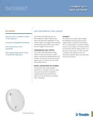
Figure 1-1 on page 9 shows the approximate radiobeacon coverage<br />
throughout the world. In this figure, light shaded regions note current<br />
coverage, with beacon stations symbolized as white circles.<br />
The world beacon networks continue to expand. For current coverage,<br />
consult the Hemisphere GPS web site at www.hemispheregps.com.<br />
8
<strong>MBX</strong>-4 <strong>User</strong> <strong>Guide</strong><br />
Figure 1-1. World DGPS Radiobeacon Coverage<br />
9
1: Introduction<br />
Factors Affecting Positioning Accuracy<br />
Many factors affect the positioning accuracy that a user may expect<br />
from a DGPS system. The most significant of these influences include:<br />
• Proximity of the remote user to the reference station<br />
• Age of the received differential corrections<br />
• Atmospheric conditions at the beacon and remote user<br />
locations<br />
• Satellite geometry, often expressed as a Dilution of Precision<br />
(DOP)<br />
• Magnitude of multipath present at the remote station<br />
• Quality of the GPS receiver being used at both the reference<br />
and remote stations.<br />
The distance between a remote user and the reference station is often<br />
considerable when using 300 kHz DGPS radiobeacons. Broadcast<br />
ranges may be as great as 450 km (280 miles) or more, depending<br />
primarily upon transmission power and surface conductivity.<br />
Consequently, some of the errors associated with GPS at the base<br />
station differ somewhat from those at the remote user’s location. This<br />
spatial decorrelation of errors can result in a relative position offset<br />
from the absolute coordinates of the remote receiver. This offset may<br />
be as much as one meter for every 100 km (62 miles) between the base<br />
station and remote receiver.<br />
10
<strong>MBX</strong>-4 <strong>User</strong> <strong>Guide</strong><br />
The latency of differential corrections also affects the achievable<br />
positioning accuracy at the remote receiver. Latency is a function of the<br />
following:<br />
• The time it takes the base station to calculate corrections<br />
• The data rate of the radio link<br />
• The time it takes the signal to reach the user<br />
• The time required for the remote differential receiver to<br />
demodulate the signal and communicate it to the GPS receiver.<br />
• Any data loss that occurs through reception problems<br />
Most of these delays require less than a second, though in some<br />
instances, depending upon the amount of information being<br />
transferred, overall delays of three to five seconds may occur. In the<br />
past when SA was “on,” latency was a concern if lock on the differential<br />
signal was lost for ten seconds or more. Without the effects of SA, the<br />
age of the differential corrections is not as significant, but care should<br />
be taken to ensure that their age is kept below a couple minutes by<br />
ensuring consistent beacon receiver lock.<br />
To account for latency, a GPS receiver can calculate approximate<br />
corrections until new corrections are available. Calculating the<br />
differential correction for a new epoch, using old corrections, leads to<br />
inaccuracy that grows with time. Accuracy is restored when new<br />
corrections become available.<br />
Although ionospheric errors are normally removed through differential<br />
positioning, the state of the ionosphere can differ between the base<br />
station and remote user over large distances. As the base station<br />
calculates corrections based on local ionospheric conditions, they may<br />
not completely account for the errors observed at the remote user’s<br />
location. This causes part of the spatial decorrelation that may be<br />
observed over large distances between base station and remote<br />
receivers<br />
11
1: Introduction<br />
The number of satellites visible and their geometry in the sky influences<br />
positioning accuracy. The Dilution of Precision (DOP) describes the<br />
strength of location and number of satellites in view of the receiver. A<br />
low DOP indicates a strong potential for better accuracy than a high<br />
DOP. Generally, more satellites visible to both the reference and remote<br />
receivers results in a lower DOP. Additionally, if the satellites are evenly<br />
spread around the receiver, rather than grouped in a few regions of the<br />
sky, a lower DOP (stronger solution) will result.<br />
Satellite signals received by the GPS receiver by a reflection from an<br />
object can decrease positioning accuracy. These multipath signals<br />
increase the measured range to a satellite as the signal takes a longer<br />
route to the GPS antenna. Certain precautions will minimize GPS<br />
antenna sensitivity to these reflected signals. Operating away from<br />
large reflective structures such as buildings or using special antennas<br />
and GPS equipment can help to reduce the impact of multipath. For<br />
most consumer-level applications, a small amount of multipath is<br />
tolerable.<br />
The quality of a GPS receiver has a dramatic influence on positioning<br />
accuracy. Consumer-based GPS products, such as many affordable<br />
handheld and fixed-mount receivers, typically operate with an accuracy<br />
of 2 to 5 meters horizontally 95% of the time. The accuracy of a<br />
particular product depends on the specific receiver’s performance<br />
characteristics. Higher accuracy GPS receivers are able to achieve up to<br />
1 meter of horizontal accuracy 95% of the time using real-time DGPS<br />
transmissions.<br />
12
<strong>MBX</strong>-4 <strong>User</strong> <strong>Guide</strong><br />
<strong>MBX</strong>-4 Beacon Receiver Information<br />
The <strong>MBX</strong>-4 receives, and demodulates RTCM SC-104 differential<br />
correction data transmitted by 300 kHz DGPS radiobeacons. The <strong>MBX</strong>-4<br />
house the Hemisphere GPS dual channel SBX-4 beacon receiver engine<br />
that features high-performance beacon search algorithms and a highly<br />
sensitive, adaptive architecture.<br />
The <strong>MBX</strong>-4 features:<br />
• Fast acquisition times ensuring that you are up and running<br />
quickly<br />
• Low power consumption giving extended battery life<br />
• Automatic and manual tune modes for versatility<br />
• Full NMEA 0183 command protocol for configuration,<br />
operation, and monitoring of receiver performance<br />
• Firmware upgrades uploaded through the serial port<br />
• Various baud rates for compatibility with “differential-ready”<br />
GPS products<br />
• A 2-line by 16-character display and 3-key control panel for<br />
operation of the receiver, and monitoring performance.<br />
• Built-in signal splitter allows output of GPS signal from<br />
combination GPS/beacon antenna to a separate GPS receiver<br />
13
1: Introduction<br />
MGL-4 Combined GPS / Magnetic Field Antenna<br />
The MGL-4 combines two individual antennas, an H-field Loop antenna<br />
and an L1 GPS patch antenna. Both of these elements are active and<br />
draw their power from the <strong>MBX</strong>-4 beacon receiver.<br />
14
2: Installation<br />
System Parts List<br />
Receiver Layout and Connections<br />
Installing the Receiver<br />
Installing the Antenna<br />
Internal Signal Splitter
2: Installation<br />
System Parts List<br />
The following list of standard equipment is included with the beacon<br />
receiver system:<br />
• <strong>MBX</strong>-4 Receiver<br />
• MGL-4 Antenna<br />
• Magnetic mount (threaded stem facilitates a 5/8” thread)<br />
• Reference Manual<br />
16
<strong>MBX</strong>-4 <strong>User</strong> <strong>Guide</strong><br />
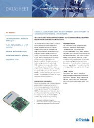
Receiver Layout and Connections<br />
The <strong>MBX</strong>-4 receiver is easily installed, requiring only power, data,<br />
antenna, and ground connections. Figure 1-1 illustrates the required<br />
receiver cable connections.<br />
Warning!<br />
The <strong>MBX</strong>-4 receiver provides 10 VDC across the antenna port labeled<br />
“ANT.” Connection to incompatible devices may result in damage to<br />
equipment. No voltage is provided on the GPS port and any voltage<br />
applied to this port from an external GPS product is DC-blocked for<br />
protection of the <strong>MBX</strong>-4.<br />
17
2: Installation<br />
Figure 2-1. Receiver Cable Interface<br />
18
<strong>MBX</strong>-4 <strong>User</strong> <strong>Guide</strong><br />
Installing the Receiver<br />
To ensure optimum receiver performance and ease of operation, you<br />
should consider the information presented in the following sections<br />
when installing the <strong>MBX</strong>-4 receiver.<br />
Receiver Placement<br />
When selecting a location to install the receiver, you should ensure that:<br />
• The receiver is within reach of power, data, and antenna cable<br />
connections.<br />
• Sufficient room is available at the back of the receiver to<br />
connect and disconnect the power, data, antenna, and ground<br />
cables if required.<br />
• Once you have installed the receiver, cables will not be bent or<br />
pinched as the receiver is tilted up or down.<br />
• You have a clear view and access to the receiver’s front panel,<br />
to monitor the receiver status, if you require<br />
Environmental Considerations<br />
The <strong>MBX</strong>-4 is designed to operate within enclosed environments where<br />
the temperature remains between -22° F and 158° F (-30° C and +70° C<br />
and relative humidity is less than 95 percent. It may be stored between<br />
-40° F and +176° F (-40° C and +80° C).<br />
19
2: Installation<br />
Power Considerations<br />
The <strong>MBX</strong>-4 possesses a 2-conductor, positive locking, circular power<br />
connector and operate with an input voltage between 9 and 40 VDC. For<br />
best performance, the supplied power should be continuous and clean.<br />
You may use an in-line power filter to minimize power fluctuations<br />
resulting from additional electrical accessories connected to the same<br />
power supply.<br />
The backlit LCD display of the <strong>MBX</strong>-4 receiver remains illuminated while<br />
power is applied.<br />
Table 2-1 Power Requirements of the <strong>MBX</strong>-4.<br />
Table 2-1: Power requirements<br />
Receiver Input voltage Input current Input power<br />
<strong>MBX</strong>-4 9-40 Vdc 210 mA @ 12 VDC 2.5 W<br />
To power the receiver:<br />
1. Connect the red wire of the supplied power cable to DC positive (+).<br />
2. Connect the black wire of the supplied power cable to DC<br />
negative (-).<br />
3. Connect the keyed, two-conductor socket connector of the power<br />
cable to the receiver’s power input connector, labeled PWR.<br />
Both receivers possess reverse polarity protection to prevent damage if<br />
the power leads are reversed.<br />
A 1.5 A slow blow fuse, situated in-line of the power cable protects the<br />
receiver from power surges. The fuse container should remain<br />
accessible after installation.<br />
20
<strong>MBX</strong>-4 <strong>User</strong> <strong>Guide</strong><br />
Warning!<br />
Do not operate the <strong>MBX</strong>-4 with the 1.5 A fuse bypassed. Such<br />
modification will void the product warranty.<br />
Grounding the Receiver<br />
For best performance, connect the ground screw, labelled GND, on the<br />
back of the <strong>MBX</strong>-4 to a counterpoise (artificial) ground. This ground<br />
point may be a ground plate on a marine vessel, the chassis of a<br />
vehicle. Other grounds may provide acceptable performance. You<br />
should minimize the overall length of the ground wires for best<br />
performance, if possible.<br />
Connecting the Receiver To External Devices<br />
Both receivers support RS-232C (default) and RS-422 interface levels for<br />
communication with differentially capable GPS products. They feature<br />
one external bi-directional data port used for transmitting RTCM SC-104<br />
differential correction data to a GPS receiver, and for remote control<br />
and querying of the beacon receiver using a terminal device. This data<br />
port is located at the back panel of the receiver and is a DB9 socket<br />
connector.<br />
21
2: Installation<br />
Table 2-2 provides pin-assignment information for the data port of the<br />
receiver, at the default RS-232 interface level. Table 2-3 provides the<br />
pin-assignments for the data port at the RS-422 level.<br />
Table 2-2: Receiver data pin-out, RS-232 interface level<br />
Pin number Signal Description<br />
2 Transmit RTCM SC-104/status output<br />
3 Receive NMEA Input<br />
5 Signal ground Signal return<br />
Table 2-3: Receiver data Pin-out, RS 422 interface level<br />
Pin number Signal Description<br />
1 Transmit + RTCM SC-104/status output +<br />
2 Transmit - RTCM SC-104/status output -<br />
4 Receive NMEA input -<br />
5 Signal ground Signal return<br />
7 Receive + NMEA input +<br />
To establish communications between the beacon receiver and your<br />
GPS, you must connect the transmit pin(s) of the beacon receiver to the<br />
receive pin(s) of the GPS receiver.<br />
Optionally, you may connect the receive pin(s) of the beacon receiver to<br />
the GPS, or communicating device transmit line. This is required for<br />
display of GPS information on the <strong>MBX</strong>-4 LCD display when in BX-E<br />
mode, and for tuning of the <strong>MBX</strong>-4 receiver remotely. You must connect<br />
the signal ground (pin 5) of the beacon receiver to the signal ground of<br />
the external GPS device.<br />
22
<strong>MBX</strong>-4 <strong>User</strong> <strong>Guide</strong><br />
Figure 2-2 illustrates this requirement for a GPS receiver operating at<br />
the RS-232 communications level:<br />
<strong>MBX</strong>-3S<br />
GPS<br />
Pin 2 - Tx<br />
Rx<br />
Pin 5 - Gnd<br />
Signal Ground<br />
Gnd<br />
Pin 3 - Rx<br />
Tx<br />
Figure 2-2. Receiver I/O Interface, RS-232<br />
Figure 2-3 illustrates this requirement for a GPS receiver operating at<br />
the RS-422 communications level:<br />
<strong>MBX</strong>-3S<br />
Pin 1 - Tx +<br />
Rx +<br />
GPS<br />
Pin 7 - Rx + Tx +<br />
Pin 5 - Gnd Signal Ground Gnd<br />
Pin 2 - Tx -<br />
Rx -<br />
Pin 4 - Rx - Tx -<br />
Figure 2-3. Receiver I/O Interface, RS-422<br />
For successful communications, the baud rate of the beacon receiver<br />
must be set to match that of the GPS receiver. Refer to the “Change<br />
Baud Rate” section on page 51 for instructions set the <strong>MBX</strong>-4 baud rate<br />
using the display and keypad, and the “<strong>MBX</strong>-4 Port Rate Command<br />
($PCSI,6)” section on page 63 for information to change the baud rate<br />
using proprietary NMEA commands.<br />
23
2: Installation<br />
RS-232 and RS-422 Operation<br />
A majority of GPS receiver products communicates at the RS-232 level,<br />
similar to a PC computer. However, there are a number of chart-plotting<br />
devices, incorporating GPS capabilities, that operating at the RS-422<br />
interface level. The default communication level of the <strong>MBX</strong>-4 is RS-232.<br />
To switch from the default RS-232 communication level, you must<br />
remove the <strong>MBX</strong>-4’s front and back panels to slide the receiver board<br />
out of the case approximately 2 inches (5 centimeters). Always observe<br />
proper electrostatic discharge precautions (ESD) when handling the<br />
beacon receiver or its components, outside of the enclosure. Such<br />
precautions include proper grounding of personnel, tools, and the<br />
surface upon which the receiver rests.<br />
You will require a Philip’s screwdriver to open the front and back panels<br />
of the <strong>MBX</strong>-4. Once you have removed the front panel screws for the<br />
<strong>MBX</strong>-4, carefully remove the front plate and disconnect the ribbon<br />
cables of the display and keypad, taking note of connector orientation<br />
when secured. Do not pull on the ribbon cables, hold onto the<br />
connector when removing so that strain is not placed on the cable.<br />
When making this modification, do not draw the printed circuit board<br />
fully out of the enclosure. Instead, slide the board out no more than two<br />
inches before reaching in to reposition the RS-232/RS-422 slide switch.<br />
Use of a ball-point pen is recommended when making this adjustment.<br />
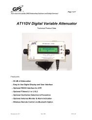
Figure 2-4 illustrates the location of the RS-232/RS-422 slide switch<br />
within the receiver:<br />
24
<strong>MBX</strong>-4 <strong>User</strong> <strong>Guide</strong><br />
1S<br />
RS-422<br />
RS-232<br />
Figure 2-4. RS-232/RS-422 Configuration<br />
With the switch set to the lower position (as viewed in Figure 2-4), the<br />
receiver communicates at the RS-232 level. When set to the upper<br />
position, the receiver communicates at the RS-422 level. The interface<br />
level corresponding to the switch position is silk-screened onto the<br />
circuit board for identification.<br />
Warning!<br />
The <strong>MBX</strong>-4 is an electrostatic sensitive device. Observe proper<br />
precautions when handling the receivers during this procedure.<br />
Damage caused to the receiver by ESD is not covered under<br />
warranty.<br />
Once you have set the slide switch to the desired position, slide the<br />
receiver board back into the enclosure. Reconnect the front panel<br />
display and keypad ribbon cables. When replacing the front and back<br />
plate screws ensure that no cables or components catch between the<br />
panels and the housing.<br />
25
2: Installation<br />
Installing the Antenna<br />
The following sections provide antenna installation details and<br />
discusses the internal signal splitter.<br />
Antenna Placement to Optimize Reception<br />
Local noise generated by your vehicle, vessel, or surroundings may<br />
affect your beacon system performance. To minimize this impact, you<br />
should locate the antenna outside the path of a radar beam, away from<br />
any transmitting antennas, and away from any other source of<br />
interference such as motors, solenoids, and other electronics.<br />
Your receiver calculates a Signal to Noise Ratio (SNR), measured in dB<br />
(Decibels) which indicates the receiver’s performance. The SNR is<br />
height of the signal above the noise floor. The higher the SNR, the<br />
better your receiver is receiving the signal. The optimum antenna<br />
location will be a position where your average SNR is highest. You<br />
should turn on all accessories that you intend to use during normal<br />
operation when locating the best position for the antenna.<br />
The <strong>MBX</strong>-4 receiver displays the SNR within the Beacon Status menu.<br />
You may alternatively issue a NMEA query to the receiver through the<br />
serial port to get this information. Normally you will require a PC<br />
computer with a terminal program to do this, however, some GPS<br />
systems will display the SNR, such as Garmin GPS receivers (you must<br />
connect the GPS transmit signal to the receive of the beacon receiver).<br />
Hemisphere GPS offers free PC computer controller software for<br />
interfacing with Hemisphere GPS beacon receiver equipment, located<br />
on the Hemisphere GPS web site at: www.hemispheregps.com,<br />
however, this is not normally needed for operation of the <strong>MBX</strong>-4.<br />
26
<strong>MBX</strong>-4 <strong>User</strong> <strong>Guide</strong><br />
MGL-4 Combined GPS/Beacon Antenna<br />
Install the MGL-4 combined GPS/beacon antenna in a location with a<br />
clear, unobstructed view of the sky.<br />
The MGL-4 uses a 1-14-UNS thread for mounting. A magnetic mount<br />
with integral 5/8 th inch threaded shaft is provided with the <strong>MBX</strong>-4. For<br />
best performance, mount this antenna so that the center of the black<br />
gasket is at least 3 inches (8 centimeters) above any ferrous material.<br />
Note: Mount this antenna with a clear, unobstructed view of the<br />
sky and 3 inches (8 centimeters) away from any metal surface.<br />
Warning!<br />
Antennas threaded onto a mount should be tightened only by<br />
hand. Do not use tools to install the MGL-4 as this may cause<br />
damage to the antenna. Damage caused by over tightening is<br />
not covered under warranty.<br />
Routing and Securing the Antenna Cable<br />
Hemisphere GPS beacon antennas require a 50 omega impendance<br />
antenna extension cable such as RG-58U (up to a maximum of 492 feet<br />
(150 meters) in length) for proper operation. in the case of the combined<br />
MGL-4, cable losses at the higher GPS frequency (1.575 GHz) restrict the<br />
cable length to approximately 32.8 feet (10 meters) (for RG-58U cable),<br />
depending on GPS receiver requirements. For more information on<br />
cable length, please contact your Hemisphere GPS dealer or<br />
Hemisphere GPS technical support.<br />
27
2: Installation<br />
When choosing a route for the antenna extension cable, consider the<br />
following recommendations:<br />
• Avoid running cables in areas of excessive heat.<br />
• Keep antenna cables away from corrosive chemicals.<br />
• Do not run the extension cable through door or window jams.<br />
• Keep the antenna cable away from rotating machinery.<br />
• Do not bend or crimp the antenna extension cable.<br />
• Avoid placing tension on the cable.<br />
• Remove unwanted slack from the antenna extension cable at<br />
the receiver end.<br />
• Secure along the cable route using plastic tie wraps.<br />
Warning!<br />
The <strong>MBX</strong>-4 receiver provides 10 VDC across the antenna port.<br />
Connection to incompatible devices may result in damage to<br />
equipment. No voltage is provided on the GPS port and any<br />
voltage applied to this port from an external GPS product is DCblocked<br />
for protection of the <strong>MBX</strong>-4.<br />
Warning!<br />
Connect the antenna to the beacon receiver before you apply<br />
power to the receiver.<br />
Warning!<br />
Improperly installed cables near machinery can be dangerous.<br />
28
<strong>MBX</strong>-4 <strong>User</strong> <strong>Guide</strong><br />
Magnetic Mount<br />
The magnetic mount, can be used to install the MGL-4 antennas on any<br />
ferrous surface such as the roof of a vehicle. It consists of a mounting<br />
extension three inches long, attached to a circular metal disk, housing a<br />
magnet. A Mylar cover on the bottom of the mount protects the<br />
mounting surface from abrasion. (Hemisphere GPS part number.<br />
A three inch diameter zinc plated steel disc and a double sided adhesive<br />
foam pad are included with the magnetic mount to attach the magnetic<br />
mount to non-ferrous surfaces, such as fiberglass rooftops. For such an<br />
installation, remove the protective backing from both sides of the<br />
adhesive foam pad, and affix the foam pad to the non-ferrous surface.<br />
Place the disc on top of the foam pad. You can then place the magnetic<br />
mount securely on the metal plate, and remove as necessary.<br />
The stem of the magnetic mount is removable from the base and<br />
facilitates a 5/8” thread commonly used in the GIS and mapping<br />
industry.<br />
29
2: Installation<br />
Internal Signal Splitter<br />
The <strong>MBX</strong>-4 receivers feature an internal signal splitter for use with the<br />
MGL-4 antenna. The Internal Signal Splitter separates the GPS and<br />
beacon signals. The beacon portion of the combined signal is supplied<br />
to the internal beacon receiver, while the GPS signal is re-directed out<br />
of the receiver through the TNC-S coaxial connector labeled GPS (see<br />
Figure 2-6). This feature eliminates the need for a separate GPS antenna<br />
or an external splitter box, reducing the amount of cable required for an<br />
installation. No voltage is provided through this port and any voltage<br />
applied to this port from an external GPS product is DC-blocked for<br />
protection of the <strong>MBX</strong>-4.<br />
30
<strong>MBX</strong>-4 <strong>User</strong> <strong>Guide</strong><br />
Figure 2-5. <strong>MBX</strong>-4 Internal Signal Splitter Interface<br />
31
2: Installation<br />
32
3: <strong>MBX</strong>-4 Configuration and<br />
Operation<br />
Front Display and Keypad<br />
Factory Default Settings<br />
Tune Modes<br />
Display Modes<br />
<strong>MBX</strong>-4 Menu Systems<br />
<strong>MBX</strong>-4 Receiver Performance - SNR Reading<br />
Operation of <strong>MBX</strong>-4 with Garmin GPS<br />
Configuring the Receiver
3: <strong>MBX</strong>-4 Configuration and Operation<br />
Front Display and Keypad<br />
The <strong>MBX</strong>-4 features a 2-line by 16-character LCD and 3-key control<br />
panel. The control panel is composed of an up arrow , enter , and<br />
down arrow key. These keys allow you to navigate through the<br />
intuitive <strong>MBX</strong>-4 menu system, configuring operating parameters and<br />
viewing status information. Figure 3-1 shows the display and keypad of<br />
the <strong>MBX</strong>-4. The top line of the display is the active Focus Line for<br />
keypad operations.<br />
Figure 3-1. <strong>MBX</strong>-4 Display and Keypad<br />
Note - The top line of the <strong>MBX</strong>-4 display is the Focus Line,<br />
denoted by the left and right arrows on either side of the<br />
display. The field of interest must be “in focus” for<br />
keystrokes to have the desired effect.<br />
34
<strong>MBX</strong>-4 <strong>User</strong> <strong>Guide</strong><br />
Lock Status<br />
The <strong>MBX</strong>-4 indicates lock status in the upper right hand corner of the<br />
display. The lock symbol, illustrated in Figure 3-2, remains in the closed<br />
position when the <strong>MBX</strong>-4 is locked to an RTCM signal, and open, when<br />
no broadcast is available for the specified frequency and/or MSK bit<br />
rate.<br />
Lock<br />
No Lock<br />
Figure 3-2. <strong>MBX</strong>-4 Beacon Lock Indicator<br />
35
3: <strong>MBX</strong>-4 Configuration and Operation<br />
Factory Default Settings<br />
Table 3-1 presents the factory default <strong>MBX</strong>-4 operation settings, while<br />
Table 3-2 lists the default communication settings. These operation and<br />
port settings are valid upon initial power-up. The <strong>MBX</strong>-4 maintains any<br />
changes made to its operation or port settings for subsequent powerup.<br />
Note: The changes you make to the <strong>MBX</strong>-4 configuration are saved<br />
in memory for subsequent power-up.<br />
Table 3-1: Default <strong>MBX</strong>-4 Operating Settings<br />
Tune Mode<br />
Automatic<br />
Display Mode<br />
<strong>MBX</strong>-4<br />
Table 3-2: Default <strong>MBX</strong>-4 Port Settings<br />
Baud Rate<br />
Data<br />
Bits<br />
Parity<br />
Stop Bit<br />
Interface<br />
Level<br />
P1-Main: 4800 8 None 1 RS-232C<br />
36
<strong>MBX</strong>-4 <strong>User</strong> <strong>Guide</strong><br />
Tune Modes<br />
The <strong>MBX</strong>-4 may be operated in either Automatic or Manual Tune Mode.<br />
In Automatic Beacon Search (ABS) Mode, the receiver identifies and<br />
tunes to the station providing the strongest DGPS signal. In Manual<br />
Mode, you specify the frequency to which the receiver will tune.<br />
Refer to Figure 3-4 on page 37, and the “Configuring the Receiver”<br />
section on page 51 to switch between Automatic and Manual Tune<br />
modes using the display and keypad.<br />
Automatic Beacon Search (ABS) Mode<br />
The <strong>MBX</strong>-4 receiver operates in Automatic Beacon Search (ABS) mode<br />
by default, selecting and tuning to the most appropriate beacon without<br />
operator intervention. The <strong>MBX</strong>-4 uses its two independent channels to<br />
identify and lock to DGPS beacons without interrupting the continuous<br />
flow of RTCM data to your GPS receiver.<br />
ABS mode is ideal for navigation applications over considerable areas,<br />
eliminating the need for operator intervention when travelling from one<br />
beacon coverage zone to another.<br />
Global Search - When powered for the first time in ABS mode, the<br />
<strong>MBX</strong>-4 initiates a Global Search, examining each available DGPS<br />
beacon frequency, and recording Signal Strength (SS) measurements in<br />
units of dBmV/m to the Global Search Table. The receiver uses these<br />
measured values to compute an average SS, and noise floor, and to sort<br />
the frequencies in descending order of SS. The two channels<br />
cooperatively examine the frequencies with the highest SS<br />
measurements, above the computed noise floor, to determine the<br />
station providing the strongest RTCM signal. The receiver's primary<br />
channel locks to the first identified DGPS broadcast, while the second<br />
channel continues searching in the background for superior beacon<br />
signals. If no signal is available, the <strong>MBX</strong>-4 will initiate a fresh Global<br />
Search, continuing this cycle until it finds a valid beacon.<br />
37
3: <strong>MBX</strong>-4 Configuration and Operation<br />
Background Search - During the Background Search, the second<br />
channel examines all frequencies at both the 100 and 200 bps MSK bit<br />
rates to identify beacons possessing superior signal quality. If a DGPS<br />
broadcast is identified that exhibits a 2 dB greater signal strength than<br />
that of the primary station, the receiver will automatically switch to this<br />
beacon. No loss of lock occurs on the primary station during the<br />
background scan.<br />
The <strong>MBX</strong>-4 stores the current primary beacon in memory so that it is<br />
available upon subsequent power-up. You may force a new Global<br />
Search at any time using the proprietary NMEA 0183 command defined<br />
in Chapter 5.<br />
Manual Mode<br />
In Manual tune mode, you may select a specific frequency and bit rate<br />
for the receiver to tune to, or simply specify the frequency, allowing the<br />
<strong>MBX</strong>-4 to identify the correct MSK bit rate on its own. This mode of<br />
operation is most useful when working in an area where you know the<br />
frequency though not necessarily the MSK bit rate of the closest<br />
beacon.<br />
The <strong>MBX</strong>-4 also provides the capability to select a beacon by name<br />
from the World Beacon Table stored within receiver memory. You can<br />
update this table via the <strong>MBX</strong>-4 serial port, as detailed in Chapter 4.<br />
38
<strong>MBX</strong>-4 <strong>User</strong> <strong>Guide</strong><br />
<strong>MBX</strong>-4 Display Modes<br />
The <strong>MBX</strong>-4 operates in one of two modes as described in the following<br />
sections.<br />
BX Mode<br />
This is the default mode of receiver operation. In <strong>MBX</strong>-4 mode, you<br />
have display and keypad access to all information related to beacon<br />
receiver operation and configuration. The receiver outputs RTCM data<br />
through the transmit data line of the serial port, and receives<br />
configuration commands and status queries through the data port<br />
receive pin.<br />
BX-E Mode<br />
In BX-E, or external GPS input mode, standard NMEA 0183 GPS<br />
messages ($GPGGA, $GPVTG, $GPZDA, and $GPGSV) are input from<br />
an external GPS receiver, and the position, navigation, and satellite<br />
information contained within these messages is displayed by the<br />
<strong>MBX</strong>-4. The <strong>MBX</strong>-4 continues to output RTCM data to the external GPS<br />
device while in this mode. This feature can be very useful when working<br />
with a GPS receiver that does not provide a graphical interface.<br />
You may select BX mode from the Options section of the Setup menu,<br />
as described in this chapter. Refer to Chapter 2 to connect an external<br />
GPS receiver for BX-E operations. Please consult your GPS receiver<br />
user’s guide for more information on these GPS NMEA messages.<br />
39
3: <strong>MBX</strong>-4 Configuration and Operation<br />
Position Fix Status (BX Mode Only) - When configured for BX<br />
mode, the <strong>MBX</strong>-4 provides an indication of the GPS lock status, as<br />
contained within the $GPGGA message string input from the external<br />
GPS receiver. This indicator is located in the lower right hand corner of<br />
the <strong>MBX</strong>-4 display. Figure 3-3, describes the three states of GPS lock.<br />
No Fix GPS DGPS<br />
Figure 3-3. BX-E Position Fix Indicator<br />
In the first state, the two parallel vertical lines indicate that no position<br />
fix is available. The second state, denoted by the hollow circle between<br />
the two parallel vertical lines states that the receiver is tracking four<br />
satellites or more, and is computing a position. This indicator is a<br />
symbol representing a GPS satellite. The third state, denoted by the<br />
solid circle between the two parallel vertical lines indicates that the GPS<br />
receiver is computing differentially corrected position solutions.<br />
40
<strong>MBX</strong>-4 <strong>User</strong> <strong>Guide</strong><br />
<strong>MBX</strong>-4 Menu System<br />
Figure 3-4 illustrates the <strong>MBX</strong>-4 display and keypad actuated menu<br />
system.<br />
Position Status<br />
Lat<br />
Lon<br />
Hgt<br />
Hdg<br />
Vel<br />
Legend<br />
Enter Key<br />
Down Arrow<br />
Up Arrow<br />
UTC<br />
Age<br />
Short Cut<br />
<strong>User</strong> Entry<br />
SV Count<br />
HDOP<br />
Back<br />
Satellites<br />
Ch01-SV00 El00<br />
Az 000 SNR 00<br />
Ch12-SV00 El00<br />
Az 000 SNR 00<br />
Back<br />
BX-E Mode<br />
BX Mode<br />
Start-Up<br />
Sequence<br />
Beacon Status<br />
Stn 305.0 B200<br />
SS 000 SNR 000<br />
PRF 100% Q25<br />
Unselected Bx<br />
ID 00000 H 0<br />
Back<br />
Setup<br />
Options<br />
Baud Rt 4800<br />
Auto Bx Search<br />
XBX3 Mode:<br />
Tune 305.0/200<br />
L/L Units<br />
Select Beacon<br />
Continent<br />
...<br />
Country<br />
...<br />
Beacon Name<br />
...<br />
Hgt Unit Meters<br />
Subscription<br />
Back<br />
Back<br />
Back<br />
Vel Unit KPH<br />
Version Display<br />
UTC Offset<br />
Back<br />
Back<br />
Figure 3-4. <strong>MBX</strong>-4 Menu System<br />
41
3: <strong>MBX</strong>-4 Configuration and Operation<br />
Start-Up Sequence<br />
When power is applied, the <strong>MBX</strong>-4 will sequence through four<br />
initialization screens. These start up screens include a receiver<br />
initialization and memory check, a display test, a splash screen, and a<br />
screen displaying the receiver serial number, software version, and the<br />
current display mode.<br />
Following initialization, the receiver proceeds directly to the Beacon<br />
Status branch of the menu tree. When operating in BX mode, the BX<br />
will proceed directly to the Position Status branch of the menu tree.<br />
Beacon Status<br />
The Beacon Status section of the menu tree provides access to<br />
information related to the status of the receiver's primary channel.<br />
1 S t n 3 0 5 . 0 B 2 0 0 ¨ Focus Line<br />
2 S S 0 3 1 S N R 0 1 5<br />
3 M T P 1 0 0 Q 2 5<br />
4 U n s e l e c t e d B X<br />
5 I D 0 0 0 0 0 H 1<br />
6 B a c k<br />
Stn<br />
Frequency in kHz to which the <strong>MBX</strong>-4 is tuned.<br />
B<br />
MSK bit rate in bits per second (bps) at which the <strong>MBX</strong>-4 is<br />
demodulating data.<br />
SS<br />
Signal Strength in dBmV/m - a SS of 20 is 10 mV/m<br />
42
<strong>MBX</strong>-4 <strong>User</strong> <strong>Guide</strong><br />
SNR<br />
Ratio of SS over computed noise floor in dB, refer to Chapter 3 for<br />
information<br />
MTP<br />
Message throughput (correct data ³ total data x 100%)<br />
Q<br />
Number of consecutive 30 bit RTCM words received correctly (max Q<br />
count = 25).<br />
Unselected<br />
BX<br />
Name of the beacon to which the receiver is tuned. This field is only<br />
updated if a specific beacon is selected from the receiver's Global<br />
Beacon Table.<br />
ID<br />
Reference station identifier as contained within the RTCM broadcast<br />
messages.<br />
H<br />
Health of the transmitting beacon. Table 3-3 defines the various health<br />
values.<br />
Table 3-3: Beacon Health Status Values<br />
Health Code Indication<br />
0 – 5 Reference Station Transmission Broadcast -<br />
Monitored<br />
6 Reference Station Transmission Broadcast –<br />
Un-monitored<br />
7 Reference Station Not Working<br />
43
3: <strong>MBX</strong>-4 Configuration and Operation<br />
Top Menu<br />
Returns the receiver to the top menu level.<br />
Black<br />
Returns the receiver to the last viewed menu.<br />
Setup<br />
The Setup section of the menu tree provides access to <strong>MBX</strong>-4<br />
configuration information and sub-menus.<br />
1 O p t i o n s ¨ Focus Line<br />
2 A u t o B X S e a r c h<br />
3 T u n e 3 2 5 . 0 / 2 0 0<br />
4 S e l e c t B e a c o n<br />
5 S u b s c r i p t i o n<br />
6 V e r s i o n D i s p l a y<br />
7 B a c k<br />
The Options sub-menu provides access to the following configuration<br />
parameters:<br />
1 B a u d R t 4 8 0 0 ¨ Focus Line<br />
2 X B X 3 M o d e : B X<br />
3 L / L U n i t D M . M<br />
4 H g t U n i t M e t e r s<br />
5 V e l U n i t K P H<br />
6 U T C O f f s e t 0<br />
7 B a c k<br />
44
<strong>MBX</strong>-4 <strong>User</strong> <strong>Guide</strong><br />
Baud Rate<br />
P1-MAIN {2400, 4800, 9600 bd}<br />
Baud rate at which the <strong>MBX</strong>-4 communicates through the bi-directional<br />
DB-9S data connector (Pins 2 and 3). Change this parameter to match<br />
the baud rate of the external GPS device with which the <strong>MBX</strong>-4 is<br />
communicating.<br />
XBX3 Mode<br />
{BX, BX-E, GBX, GBX-E, GLX}<br />
BXDefault mode of operation. In BX-3 mode, the <strong>MBX</strong>-4 receiver<br />
accepts command and query messages, and outputs RTCM and NMEA<br />
status messages through its external communications port.<br />
BX-EMode of operation in which the <strong>MBX</strong>-4 will display GPS position,<br />
navigation, and satellite data as input from an external GPS device.<br />
(GGA, VTG, ZDA, GSV NMEA message input required)<br />
GBXNot applicable (only used with GBX Series combination Beacon/<br />
GPS receivers). Do not configure the <strong>MBX</strong>-4 for this mode of operation.<br />
GBX-ENot applicable (only used with GBX Series combination Beacon/<br />
GPS receivers). Do not configure the <strong>MBX</strong>-4 for this mode of operation.<br />
GLXMode of operation reserved for Hemisphere GPS LGBX products<br />
incorporating GPS, Beacon, and OmniSTAR L-Band receiver<br />
technologies. Do not configure the <strong>MBX</strong>-4 for this mode of operation.<br />
L/L Unit<br />
{DM.M, DMS, DD}<br />
Pressing with this line in focus allows you set the units of the Lat and<br />
Lon parameter displayed in the Position Status section of the menu.<br />
45
3: <strong>MBX</strong>-4 Configuration and Operation<br />
Use the and keys to select the desired units, and press again<br />
to implement the change.<br />
Hgt Unit<br />
{Meters, Feet}<br />
Pressing with this line in focus allows you set the units of the Hgt<br />
parameter displayed in the Position Status section of the menu, in BX-E<br />
mode. Use the and keys to select the desired units, and press<br />
again to implement the change.<br />
Vel Unit<br />
{KPH, MPH, k}<br />
Pressing with this line in focus allows you set the units of the Vel<br />
parameter displayed in the Position Status section of the menu, in BX-E<br />
mode. Use the and keys to select the desired units (kilometers/<br />
hour, miles/hour, or knots), and press again to implement the<br />
change.<br />
UTC Offset<br />
{-12 to +12 hours}<br />
Pressing with this line in focus allows you set the local time offset<br />
from UTC allowing the display of local time, in the Position Status<br />
section of the menu, in BX-E mode. Use the and keys to select<br />
the desired offset in hours, and press again to implement the<br />
change.<br />
Back<br />
Returns the <strong>MBX</strong>-4 to the Setup menu level.<br />
46
<strong>MBX</strong>-4 <strong>User</strong> <strong>Guide</strong><br />
The Setup menu also provides the following configuration and<br />
information options.<br />
Auto Bx Search<br />
Pressing with this line in focus sets the <strong>MBX</strong>-4 to ABS mode, erasing<br />
the stored Global Search Table and forcing a new Global Search.<br />
Tune 325.0/200<br />
Pressing<br />
with this line in focus allows you set the beacon frequency<br />
and MSK rate to which the receiver should tune. The and keys<br />
increment the frequency by 500 Hz, with three MSK rate options, 100<br />
bps, 200 bps, and Auto, available for each increment. Select Auto if you<br />
know the frequency of the beacon but are uncertain of the correct MSK<br />
rate. When the correct frequency and bit rate is displayed, press<br />
proceed to the Beacon Status menu.<br />
Select Beacon<br />
This feature allows you to select a particular beacon for a geographical<br />
region. Geographic regions are resolved into continent and country.<br />
Upon selecting a beacon, the <strong>MBX</strong>-4 will automatically return to the<br />
Beacon Status menu, updating the Stn/B and beacon name fields.<br />
Subscription<br />
The subscription feature allows you to configure the <strong>MBX</strong>-4 for<br />
operation within a Hemisphere GPS proprietary encrypted RTCM<br />
broadcast network. To enable this feature, please contact your<br />
Hemisphere GPS dealer or Hemisphere GPS Customer Service.<br />
Version Display<br />
Displays the <strong>MBX</strong>-4 serial number, resident firmware, SBX-4-2<br />
firmware, and receiver diagnostic checksums.<br />
to<br />
47
3: <strong>MBX</strong>-4 Configuration and Operation<br />
Back<br />
Returns the <strong>MBX</strong>-4 to the top menu level.<br />
Position Status (BX-E Mode Only)<br />
The Position Status section of the menu tree provides access to BX-E<br />
GPS position and navigation status information provided by an external<br />
GPS sensor outputting the associated NMEA 0183 GPS message<br />
strings.<br />
1 L a t 5 1 4 6 . 2 3 4 N ¨ Focus Line<br />
2 L o n 1 1 4 0 3 . 1 4 3 W<br />
3 H g t 1 0 3 9 . 0 M<br />
4 H d g 1 9 . 7 o t r u e<br />
5 V e l 2 4 . 4 K<br />
6 U T C 1 1 : 4 7 : 3 6<br />
7 A g e 7 . 0 s<br />
8 S V C o u n t 0 9<br />
9 H D O P 1 . 9<br />
1 B a c k<br />
Lat<br />
Displays the current latitude in degrees, minutes, decimal minutes<br />
(DM.M) as input from an external GPS receiver. This information is<br />
parsed from the NMEA $GPGGA message string.<br />
Lon<br />
Displays the current longitude in degrees, minutes, decimal minutes<br />
(DM.M) as input from an external GPS receiver. This information is<br />
parsed from the NMEA $GPGGA message string.<br />
48
<strong>MBX</strong>-4 <strong>User</strong> <strong>Guide</strong><br />
Hgt<br />
Displays the current height in either meters or feet depending on the<br />
units selected, as input from an external GPS receiver (See Chapter 4).<br />
This information is parsed from the NMEA $GPGGA message string.<br />
Hdg<br />
Displays the horizontal heading clockwise from True North in degrees.<br />
This information is parsed from the NMEA $GPVTG message string.<br />
Vel<br />
Displays the horizontal speed in KPH, MPS, or knots depending on the<br />
units selected, as input from an external GPS receiver (See Chapter 4).<br />
This information is parsed from the NMEA $GPVTG message string.<br />
UTC<br />
Displays the current UTC Time with local offset as input from an<br />
external GPS receiver (See Chapter 4). This information is parsed from<br />
the NMEA $GPZDA message string.<br />
Age<br />
Displays the current DGPS age of correction in seconds, as input from<br />
an external GPS receiver. This information is parsed from the NMEA<br />
$GPGGA message string.<br />
SV Count<br />
Displays the current number of satellites being used by the GPS<br />
receiver in computing its position. If this value is 4 or greater, then the<br />
computed position is 3D, and includes a valid height solution. If less<br />
than four, then the solution is 2D, holding the height parameter<br />
constant at either 0, or its last measured value.<br />
49
3: <strong>MBX</strong>-4 Configuration and Operation<br />
HDOP<br />
Displays the Horizontal Dilution of Precision (HDOP). This information is<br />
parsed from the NMEA $GPGGA message string.<br />
Back<br />
Returns the <strong>MBX</strong>-4 to the top menu level.<br />
Satellites (BX-E Mode Only)<br />
The Satellites section of the menu tree provides access to BX-E GPS<br />
satellite information provided by an external GPS sensor. Pressing the<br />
and keys allows you to scroll through the available GPS receiver<br />
channels, numbered Ch01 through Ch12.<br />
1 C h 0 1 - S V 1 5 E L 0 9 ¨ Focus Line<br />
2 A z 1 5 4 S N R 4 1<br />
3 B a c k<br />
Ch01<br />
Displays the external GPS receiver channel (01-12) for which the<br />
satellite information provided is valid. This information is parsed from<br />
the NMEA $GPGSV or $PASHS,SAT message strings.<br />
SV12<br />
Displays the GPS satellite SV number tracked by channel “XX” of the<br />
external GPS receiver. This information is parsed from the NMEA<br />
$GPGSV or $PASHS,SAT message strings.<br />
El<br />
Displays the elevation angle (0× - horizon to 90×- vertical) of the SV<br />
relative to the external GPS receiver antenna. This information is parsed<br />
from the NMEA $GPGSV or $PASHS,SAT message strings.<br />
50
<strong>MBX</strong>-4 <strong>User</strong> <strong>Guide</strong><br />
Az<br />
Displays the azimuth angle (0× = 360× = North) of the SV relative to the<br />
external GPS receiver antenna. This information is parsed from the<br />
NMEA $GPGSV or $PASHS,SAT message strings.<br />
SNR<br />
Displays the signal to noise ratio of the satellite signal measured by the<br />
external GPS receiver. This information is parsed from the NMEA<br />
$GPGSV or $PASHS,SAT message strings.<br />
Back<br />
Returns the <strong>MBX</strong>-4 to the top menu level.<br />
Menu System Shortcuts<br />
There are a number of shortcuts present within the <strong>MBX</strong>-4’s menu<br />
system that may allow you to navigate through it more efficiently. A<br />
shortcut allows you to move from one menu directly to separate menu<br />
without having to choose the Back menu item.<br />
When Stn/B of the Beacon Status menu is in focus, you may press<br />
to proceed directly to the Tune command line of the Setup menu. You<br />
may then press again to change the frequency and bit rate to which<br />
the receiver is tuned using the and keys. When the correct<br />
frequency and bit rate are displayed, press a third time to tune the<br />
receiver and return to the Beacon Status menu.<br />
When Unselected BX of the Beacon Status menu, is in focus, you may<br />
press<br />
to proceed directly to the Select Beacon menu item of the<br />
Setup menu. You may then press again to select a specific beacon<br />
by geographic region by name using the , and keys. When the<br />
51
3: <strong>MBX</strong>-4 Configuration and Operation<br />
correct beacon name is displayed, press<br />
return to the Beacon Status menu.<br />
to tune the receiver and<br />
In BX-E mode, when Lat of the Position Status is in focus, you may<br />
press to proceed directly to the Beacon Status menu, allowing you to<br />
monitor beacon receiver performance quickly.<br />
In BX-E mode, when, SV Count is in focus, you may press<br />
directly to the Satellites status menu.<br />
to proceed<br />
52
<strong>MBX</strong>-4 <strong>User</strong> <strong>Guide</strong><br />
<strong>MBX</strong>-4 Receiver Performance - SNR Reading<br />
The Signal to Noise Ratio (SNR) best describes beacon receiver<br />
performance. The SNR is the height of the signal above the noise floor.<br />
The higher the SNR, the better the <strong>MBX</strong>-4 is receiving the signal. You<br />
can easily monitor the SNR in the Beacon Status menu. You may also<br />
monitor the SNR by interfacing to a PC computer running a terminal<br />
program using the $GPCRQ NMEA sentence discussed in Chapter 4 -<br />
NMEA 0183 Interface.<br />
Table 3-4 describes the general quality of reception with respect to the<br />
SNR reading of the <strong>MBX</strong>-4.<br />
Table 3-4: Receiver Performance - SNR Reading<br />
SNR<br />
Reception<br />
Description<br />
Data Throughput<br />
>25 Excellent 100% data throughput<br />
20 to 25 Very Good 100% data throughput<br />
15 to 20 Good Good data throughput up to<br />
100%<br />
10 to 15 Stable Moderate to good data<br />
throughput<br />
7 to 10 Intermittent Low data throughput<br />
3: <strong>MBX</strong>-4 Configuration and Operation<br />
Operation of <strong>MBX</strong>-4 with Garmin GPS<br />
You may use either the Garmin GPS (if beacon interface is supported)<br />
or the <strong>MBX</strong>-4 menu system for tuning and monitoring performance.<br />
The <strong>MBX</strong>-4 will display more information relating to performance than<br />
that of the Garmin receiver, including signal strength (SS), message<br />
throughput (MTP), station ID, and station health. However, the Garmin<br />
may display distance to the beacon, dependent upon the transmission<br />
of beacon station coordinates within the RTCM Type 3 message.<br />
When interfacing a Garmin GPS receiver with the <strong>MBX</strong>-4, set the input/<br />
output protocols to RTCM/NMEA and change the baud rate of the<br />
Garmin to 4800.<br />
54
<strong>MBX</strong>-4 <strong>User</strong> <strong>Guide</strong><br />
Configuring the Receiver<br />
The following subsections provide detailed instructions to configure<br />
important operating parameters of the <strong>MBX</strong>-4.<br />
Change Baud Rate<br />
To modify the baud rate of the <strong>MBX</strong>-4 data port (Refer to Figure 3-4):<br />
• Navigate to Options in the Setup menu and press .<br />
• Observe the current Baud Rt setting. If incorrect, press .<br />
• Scroll with the or keys to the correct baud rate {2400, 4800,<br />
or 9600} and press .<br />
Change Frequency and MSK Rate<br />
To modify the frequency and MSK rate to which the receiver is<br />
manually tuned (Refer to Figure 3-4):<br />
• Navigate to Tune in the Setup menu and press .<br />
• Scroll with the or keys until the desired Frequency and MSK<br />
Rate are displayed and press<br />
{283.5/100 to Auto/Auto}.<br />
Select a Beacon By Name<br />
To tune to a specific beacon by name (Refer to Figure 3-4):<br />
• Navigate to the Select Beacon in the Setup menu and press .<br />
55
3: <strong>MBX</strong>-4 Configuration and Operation<br />
• Scroll with the or keys until the desired continent is<br />
displayed then press .<br />
• Scroll with the or keys until the desired country is displayed<br />
then press .<br />
• Scroll with the or keys until the name of the specific beacon<br />
is displayed then press .<br />
Set to Automatic Beacon Search Mode<br />
To set the receiver to ABS mode (Refer to Figure 3-4):<br />
• Navigate to Auto Bx Search in the Setup menu and press .<br />
-or-<br />
• Navigate to Tune in the Setup menu and press .<br />
• Scroll with the or keys until Auto/Auto is displayed and<br />
press .<br />
The previous method erases any previous search information, while the<br />
later method does not.<br />
Change Display Mode<br />
To change display mode (Refer to Figure 3-4):<br />
• Navigate to Options in the Setup menu and press .<br />
• Scroll with the or keys until XBX3 Mode is displayed and<br />
press .<br />
56
<strong>MBX</strong>-4 <strong>User</strong> <strong>Guide</strong><br />
• Scroll with the or keys to the correct mode {BX or BX-E} and<br />
press .<br />
57
3: <strong>MBX</strong>-4 Configuration and Operation<br />
58
4: NMEA 0183 Interface<br />
Interface Protocols<br />
NMEA 0183 Commands<br />
NMEA 0183 Queries
4: NMEA 0183 Interface<br />
Interface Protocols<br />
The <strong>MBX</strong>-4 receiver supports the following data, command, and status<br />
protocols:<br />
• RTCM SC-104 differential GPS message protocol<br />
• NMEA 0183 standard command and status message protocol<br />
• NMEA 0183 proprietary command and status message protocol<br />
Description of NMEA 0183<br />
The RTCM SC-104 message standard discussed in the DGPS Format<br />
section on page 5, contains no provision for the transmission or<br />
reception of receiver control and status information. To implement<br />
these functions, the <strong>MBX</strong>-4 is capable of processing a subset of<br />
standard NMEA 0183 messages, along with a selection of proprietary<br />
NMEA 0183 formatted messages.<br />
NMEA 0183 is a communication standard established by the marine<br />
industry. It has found use in a variety of marine electronics devices,<br />
including ship-borne radar systems, Loran-C navigation devices, and<br />
more recently GPS. The National Marine Electronic Association has<br />
developed a significant number of messages specifically for use with<br />
GPS.<br />
The National Marine Electronics Association publishes updates to the<br />
NMEA 0183 standard. The latest version is available by contacting:<br />
National Marine Electronics Association<br />
NMEA Executive Director<br />
P. O. Box 50040, Mobile, Alabama 36605, USA<br />
Tel (205) 473-1793Fax (205) 473-1669<br />
60
<strong>MBX</strong>-4 <strong>User</strong> <strong>Guide</strong><br />
NMEA Message Elements<br />
All NMEA 0183 messages possess a common structure, including a<br />
message header, data fields, and a terminating carriage return and line<br />
feed.<br />
Example:$GPYYY,xxx,xxx,xxx…<br />
Table 4-1: NMEA Message Elements<br />
Element<br />
$GP<br />
YYY<br />
Xxx<br />
<br />
<br />
Description<br />
Message Identifier Indicating a GPS Related Message<br />
Type of GPS Message<br />
Variable Length Message Fields<br />
Carriage Return<br />
Line Feed<br />
Null fields occur when no information is available for a field.<br />
To issue NMEA commands, use a program with a terminal utility<br />
running on a PC computer. You may type these commands into the<br />
terminal window once you have matched the communication<br />
parameters between the terminal program and the receiver. You must<br />
ensure that when you press the Enter key on your PC to send a<br />
command, it represents both a carriage return and line feed .<br />
If a NMEA command is not working, this terminal facility option may<br />
not be set correctly. Please contact your dealer, or Hemisphere GPS<br />
Technical Service for more information.<br />
Hemisphere GPS’ DGPS Command Center<br />
If you are using Hemisphere GPS’ DGPS Command Center program, the<br />
terminal window allows you to issue NMEA commands or queries to<br />
the <strong>MBX</strong>-4, each sentence is appended automatically with a <br />
when the send button is depressed. This software utility is available for<br />
download from Hemisphere GPS’ Web site at:<br />
www.hemispheregps.com.<br />
61
4: NMEA 0183 Interface<br />
<strong>MBX</strong>-S Supported Messages<br />
The <strong>MBX</strong>-4 supports the NMEA commands and queries listed in<br />
Table 4-2.<br />
Table 4-2: <strong>MBX</strong>-4 Supported NMEA Messages<br />
Message Description<br />
Description<br />
Commands<br />
$GPMSK (Full Manual Tune)<br />
$GPMSK (Partial Manual Tune)<br />
$GPMSK (ABS Mode)<br />
$PCSI,4 (Proprietary)<br />
$PCSI,5 (Proprietary)<br />
$PCSI,6 (Proprietary)<br />
$PCSI,7 (Proprietary)<br />
$PSLIB (Proprietary)<br />
Sets the receiver into Full Manual Tune Mode<br />
Sets the receiver into Partial Manual Tune Mode<br />
Sets the receiver into Automatic Beacon Search Mode<br />
Erases the Global Search table forcing a new search<br />
Reserved (Factory use only)<br />
Sets the internal and external <strong>MBX</strong>-4 baud rates<br />
Sets the display mode of the <strong>MBX</strong>-4 receiver<br />
Sets the frequency and MSK bit rate of the <strong>MBX</strong>-4<br />
Queries<br />
$GPCRQ Operation Query<br />
$GPCRQ Performance Query<br />
$PCSI,0 (Proprietary)<br />
$PCSI,1 (Proprietary)<br />
$PCSI,2 (Proprietary)<br />
$PCSI,3 (Proprietary)<br />
Queries the receiver for operation parameters<br />
Queries the receiver for performance parameters<br />
Lists available proprietary $PCSI commands and queries<br />
Reserved<br />
Reserved<br />
Reserved<br />
62
<strong>MBX</strong>-4 <strong>User</strong> <strong>Guide</strong><br />
Response Message<br />
The <strong>MBX</strong>-4 will issue a NMEA formatted acknowledgment response<br />
message upon receiving a selection of NMEA formatted command or<br />
query messages. The intent of this message is to confirm that<br />
communication exists between the beacon receiver and the terminal<br />
device.<br />
Descriptions of the response messages specific to each command and<br />
query are provided below the related command in the following<br />
sections. N/A indicates that the receiver does not provide a response<br />
for that particular message.<br />
63
4: NMEA 0183 Interface<br />
NMEA 0183 Commands<br />
This section discusses the standard and proprietary NMEA 0183<br />
commands accepted by the <strong>MBX</strong>-4 receiver.<br />
Standard Commands<br />
The following subsections describe the selection of valid standard<br />
NMEA-0183 commands, and their responses.<br />
Full Manual Tune Command ($GPMSK) - This command instructs<br />
the <strong>MBX</strong>-4 to tune to a specified frequency and MSK Rate. It has the<br />
following form:<br />
$GPMSK,fff.f,M,ddd,M,n<br />
<strong>MBX</strong>-4 Response:<br />
$PCSI,ACK,GPMSK,fff.f,M,ddd,M,n<br />
In this message, fff.f is the frequency in kHz, and M designates manual<br />
frequency selection. The ddd field represents the desired MSK bit rate<br />
in bits per second (100, 200 bps, or non-standard), and the second M<br />
designates manual MSK rate. The n parameter is the period of the<br />
performance status message output by the receiver (0 to 100 seconds).<br />
When power is cycled, the status output interval resets to zero.<br />
The status message output by the <strong>MBX</strong>-4, as initiated using this<br />
command, is the CRMSS message response discussed in Chapter 4.<br />
Note - If the “n” field in this message is non-zero, the status<br />
data message output by the <strong>MBX</strong>-4 may interrupt the flow of<br />
RTCM messages to the GPS receiver.<br />
64
<strong>MBX</strong>-4 <strong>User</strong> <strong>Guide</strong><br />
Partial Manual Tune Command ($GPMSK) - This command<br />
instructs the <strong>MBX</strong>-4 to tune to a specified frequency and automatically<br />
select the correct MSK rate. It has the following form:<br />
$GPMSK,fff.f,M,,A,n
4: NMEA 0183 Interface<br />
(0 to 100 seconds). When power is cycled, the status output interval<br />
resets to zero.<br />
CRMSS is the <strong>MBX</strong>-4 performance status message, output every n<br />
seconds, and is discussed in Chapter 4.<br />
The <strong>MBX</strong>-4 provides the above response to this $GPMSK message, and<br />
immediately tunes to the optimum beacon station, provided a valid<br />
beacon almanac is present in receiver memory. Without a valid<br />
almanac, the beacon receiver will perform a Global Search to identify<br />
candidate stations in the area.<br />
Note: If the “n” field in this message is non-zero, the status data<br />
message output by the <strong>MBX</strong>-4 may interrupt the flow of RTCM<br />
messages to the GPS receiver.<br />
Proprietary Commands<br />
The following subsections describe the selection of Hemisphere GPS<br />
proprietary NMEA-0183 formatted commands, and their responses.<br />
Wipe Search Command ($PCSI,4) - The Wipe Search command<br />
instructs the <strong>MBX</strong>-4 to erase all parameters within the beacon almanac<br />
and to initiate a new Global Search to identify the beacon signals<br />
available for a particular area. The command has the following form:<br />
$PCSI,4<br />
<strong>MBX</strong>-4 Response:<br />
$PCSI,ACK,4<br />
When this command has been issued in Manual Tune mode, the<br />
receiver will initiate a new Global Search when commanded to<br />
Automatic Tune mode. If the receiver is operating in its Automatic<br />
Background Search mode, a new Global Search will begin immediately.<br />
66
<strong>MBX</strong>-4 <strong>User</strong> <strong>Guide</strong><br />
<strong>MBX</strong>-4 Port Rate Command ($PCSI,6) - This proprietary $PCSI<br />
command sets the communication baud rates of the one external (P1-<br />
Main) and three internal (P2-GPS, P3-DGPB, P4-DGPA) <strong>MBX</strong>-4 microcontroller<br />
ports. The command has the following form:<br />
$PCSI,6,r1,r2,r3,r4<br />
<strong>MBX</strong>-4 Response:<br />
$PCSI,ACK,6, r1,r2,r3,r4<br />
$PCSI,6,P1@r1,P2@r2,P3@r3,P4@r4<br />
In this message, rx designates the <strong>MBX</strong>-4 communications port baud<br />
rate, for the one external and three internal <strong>MBX</strong>-4 host communication<br />
ports, , , , and . Baud rates r1, r2, r3, and r4 are<br />
selected from Table 4-3.<br />
Warning!<br />
Only is applicable to regular <strong>MBX</strong>-4 operations. Leave all<br />
others, , , and at their factory pre-configured<br />
values as defined in Table 4-4.<br />
Table 4-3: <strong>MBX</strong>-4 Baud Rates<br />
rx, x = 1 to 4<br />
2400<br />
4800<br />
9600<br />
Table 4-4: <strong>MBX</strong>-4 Factory Pre-Configured<br />
Baud Rates<br />
Port<br />
Baud Rate<br />
P1-Main 4800<br />
P2-GPS 4800<br />
P3-DGPB 4800<br />
P4-DGPA 4800<br />
67
4: NMEA 0183 Interface<br />
<strong>MBX</strong>-4 Display Mode ($PCSI,7) - The Display Mode command sets<br />
the <strong>MBX</strong>-4 mode of operation as detailed in the “NMEA Message<br />
Elements” section on page 64.<br />
$PCSI,7,m<br />
<strong>MBX</strong>-4 Response:<br />
$PCSI,ACK,7,m<br />
In this message, m designates the <strong>MBX</strong>-4 display mode, and may be<br />
selected from the Table 4-6.<br />
Table 4-5: <strong>MBX</strong>-4 Display Modes<br />
m<br />
Mode<br />
1 BX<br />
2 GBX<br />
4 GBX-E<br />
8 BX-E<br />
Note - Only BX and BX-E modes of operation are applicable to<br />
the <strong>MBX</strong>-4 receiver. The receiver’s power must be cycled for the<br />
change to occur.<br />
Tune Command ($PSLIB) - A majority of Garmin hand-held and<br />
fixed-mount GPS receivers output this non-standard command from the<br />
BEACON RCVR feature of the INTERFACE menu. It instructs both the<br />
connected beacon receiver to tune to the specified frequency and MSK<br />
Rate. The command has the following form:<br />
$PSLIB,fff.f,ddd<br />
<strong>MBX</strong>-4 Response:<br />
N/A<br />
68
<strong>MBX</strong>-4 <strong>User</strong> <strong>Guide</strong><br />
In this message, fff.f is the frequency in kHz (283.5-325 kHz; 0 - Auto).<br />
The ddd field represents the desired MSK bit rate in bits per second<br />
(100, 200 bps; 0 - Auto).<br />
69
4: NMEA 0183 Interface<br />
NMEA 0183 Queries<br />
This section discusses the standard and proprietary NMEA 0183 queries<br />
accepted by the <strong>MBX</strong>-4 receiver.<br />
Standard Queries<br />
The following subsections describe the selection of valid standard<br />
NMEA-0183 queries, and their responses.<br />
Receiver Operating Status Query ($GPCRQ) - This standard NMEA<br />
query prompts the <strong>MBX</strong>-4 receivers for their operational status. It has<br />
the following format:<br />
$GPCRQ,MSK<br />
<strong>MBX</strong>-4 Response:<br />
$CRMSK,fff.f,X,ddd,Y,n*CS<br />
When queried for their operational status, both receivers will return this<br />
NMEA response where fff.f is the current frequency in kHz, X is the tune<br />
mode (A = automatic and M = manual), ddd is the MSK bit rate, Y is the<br />
MSK mode (A = automatic and M = manual), and n is the output period<br />
of the CRMSS performance status message. The *CS field is the<br />
checksum that terminates the NMEA response.<br />
Receiver Performance Status Query ($GPCRQ) - This standard<br />
NMEA query prompts the <strong>MBX</strong>-4 receiver for their performance status:<br />
$GPCRQ,MSS<br />
<strong>MBX</strong>-4 Response:<br />
$CRMSS,xx,yy,fff.f,ddd*CS<br />
70
<strong>MBX</strong>-4 <strong>User</strong> <strong>Guide</strong><br />
Both receivers will return this NMEA response when queried for its<br />
performance status. The xx field is the signal strength in dBmV/m, yy is<br />
the signal to noise ratio in dB, fff.f is the current frequency in kHz, and<br />
ddd is the corresponding MSK bit rate in bps. The *CS termination is<br />
the checksum that terminates the response message.<br />
Proprietary Queries<br />
The following subsections describe the selection of valid Hemisphere<br />
GPS proprietary NMEA-0183 queries, and their responses.<br />
Receiver Help Query ($PCSI,0) - This command queries the <strong>MBX</strong>-4<br />
receiver for a list of valid proprietary $PCSI commands:<br />
$PCSI,0<br />
<strong>MBX</strong>-4 Response:<br />
$PCSI,0<br />
$PCSI,ACK,0<br />
$PCSI,P012-0,010<br />
$PCSI,0 ->HELP Msg<br />
$PCSI,1 ->Reserved<br />
$PCSI,2 ->Reserved<br />
$PCSI,3 ->Reserved<br />
$PCSI,4 ->Wipe Search<br />
$PCSI,5 ->GPSSBX3a Port Rate,<br />
$PCSI,6 ->XBX3 Port Rates,,,,<br />
$PCSI,7 ->XBX3 Mode<br />
Note: The $PCSI,5 command is reserved for factory<br />
configuration of the <strong>MBX</strong>-4 and its internal components, and<br />
should not be used in the field.<br />
71
4: NMEA 0183 Interface<br />
72
5: Troubleshooting
5: Troubleshooting<br />
Troubleshooting<br />
Use the following checklists to troubleshoot anomalous <strong>MBX</strong>-4 receiver<br />
operation. Table 5-1 provides a problem symptom, followed by a list of<br />
possible solutions for troubleshooting operation of the <strong>MBX</strong>-4 receiver.<br />
Table 5-1: <strong>MBX</strong>-4 Troubleshooting<br />
Symptom<br />
Receiver fails to power<br />
No data from <strong>MBX</strong>-4<br />
Random data from <strong>MBX</strong>-4<br />
No signal lock<br />
Possible Solution<br />
Verify polarity of power leads<br />
Check 1.5 A in-line power cable fuse<br />
Check integrity of power cable connections<br />
Check power source output voltage (9-40 VDC)<br />
Check current restrictions imposed by power source<br />
(maximum > 0.5 A)<br />
Check receiver power status (display illuminated?)<br />
Verify that <strong>MBX</strong>-4 is locked to a valid beacon (Lock symbol<br />
engaged)<br />
Check integrity of power, antenna, and data cable<br />
connections<br />
Receiver in <strong>MBX</strong>-4 or <strong>MBX</strong>-E mode only?<br />
Check transmitting beacon status<br />
Verify baud rate settings of <strong>MBX</strong>-4 and terminal device<br />
(<strong>MBX</strong>-4 default baud rate = 4800 bd)<br />
Check antenna connections<br />
Verify MSK rate is set correctly or choose Auto MSK rate<br />
(100 200, or Auto)<br />
Verify frequency of transmitting beacon, or choose Auto Bx<br />
Search<br />
Check MBA-3 antenna ground<br />
Verify <strong>MBX</strong>-4 antenna port output voltage (10 VDC)<br />
Verify 10 VDC across antenna cable connector<br />
74
<strong>MBX</strong>-4 <strong>User</strong> <strong>Guide</strong><br />
Table 5-1: <strong>MBX</strong>-4 Troubleshooting<br />
Low SNR<br />
Non-differential GPS output<br />
No <strong>MBX</strong>-4 response to<br />
NMEA commands and<br />
queries<br />
Check integrity of antenna connections<br />
Check MBA-3 antenna ground<br />
Select alternate antenna position<br />
Verify <strong>MBX</strong>-4 lock status<br />
Verify matched <strong>MBX</strong>-4 output and GPS RTCM input baud<br />
rates<br />
Verify GPS receiver RTCM compatibility<br />
Verify GPS receiver DGPS configuration<br />
Verify pin connectivity between <strong>MBX</strong>-4 and GPS receiver<br />
Verify communication parameter settings (8 data bits - No<br />
parity - 1 stop bit)<br />
Verify communication levels of <strong>MBX</strong>-4 and GPS receiver are<br />
matched ((RS-232C vs RS-422)<br />
Verify data cable connections<br />
Verify baud rate settings of <strong>MBX</strong>-4 and terminal device<br />
(<strong>MBX</strong>-4 default baud rate = 4800 bd)<br />
Verify communication parameter settings (8 data bits - No<br />
parity - 1 stop bit)<br />
Check integrity of data cable connections<br />
Verify pin connectivity between <strong>MBX</strong>-4 and terminal device<br />
Ensure receiver is in <strong>MBX</strong>-4 mode<br />
75
5: Troubleshooting<br />
76
Appendices<br />
Appendix A - Specifications<br />
Appendix B- Beacon Information<br />
Further Reading
Appendices<br />
Appendix A - Specifications<br />
This appendix provides the operational, mechanical, electrical, physical,<br />
and environmental specifications for the following Hemisphere GPS<br />
products:<br />
• <strong>MBX</strong>-4 Beacon Receiver<br />
• MGL-4 Combination Antenna<br />
• Internal Antenna Signal Splitter<br />
Operational Specifications<br />
Table A-1: <strong>MBX</strong>-4 Beacon Receiver Specifications<br />
Item<br />
Specification<br />
Frequency Range<br />
283.5 - 325 kHz<br />
Channels 2<br />
Input Sensitivity<br />
2.5 mV/m for 10 dB SNR @ 100 bps MSK Rate<br />
Acquisition Time<br />
< 1 Second Typical<br />
MSK Bit Rate<br />
100, 200, or Automatic<br />
Frequency Selection<br />
Manual or Automatic<br />
Frequency Offset<br />
± 5 Hz<br />
Dynamic Range<br />
100 dB<br />
Adjacent Channel Rejection<br />
60 dB @ f 0 ± 500 Hz<br />
Decoding RTCM 6/8<br />
Demodulation<br />
MSK<br />
Serial Interface Specifications<br />
Item<br />
Interface Levels<br />
Data Connector<br />
Specification<br />
RS-232C and RS-422<br />
DB9 Socket<br />
78
<strong>MBX</strong>-4 <strong>User</strong> <strong>Guide</strong><br />
Data Port Baud Rate<br />
2400, 4800, or 9600 Baud<br />
Data Output Format RTCM SC-104, NMEA 0183<br />
Data Input Protocol NMEA 0183<br />
Power Specifications<br />
Item<br />
Input Voltage<br />
Input Current<br />
Power Consumption<br />
Power Connector<br />
Specification<br />
9-40 VDC<br />
210 mA @ 12 VDC<br />
2.5 W<br />
Circular 2-pin Locking Plug<br />
Mechanical Characteristics<br />
Item<br />
Specification<br />
Display<br />
Keypad<br />
2-line, 16-character LCD<br />
3-switch membrane<br />
Enclosure<br />
Extruded Aluminum with Aluminum Front<br />
and Back Plates.<br />
Length 150 mm (5.9“)<br />
Width 125 mm (4.9”)<br />
Height 51 mm (2.0”)<br />
Weight<br />
0.64 kg (1.4 lb)<br />
Antenna Connector<br />
BNC Socket<br />
Optional GPS Signal Output Connector TNC Socket<br />
Environmental Specifications<br />
Item<br />
Specification<br />
Storage Temperature -40×C to 80×<br />
Operating Temperature -30×C to 70×C<br />
79
Appendices<br />
Humidity<br />
95% Non-Condensing<br />
Operational Specifications<br />
Table A-2: MGL-4 Combination Loop / GPS Antenna Specifications<br />
Item<br />
Frequency Range, Beacon<br />
LNA Gain, Beacon<br />
Pre-Amplifier, Beacon<br />
Frequency Range, GPS<br />
LNA Gain, GPS<br />
Specification<br />
283.5 - 325 kHz<br />
34 dB<br />
Integral Low Noise Amplifier<br />
1.575 GHz (L1)<br />
Various available<br />
Power Specifications<br />
Item<br />
Input Voltage<br />
Input Current<br />
Specification<br />
4.9-13 VDC supplied by receiver<br />
50-60 mA<br />
Mechanical Characteristics<br />
Item<br />
Specification<br />
Enclosure<br />
PVC Plastic<br />
Mounting Thread<br />
1-14-UNS-2B<br />
Length 128 mm (5.06”)<br />
Width 128 mm (5.06”)<br />
Height 84 mm (3.33”)<br />
Weight<br />
450 g (1.0 lb)<br />
Antenna Connector<br />
TNC-S<br />
Antenna Extension Cable<br />
RG-58U, < 15 m (45 ft) in Length<br />
80
<strong>MBX</strong>-4 <strong>User</strong> <strong>Guide</strong><br />
Environmental Specifications<br />
Item<br />
Specification<br />
Storage Temperature -40×C to 80×C<br />
Operating Temperature -30×C to 70×C<br />
Humidity<br />
100% Condensing<br />
Table A-3: Internal Signal Splitter Specifications<br />
Item<br />
BCN Port - GPS Frequency Insertion Loss<br />
BCN Port - Beacon Insertion Loss<br />
GPS Port - GPS Frequency<br />
GPS Port - Beacon Frequency<br />
Specification<br />
35 dB nominal, >25 dB min.<br />
0.2 dB nominal, 0.4 dB max.<br />
3.5 dB nominal,
Appendices<br />
Appendix B - Beacon Information<br />
Hemisphere GPS maintains a listing of DGPS radiobeacons worldwide<br />
that is available on the Internet from the Hemisphere GPS home page:<br />
www.hemispheregps.com<br />
This listing contains the following information regarding currently<br />
operating beacons and potential new sites:<br />
• Station name<br />
• Frequency<br />
• MSK rate<br />
• Location<br />
• Transmitting ID<br />
• Reference station ID<br />
• Field Strength<br />
• Operating notes<br />
82
<strong>MBX</strong>-4 <strong>User</strong> <strong>Guide</strong><br />
Further Reading<br />
National Marine Electronics Association, National Marine Electronics<br />
Association (NMEA 0183) Standard for Interfacing Marine Electronic<br />
Devices, Version 2.1, October 15, NMEA 1995, PO Box 50040, Mobile<br />
Alabama, 36605 USA<br />
Radio Technical Commission for Maritime Services, RTCM<br />
Recommended Standards for Differential NAVSTAR GPS Service,<br />
Version 2.2, Developed by Special Committee No. 104, RTCM 1998, 1800<br />
Diagonal Rd, Suite 600, Alexandria, VA, 22314-2840 USA, Tel: +1-703-<br />
684-4481, Fax: +1-703-836-4429<br />
US Department of Transportation, United States Coast Guard, Broadcast<br />
Standard for the USCG DGPS Navigation Service, COMDTINST<br />
M16577.1, April, 1993, 2100 Second St. SW, Washington, D.C., 20593-<br />
0001, USA<br />
83
Appendices<br />
84
www.hemispheregps.com<br />
e-mail: info@hemispheregps.com