R100 Manual User Guide - True Heading
R100 Manual User Guide - True Heading
R100 Manual User Guide - True Heading

You also want an ePaper? Increase the reach of your titles
YUMPU automatically turns print PDFs into web optimized ePapers that Google loves.
Crescent <strong>R100</strong> Series Receiver<br />
<strong>User</strong> <strong>Guide</strong><br />
Part No. 875-0173-000 Rev. D1
This device complies with Part 15 of the FCC rules. Operation is subject to the following<br />
two conditions:<br />
• This device may not cause harmful interference.<br />
• This device must accept any interference that may cause undesired operation.<br />
Copyright Notice<br />
Hemisphere GPS Precision GPS Applications<br />
Copyright © Hemisphere GPS (2007). All rights reserved.<br />
No part of this manual may be reproduced, transmitted, transcribed, stored in a retrieval<br />
system or translated into any language or computer language, in any form or by any<br />
means, electronic, mechanical, magnetic, optical, chemical, manual or otherwise, without<br />
the prior written permission of Hemisphere GPS.<br />
Trademarks<br />
Hemisphere GPS and the Hemisphere GPS logo, Satloc and the Satloc logo, Mapstar, Air<br />
Star, Outback Guidance and eDrive are trademarks of Hemisphere GPS. Other trademarks<br />
are the properties of their respective owners.<br />
Notice to Customers<br />
Contact your local dealer for technical assistance. To find the authorized dealer near you,<br />
call or write us at:<br />
Hemisphere GPS<br />
4110 9 Street S.E. Telephone number: (403) 259-3311<br />
Calgary, AB, Canada Fax number: (403) 259-8866<br />
T2G 3C4 E-mail address: sales@hemispheregps.com
Warranty Notice<br />
Covered Products<br />
This warranty covers all products manufactured by Hemisphere GPS (the "Products").<br />
Hemisphere GPS Limited Warranty<br />
Hemisphere GPS hereby warrants solely to the end purchaser of the Products, subject to the<br />
exclusions and procedures set forth herein below, that the Products sold to such end purchaser shall<br />
be free, under normal use and maintenance, from defects in material and workmanship for a period of<br />
12 months from delivery to such end purchaser. Repairs and replacement components are warranted,<br />
subject to the exclusions and procedures set forth below, to be free, under normal use and<br />
maintenance, from defects in material and workmanship for 90 days from performance or delivery, or<br />
for the balance of the original warranty period, whichever is greater.<br />
Purchaser's Exclusive Remedy<br />
The end purchaser's exclusive remedy under this warranty shall be limited to the repair or<br />
replacement, at the option of Hemisphere GPS, of any defective Products or components thereof. The<br />
end user shall notify Hemisphere GPS or a Hemisphere GPS approved service center immediately of<br />
any claimed defect. Repairs shall be made through a Hemisphere GPS approved service center only.<br />
Exclusions<br />
Hemisphere GPS does not warrant damage occurring in transit or due to misuse, abuse, improper<br />
installation, neglect, lightning (or other electrical discharge) or fresh/salt water immersion of Products.<br />
Repair, modification or service of Hemisphere GPS products by any party other than a Hemisphere<br />
GPS approved service center shall render this warranty null and void. Hemisphere GPS does not<br />
warrant claims asserted after the end of the warranty period. Hemisphere GPS does not warrant or<br />
guarantee the precision or accuracy of positions obtained when using Products. Products are not<br />
intended for primary navigation or for use in safety of life applications. The potential accuracy of<br />
Products as stated in Hemisphere GPS literature and/or Product specifications serves to provide only<br />
an estimate of achievable accuracy based on:<br />
• Specifications provided by the US Department of Defense for GPS Positioning,<br />
• DGPS service provider performance specifications.<br />
Hemisphere GPS reserves the right to modify Products without any obligation to notify, supply or<br />
install any improvements or alterations to existing Products.
No Other Warranties<br />
THE FOREGOING WARRANTY IS EXCLUSIVE OF ALL OTHER WARRANTIES, WHETHER WRITTEN,<br />
ORAL, IMPLIED OR ARISING BY STATUTE, COURSE OF DEALING OR TRADE USAGE, IN<br />
CONNECTION WITH THE DESIGN, SALE, INSTALLATION, SERVICE OR USE OF ANY PRODUCTS OR<br />
ANY COMPONENTS THEREOF, INCLUDING, BUT NOT LIMITED TO, ANY WARRANTY OF<br />
MERCHANTABILITY OR FITNESS FOR A PARTICULAR PURPOSE.<br />
Limitation of Liability<br />
THE EXTENT OF HEMISPHERE GPS' LIABILITY FOR DAMAGES OF ANY NATURE TO THE END<br />
PURCHASER OR ANY OTHER PERSON OR ENTITY WHETHER IN CONTRACT OR TORT AND<br />
WHETHER TO PERSONS OR PROPERTY SHALL IN NO CASE EXCEED, IN THE AGGREGATE, THE COST<br />
OF CORRECTING THE DEFECT IN THE PRODUCT OR, AT HEMISPHERE GPS' OPTION, THE COST OF<br />
REPLACING THE DEFECTIVE ITEM. IN NO EVENT WILL HEMISPHERE GPS BE LIABLE FOR ANY LOSS<br />
OF PRODUCTION, LOSS OF PROFITS, LOSS OF USE OR FOR ANY SPECIAL, INDIRECT, INCIDENTAL,<br />
CONSEQUENTIAL OR CONTINGENT DAMAGES, EVEN IF HEMISPHERE GPS HAS BEEN ADVISED OF<br />
THE POSSIBILITY OF SUCH DAMAGES. WITHOUT LIMITING THE FOREGOING, HEMISPHERE GPS<br />
SHALL NOT BE LIABLE FOR ANY DAMAGES OF ANY KIND RESULTING FROM INSTALLATION, USE,<br />
QUALITY, PERFORMANCE OR ACCURACY OF ANY PRODUCTS.<br />
Governing Legislation<br />
To the greatest extent possible, this warranty shall be governed by the laws of the State of Arizona. In<br />
the event that any provision hereof is held to be invalid by a court of competent jurisdiction, such<br />
provision shall be severed from this warranty and the remaining provisions shall remain in full force<br />
and effect.<br />
Obtaining Warranty Service<br />
In order to obtain warranty service, the end purchaser must bring the Product to a Hemisphere GPS<br />
approved service center along with the end purchaser's proof of purchase. For any questions<br />
regarding warranty service or to obtain information regarding the location of any of Hemisphere GPS'<br />
approved service centers, contact Hemisphere GPS at the following address:<br />
Hemisphere GPS<br />
7560 East Redfield Road, Suite B<br />
Scottsdale, Arizona 85260<br />
Phone 480.348.9919 Fax 480.348.6370<br />
techsupport@hemisphergps.com<br />
http://www.hemispheregps.com
Crescent <strong>R100</strong> Series <strong>User</strong> <strong>Guide</strong><br />
Table of Contents<br />
1: Overview. . . . . . . . . . . . . . . . . . . . . . . . . . . . . . . . 1<br />
Introduction . . . . . . . . . . . . . . . . . . . . . . . . . . . . . . . . . . . . 2<br />
2: Installation . . . . . . . . . . . . . . . . . . . . . . . . . . . . . . 3<br />
Introduction . . . . . . . . . . . . . . . . . . . . . . . . . . . . . . . . . . . . 4<br />
Mounting the Receiver . . . . . . . . . . . . . . . . . . . . . . . . . . . . 5<br />
Crescent <strong>R100</strong> Placement 5<br />
Mounting the Antenna . . . . . . . . . . . . . . . . . . . . . . . . . . . . 7<br />
Magnetic Mount 7<br />
Surface Mount 8<br />
Pole Mount 9<br />
Cable interface . . . . . . . . . . . . . . . . . . . . . . . . . . . . . . . . . 10<br />
Connecting Cables 10<br />
Connecting the Crescent <strong>R100</strong> to external devices . . . . 11<br />
Factory parameters 12<br />
Serial Ports 16<br />
Custom configuring the Crescent <strong>R100</strong> 16<br />
Environmental considerations 16<br />
i
Table of Contents<br />
3: Operation . . . . . . . . . . . . . . . . . . . . . . . . . . . . . . 17<br />
Introduction . . . . . . . . . . . . . . . . . . . . . . . . . . . . . . . . . . . 18<br />
Power-up . . . . . . . . . . . . . . . . . . . . . . . . . . . . . . . . . . . . . . 19<br />
LEDs . . . . . . . . . . . . . . . . . . . . . . . . . . . . . . . . . . . . . . . . . . 21<br />
Main Menu . . . . . . . . . . . . . . . . . . . . . . . . . . . . . . . . . . . . . 22<br />
Main Menu 22<br />
Differential Menu 27<br />
4: RTK/L-Dif . . . . . . . . . . . . . . . . . . . . . . . . . . . . . . 31<br />
Installation . . . . . . . . . . . . . . . . . . . . . . . . . . . . . . . . . . . . . 32<br />
Introduction 32<br />
Base Station 33<br />
Rover Radio Installation 34<br />
Using Crescent <strong>R100</strong> as a Base Station or Rover . . . . . 35<br />
Connecting the Crescent <strong>R100</strong> to a PC 36<br />
Connecting Crescent <strong>R100</strong> to a Base Station or Rover Via<br />
Cable 37<br />
Connecting Crescent <strong>R100</strong> Via a Wireless Connection 37<br />
Operation . . . . . . . . . . . . . . . . . . . . . . . . . . . . . . . . . . . . . 39<br />
Appendix A: Troubleshooting . . . . . . . . . . . . . . . 41<br />
Troubleshooting . . . . . . . . . . . . . . . . . . . . . . . . . . . . . . . . 42<br />
ii
Crescent <strong>R100</strong> Series <strong>User</strong> <strong>Guide</strong><br />
Appendix B: Specifications . . . . . . . . . . . . . . . . . . 45<br />
Crescent <strong>R100</strong> Specifications . . . . . . . . . . . . . . . . . . . . . . 46<br />
Appendix C: Accessories . . . . . . . . . . . . . . . . . . . 49<br />
Crescent <strong>R100</strong> Accessories . . . . . . . . . . . . . . . . . . . . . . . 50<br />
iii
Table of Contents<br />
iv
1: Overview<br />
Introduction
1: Overview<br />
Introduction<br />
Congratulations on buying Hemisphere GPS’ new Crescent <strong>R100</strong> ® . The<br />
Crescent <strong>R100</strong> is a GPS receiver that tracks GPS and SBAS. There are<br />
several varieties of the Crescent <strong>R100</strong> that also track differential radio<br />
beacon signals and/or L-Band (OmniSTAR VBS ®) . See Table 1-1 for a<br />
list of all of the available combinations. All of the Crescent <strong>R100</strong> Series<br />
receivers utilize Hemisphere GPS’ exclusive COAST technology<br />
during differential outages. The Crescent <strong>R100</strong> is also capable of using<br />
Hemisphere GPS’ e-Dif ® technology.<br />
Note: Any reference to the Crescent <strong>R100</strong> refers to the following<br />
receivers: <strong>R100</strong>, R101, R110, R120, R121 or R130. Any reference<br />
to Beacon only applies to the R110 or R130. Any reference to<br />
OmniSTAR VBS only applies to the R120, R121 and R130.<br />
Table 1-1: Crescent <strong>R100</strong> Seriees versions<br />
Name<br />
Beacon<br />
L-Band<br />
(OmniSTAR VBS)<br />
Crescent <strong>R100</strong> No No<br />
Crescent R110 Yes No<br />
Crescent R120 No Yes<br />
Crescent R130 Yes Yes<br />
Crescent R101 No No<br />
Crescent R121 No Yes<br />
2
2: Installation<br />
Mounting the Receiver<br />
Mounting the Antenna<br />
Cable Interface<br />
Connecting Crescent <strong>R100</strong> to External Devices
2: Installation<br />
Introduction<br />
The Crescent <strong>R100</strong> can be easily setup for operating. This chapter<br />
provides information on the following topics:<br />
• Mounting the receiver<br />
• Mounting the antenna<br />
• Cable interface<br />
• Connecting the cable to other devices<br />
4
Crescent <strong>R100</strong> Series <strong>User</strong> <strong>Guide</strong><br />
Mounting the Receiver<br />
Crescent <strong>R100</strong> Placement<br />
There are several options for mounting the Crescent <strong>R100</strong>. First of all, it<br />
is not necessary to mount the unit at all. Several thumbscrews, nuts and<br />
brackets are provided to mount the Crescent <strong>R100</strong>. When choosing a<br />
mounting location, please ensure the menu screen, LEDs and buttons<br />
are visible and accessible. Please also ensure access to the back panel is<br />
available for switching out cables and accessing the power button.<br />
There is an option within the menu system to switch the direction of the<br />
display. If it is easier to mount the unit upside down, it can be mounted<br />
this way and still operate the display easily.<br />
Note: When mounting the Crescent <strong>R100</strong>, mount the unit inside<br />
and away from the elements and in a location that minimizes<br />
vibration, shock, extreme temperatures and moisture.<br />
5
2: Installation<br />
To install the brackets for mounting:<br />
1. Slide the nuts through the openings along the sides of the receiver.<br />
2. Place the bracket alongside the receiver and insert the<br />
thumbscrews so they screw into the nuts.<br />
3. Screw down the brackets.<br />
6
Crescent <strong>R100</strong> Series <strong>User</strong> <strong>Guide</strong><br />
Mounting the Antenna<br />
Placement of the antenna is crucial to the system’s operation. The GPS<br />
engine inside the Crescent <strong>R100</strong> computes a position based upon<br />
measurements from each satellite to the phase center of the antenna.<br />
Mount the antenna at the location where the reference position should<br />
be. When choosing a location to mount the antenna, make certain that<br />
there is a clear view of the sky available. This will ensure that GPS<br />
satellites are not masked by obstructions, potentially reducing system<br />
performance.<br />
To mount the antenna:<br />
1. Mount the antenna on, or as close to, the center of the point of<br />
measurement.<br />
2. Position the antenna as high as possible.<br />
The Antenna can be mounted in several ways:<br />
• Magnetic mount<br />
• Surface mount<br />
• Pole mount<br />
Magnetic Mount<br />
The magnetic mount can be screwed into the bottom of the antenna and<br />
mounts to metal surfaces. A metal disc and foam adhesive are included<br />
with each magnetic mount. Use the foam adhesive to bond the metal<br />
disc to the desired mounting location if there are no metal surfaces. To<br />
use the metal disc and foam adhesive:<br />
1. Clean and dry the mounting surface on the vehicle.<br />
2. Remove the backing from one side of the foam adhesive and press<br />
the metal plate onto the mounting surface on the vehicle.<br />
3. Remove the backing from the other side of the foam adhesive<br />
7
2: Installation<br />
4. Press the metal plate onto the mounting surface on the vehicle.<br />
5. Apply firm pressure to ensure good adhesion.<br />
6. Place the antenna on top of the metal disc.<br />
Surface Mount<br />
As an alternative to the magnetic mount, the antenna is easily attached<br />
to the surface with four machine screws (no. 8-32). To surface mount the<br />
antenna:<br />
1. Photocopy the bottom of the antenna and use it as a template to<br />
plan the mounting hole locations.<br />
Warning!<br />
Make sure the photocopy is scaled one to one with the<br />
mounting holes on the bottom of the antenna.<br />
2. Mark the mounting hole centers, as necessary, on the mounting<br />
surface.<br />
3. Place the antenna over the marks to ensure that the planned hole<br />
centers agree with the true hole centers, then adjust.<br />
4. Use a center punch on the hole centers in order to guide the drill<br />
bit.<br />
5. Drill the mounting holes with a 3/16-inch bit appropriate for the<br />
surface.<br />
6. Place the antenna over the mounting holes and insert the mounting<br />
screws through the bottom of the mounting surface and into the<br />
antenna.<br />
Warning!<br />
When installing the antenna, hand tighten only. Damage<br />
resulting from overtightening the antenna is not covered by<br />
warranty.<br />
8
Crescent <strong>R100</strong> Series <strong>User</strong> <strong>Guide</strong><br />
Pole Mount<br />
The center thread of the antenna is 5/8 inches for compatibility with a<br />
survey pole (not included).<br />
9
2: Installation<br />
Cable Interface<br />
The power cable must reach an appropriate power source. The data<br />
cable may connect to a data storage device, computer or other device<br />
that accepts GPS data.<br />
When choosing a route for all of the Crescent <strong>R100</strong> cables:<br />
• Avoid running cables in areas of excessive heat<br />
• Keep cables away from corrosive chemicals<br />
• Do not run the extension cable through door or window jams<br />
• Keep the cables away from rotating machinery<br />
• Do not bend excessively or crimp the cables<br />
• Avoid placing tension on the cables<br />
• Remove unwanted slack from the extension cable at the<br />
receiver end<br />
• Secure along the cable route using plastic wraps<br />
Warning!<br />
Improperly installed cables near machinery can be dangerous.<br />
Connecting Cables<br />
When connecting the various cables from the <strong>R100</strong> to different devices:<br />
1. Connect the power cable to the appropriate power source.<br />
2. Connect the antenna cable from the Crescent <strong>R100</strong> to the antenna.<br />
3. Connect the <strong>R100</strong> data port(s) to any device as needed.<br />
10
Crescent <strong>R100</strong> Series <strong>User</strong> <strong>Guide</strong><br />
Connecting the Crescent <strong>R100</strong> to External Devices<br />
The Crescent <strong>R100</strong> has two serial ports. The Crescent <strong>R100</strong>, R110, R120<br />
and R130 also share Port B with a USB connection. If a valid USB<br />
connection is made, messages can be logged to both the serial port B<br />
and the USB port. Commands can be sent to the serial port if there is no<br />
USB connection or via USB if connected. The USB port is designed to<br />
be connected to a host device such as a PC. The PC should recognize the<br />
<strong>R100</strong> as a serial device. A new COM will appear as a valid connection on<br />
the PC. Set the communication software to use this new port to access<br />
the Crescent <strong>R100</strong>.<br />
The serial ports of the Crescent <strong>R100</strong> operate at the RS-232C interface<br />
level to communicate with external data loggers, navigation systems<br />
and other devices. The two serial ports are accessible via the back panel.<br />
On the <strong>R100</strong>, R110, R120 and R130, the serial ports are accessible via two<br />
DB9 female connectors. On the R101 and R121, the serial ports are<br />
accessible via the power/data connector. Either serial port can also be<br />
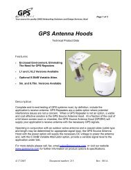
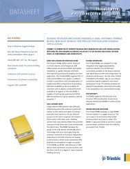
used for firmware updates. Figure 2-1 displays the numbering for the<br />
DB9 connector (female). The associated numbering for the plug<br />
connector (male) is a mirror reflection of the scheme shown in<br />
Figure 2-1.<br />
Figure 2-1. DB9 socket numbering<br />
11
2: Installation<br />
Figure 2-2 on page 12, provides the numbering for the power/data<br />
connector. The associated numbering for the plug connector is a mirror<br />
reflection of the scheme shown in Figure 2-2 on page 12.<br />
Figure 2-2. Power/data connector numbering for R1x1 series<br />
Note: For successful communication, the baud rate of the<br />
Crescent <strong>R100</strong> serial ports must be set to match that of the<br />
devices to which they are connected. Table 2-1 on page 13<br />
through Table 2-3 on page 14 provides the pin configuration for<br />
the serial ports.<br />
12
Crescent <strong>R100</strong> Series <strong>User</strong> <strong>Guide</strong><br />
Factory Parameters<br />
Table 2-1 on page 13 through Table 2-6 on page 16 identify the pin-outs<br />
and Crescent <strong>R100</strong> configuration.<br />
Table 2-1: Port A pin-out, DB9 connector pin number description<br />
for Crescent <strong>R100</strong>, R110, R120 and R130<br />
Pin<br />
Function<br />
1 Not connected<br />
2 Transmit data Port A<br />
3 Receive data Port A<br />
4 Not connected<br />
5 Signal ground<br />
6 Not connected<br />
7 Not connected<br />
8 Not connected<br />
9 5V output, 350 mA MAX<br />
Table 2-2: Port B pin-out, DB9 connector pin number description<br />
for the <strong>R100</strong>, R110, R120 and R130<br />
Pin<br />
Function<br />
1 Not connected<br />
2 Transmit data Port B<br />
3 Receive data Port B<br />
4 Not connected<br />
5 Signal ground<br />
6 Event marker<br />
13
2: Installation<br />
Table 2-2: Port B pin-out, DB9 connector pin number description<br />
for the <strong>R100</strong>, R110, R120 and R130<br />
Pin<br />
Function<br />
7 Not connected<br />
8 Not connected<br />
9 1 PPS<br />
Table 2-3: Power/data connector pin-out, pin number description<br />
for R101 and R121<br />
Pin<br />
A<br />
B<br />
C<br />
D<br />
E<br />
F<br />
G<br />
H<br />
Description<br />
Power<br />
1 PPS<br />
Port A Tx<br />
Port A Rx<br />
Port B Tx<br />
Port B Rx<br />
<strong>Manual</strong> mark<br />
Ground<br />
14
Crescent <strong>R100</strong> Series <strong>User</strong> <strong>Guide</strong><br />
Table 2-4: DGPS options<br />
DGPS option<br />
SBAS (WAAS, EGNOS, MSAS, etc)<br />
e-Dif<br />
Beacon (only on R110 and R130)<br />
External RTCM<br />
L-Band (only on R120, R121 and R130)<br />
L-Dif<br />
Table 2-5: Serial port settings<br />
Serial<br />
port<br />
Baud<br />
rate<br />
Data<br />
bits<br />
Parity<br />
Stop<br />
bit<br />
Interface<br />
level<br />
Serial Port<br />
A and B<br />
4800<br />
9600<br />
19200<br />
38400<br />
57600<br />
8 None 1 R2-232C<br />
15
2: Installation<br />
Table 2-6: GPS message output options<br />
GPS Message Update rate Max DGPS age Elevation mask<br />
Hemisphere GPS<br />
Binary<br />
From 1 Hz to 20 Hz 259,200 seconds 5°<br />
NMEA 0183 GGA From 1 Hz to 20 Hz 259,200 seconds 5°<br />
NMEA 0183 GLL From 1 Hz to 20 Hz 259,200 seconds 5°<br />
NMEA 0183 GSA 1 Hz 259,200 seconds 5°<br />
NMEA 0183 GST 1 Hz 259,200 seconds 5°<br />
NMEA 0183 GSV 1 Hz 259,200 seconds 5°<br />
NMEA 0183 RMC 1 Hz 259,200 seconds 5°<br />
NMEA 0183 RRE 1 Hz 259,200 seconds 5°<br />
NMEA 0183 VTG From 1 Hz to 20 Hz 259,200 seconds 5°<br />
NMEA 0183 ZDA 1 Hz 259,200 seconds 5°<br />
Serial and USB Ports<br />
The Crescent <strong>R100</strong> features two serial ports. Some models also support<br />
USB. The ports handle communication to and from the Crescent <strong>R100</strong>.<br />
The ports may be configured for a mixture of NMEA 0183, binary data<br />
and RTCM SC-104 data.<br />
16
Crescent <strong>R100</strong> Series <strong>User</strong> <strong>Guide</strong><br />
Custom Configuring the Crescent <strong>R100</strong><br />
All aspects of the Crescent <strong>R100</strong> may be configured through the serial<br />
port with the use of Hemisphere GPS commands. Many aspects of the<br />
Crescent <strong>R100</strong> receiver can be configured. Please refer to Hemisphere<br />
GPS’ GPS Technical Reference for all the details.<br />
Environmental Considerations<br />
The Crescent <strong>R100</strong> is designed to be placed indoors. It is, however,<br />
splash proof in case of accidental exposure. The antenna is designed to<br />
be used outdoors. See Table B-4 in the Appendix for the environmental<br />
specifications.<br />
Note: The changes made to the Crescent <strong>R100</strong> via the serial port<br />
will not be saved to the memory for subsequent power-up<br />
unless a save command is issued ($JSAVE). If changes are made<br />
via the menu system, they will automatically be saved.<br />
Note: Contact a local Hemisphere GPS dealer for more<br />
information regarding the use of Hemisphere GPS commands<br />
and customized configuration.<br />
17
2: Installation<br />
18
3: Operation<br />
Power-up<br />
LEDs<br />
Menus
3: Operation<br />
Introduction<br />
The Crescent <strong>R100</strong> was created for easy operation. This chapter<br />
provides information on the following topics:<br />
• How to power-up the Crescent <strong>R100</strong><br />
• The LEDs<br />
• The Crescent <strong>R100</strong>’s Main Menu and Differential Menu<br />
20
Crescent <strong>R100</strong> Series <strong>User</strong> <strong>Guide</strong><br />
Power-up<br />
To power-up the Crescent <strong>R100</strong>:<br />
1. Connect the ends of the Crescent <strong>R100</strong> power cable to a clean<br />
power source providing between 8 and 36 VDC.<br />
2. Turn on the system by pressing the on/off switch on the back panel.<br />
The Crescent <strong>R100</strong> accepts an input voltage between 8 and 36 VDC<br />
via the power cable. The supplied power should be continuous and<br />
clean for best performance. Table B-1 in the Appendix provides the<br />
power specifications of the Crescent <strong>R100</strong>.<br />
Note: We suggest that a weather-tight connection and<br />
connector be used if the connection will be located outside.<br />
Warning!<br />
Be careful not to provide a voltage higher than the input range<br />
(36 VDC). This will damage the receiver and will void the<br />
warranty.<br />
Warning!<br />
Do not attempt to operate the Crescent <strong>R100</strong> with the fuse<br />
bypassed. Such a modification will void the product warranty.<br />
The Crescent <strong>R100</strong> features reverse polarity protection to prevent<br />
damage if the power leads are accidentally reversed. With the<br />
application of power, the Crescent <strong>R100</strong> will proceed through an<br />
internal start-up sequence, however, it will be ready to<br />
communicate immediately.<br />
Note: The first start-up can take from 5 to 15 minutes depending<br />
on the location. Subsequent start-ups will output a valid position<br />
within 1 to 5 minutes depending on the location and time since<br />
the last start-up.<br />
21
3: Operation<br />
Note: The Crescent <strong>R100</strong> can take up to five minutes for a full<br />
ionoshperic map to be received from SBAS. Optimum accuracy<br />
will be obtained once the Crescent <strong>R100</strong> is processing corrected<br />
positions using complete ionospheric information.<br />
22
Crescent <strong>R100</strong> Series <strong>User</strong> <strong>Guide</strong><br />
LEDs<br />
The Crescent <strong>R100</strong> uses three LEDs. The LED functions are defined as:<br />
• Power Indicator LED: red. This LED will<br />
illuminate when the Crescent <strong>R100</strong> is powered.<br />
• GPS Lock Indicator LED: yellow. This LED will<br />
remain illuminated once the Crescent <strong>R100</strong><br />
achieves a solid GPS lock.<br />
• DGPS Position Indicator LED: green. This LED<br />
will illuminate solid green when the receiver<br />
has achieved a differential position and a<br />
pseudo range residual of better than 10.0<br />
meters (32.8 feet). If the residual value is worse<br />
than the current threshold, the green LED will<br />
blink indicating that differential mode has been<br />
attained, but that the residual has not met the<br />
threshold.<br />
23
3: Operation<br />
Main Menu<br />
The menu system on the <strong>R100</strong> is designed for easy setup and<br />
configuration of the unit in or out of the field. Most configurations can<br />
be done entirely through the menu system without having to connect to<br />
a computer or PDA. The menu software supports many different<br />
languages so that the configuration of the receiver can easily be<br />
understood.<br />
To return the menu system to the factory default configuration:<br />
1. Hold down the ENTER key on power-on until the splash screen<br />
disappears.<br />
Main Menu<br />
The main sections of the Main Menu are listed below:<br />
GPS<br />
POSITION STATUS<br />
SATELLITES<br />
CONFIGURE<br />
CONFIG WIZARD<br />
PROCEED WIZARD<br />
DELETED SAVED<br />
USE PREVIOUS<br />
CANCEL<br />
SYSTEM SETUP<br />
DISPLAY APPS<br />
DISPLAY FORMAT<br />
BAUD RATES<br />
DISPLAY LOGS<br />
SOFTWARE DISPLAY<br />
24
Crescent <strong>R100</strong> Series <strong>User</strong> <strong>Guide</strong><br />
The Crescent <strong>R100</strong>’s main menu is fully expanded on pages 25 to 28.<br />
GPS<br />
POSITION STATUS<br />
Lt<br />
Ln<br />
Hgt<br />
Hdg<br />
Vel<br />
Age<br />
Sv count<br />
Hdop<br />
Precision<br />
Res Rms<br />
Sigma-a<br />
Sigma-b<br />
Azimuth<br />
Sigma-Lat<br />
Sigma-Lon<br />
Sigma-Alt<br />
Navcnd<br />
Sar Smooth<br />
Eph Exists<br />
Eph Healthy<br />
NotUsed Prev<br />
Above Ele<br />
Diff corr<br />
No Diff Corr<br />
Dsp-arm<br />
DSP:CarLock<br />
DSP:BER<br />
DSP:DSPLock<br />
DSP:FrmSync<br />
DSP:TrkMode<br />
ARM:GPSLock<br />
ARM:DiffData<br />
ARM:ARMLock<br />
25
3: Operation<br />
ARM:DGPS<br />
ARM:Solutn<br />
GPS (continued)<br />
SATELLITES<br />
Chxx svxx elxxx<br />
Azxxx snr xx<br />
CONFIGURE<br />
Elev Mask<br />
MaskDGPSAge<br />
Data PORT A<br />
Data PORT B<br />
UTC Offset<br />
CONFIG WIZARD<br />
PROCEED WIZARD<br />
Create new<br />
Enter Name XXX<br />
Diff<br />
Data PORT A<br />
Data PORT B<br />
Elev Mask<br />
MaxDGPSAge<br />
PORT A<br />
PORT B<br />
Save to Location<br />
Not used1<br />
Not used2<br />
Not used3<br />
Not used4<br />
Not used5<br />
SAVE CURRENT<br />
Enter Name<br />
Save to Location<br />
Not used1<br />
Not used2<br />
Not used3<br />
26
Crescent <strong>R100</strong> Series <strong>User</strong> <strong>Guide</strong><br />
Not used4<br />
Not used5<br />
CONFIG WIZARD (continued)<br />
DELETED SAVED<br />
Not Used 1<br />
Not Used 2<br />
Not Used 3<br />
Not Used 4<br />
Not Used 5<br />
USE PREVIOUS<br />
Not Used 1<br />
Not Used 2<br />
Not Used 3<br />
Not Used 4<br />
Not Used 5<br />
CANCEL<br />
SYSTEM SETUP<br />
DISPLAY APPS<br />
In-Use<br />
Other<br />
SwapApplications<br />
DISPLAY FORMAT<br />
Display update<br />
LL Unit<br />
Hgt Unit<br />
Vel Unit<br />
BAUD RATES<br />
Port A<br />
Port B<br />
27
3: Operation<br />
SYSTEM SETUP (continued)<br />
DISPLAY LOGS<br />
Gga<br />
Gll<br />
Gsa<br />
Gst<br />
Gsv<br />
Rmc<br />
Rre<br />
Vtg<br />
Zda<br />
Bin1<br />
Bin2<br />
Bin80<br />
Bin93<br />
Bin94<br />
Bin95<br />
Bin96<br />
Bin97<br />
Bin98<br />
Bin99<br />
RTCM<br />
RD1<br />
SOFTWARE DISPLAY<br />
Menu System<br />
CrescentApp<br />
S/n<br />
CONTRAST<br />
ANIMATION<br />
SUBSCRIPTION<br />
FLIP DISPLAY<br />
LANGUAGE<br />
28
Crescent <strong>R100</strong> Series <strong>User</strong> <strong>Guide</strong><br />
Differential Menu<br />
The Differential Main Menu is listed below:<br />
L-DIF<br />
RTCM PORT<br />
RTCM BAUD<br />
RADIO<br />
BASE STATION<br />
REFERENCE<br />
RADIO<br />
EXTERNAL RTCM<br />
RTCM PORT<br />
RTCM BAUD<br />
DIFF<br />
SBAS<br />
SIGNAL STATUS<br />
SATELLITES<br />
DIFF<br />
BEACON<br />
SIGNAL STATUS<br />
CONFIGURE<br />
DIFF<br />
AUTONOMOUS<br />
NO DIFF SOURCE<br />
DIFF<br />
29
3: Operation<br />
E-DIF<br />
MODE<br />
STATUS (shown as “e-Dif”)<br />
RECALIBRATE (disappears and “REFERNECE” appears if in base<br />
station mode)<br />
AGE OF DIFF (disappears and “REFEENCE” appears if in base<br />
station mode)<br />
DIFF<br />
The Crescent <strong>R100</strong>’s differential hierarchy is expanded on pages 30 to<br />
32.<br />
L-DIF<br />
RTCM PORT<br />
RTCM BAUD<br />
RADIO<br />
BASE STATION<br />
REFERENCE<br />
Lt<br />
Ln<br />
Hgt<br />
Set Reference<br />
Use Current Pos<br />
RADIO<br />
EXTERNAL RTCM<br />
RTCM PORT<br />
RTCM BAUD<br />
DIFF<br />
30
Crescent <strong>R100</strong> Series <strong>User</strong> <strong>Guide</strong><br />
SBAS<br />
SIGNAL STATUS<br />
BER<br />
BER<br />
LN<br />
LN<br />
Elev<br />
Elev<br />
Az<br />
Az<br />
SATELLITES<br />
Mode<br />
PRN<br />
PRN<br />
DIFF<br />
BEACON<br />
SIGNAL STATUS<br />
F<br />
SS SRN<br />
MTP % Q<br />
Unselectee Bx<br />
ID H<br />
CONFIGURE<br />
Tune<br />
Auto Tune<br />
TuneBeaconName<br />
Africa<br />
Asia<br />
Australia<br />
Central America<br />
Europe<br />
North America<br />
South America<br />
DIFF<br />
31
3: Operation<br />
AUTONOMOUS<br />
NO DIFF SOURCE<br />
DIFF<br />
E-DIF<br />
MODE<br />
STATUS (E-DIF)<br />
RECALIBRATE<br />
AGE OF DIFF<br />
DIFF<br />
32
4: RTK/L-Dif<br />
Installation<br />
Using Crescent <strong>R100</strong> as a Base Station or Rover Receiver<br />
Operation
4: RTK/L-Dif<br />
Installation<br />
Introduction<br />
RTK and Local Differential (L-Dif) are two differential options for the<br />
Crescent <strong>R100</strong> that provide the most precise accuracy (See Appendix B<br />
for details). A local base station is required for both deferential options.<br />
Most commonly, the base station is comprised of a GPS receiver, GPS<br />
antenna, radio transmitter and power source (such as available in the<br />
Crescent MasterLink). The base station is typically set up near the<br />
working area, tracks GPS signals and broadcasts differential corrections<br />
to a radio and rover GPS receiver. The rover GPS system processes the<br />
corrections and outputs very accurate position information.<br />
34
Crescent <strong>R100</strong> Series <strong>User</strong> <strong>Guide</strong><br />
Base Station<br />
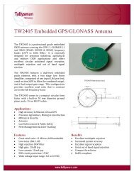
To set up the base station:<br />
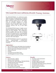
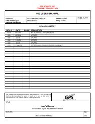
1. Place the base station at a location with no obstructions between<br />
the rover radio and base station. (See to Figure 4-1 and 4-2 on<br />
pages 35 and 36.)<br />
Figure 4-1. Base station on tripod<br />
Note: Do not place the base station near metal objects.<br />
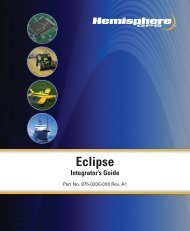
Note: Make sure the base station is at least 50 meters (160 feet)<br />
from obstructions. (See Figure 4-2 on page 36.)<br />
35
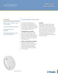
4: RTK/L-Dif<br />
5 m<br />
(16.4 ft)<br />
50 m (160 ft)<br />
Figure 4-2. Location of base station<br />
Note: Make sure the base station and rover radio have a clear<br />
line of sight up to 5 kilometers (3 miles) or less depending on the<br />
radio type when operating the L-Dif/RTK.<br />
Rover Radio Installation<br />
Note: Make sure the rover radio and the GPS antenna are at<br />
least 1 meter (3 feet) from each other.<br />
Note: The GPS antenna must not be blocked by the rover radio.<br />
Note: The rover radio must receive regular corrections<br />
from the base station, every one to two seconds (differential<br />
age), for up to 15 minutes to achieve RTK lock (maximum<br />
accuracy). Typically, a lock is achieved in under five minutes.<br />
36
Crescent <strong>R100</strong> Series <strong>User</strong> <strong>Guide</strong><br />
Using Crescent <strong>R100</strong> as a Base Station or Rover<br />
The Crescent <strong>R100</strong> can be used as a base station or rover receiver, but<br />
requires a link between the base and rover for transfer of differential<br />
corrections. The link can be wired or wireless (i.e. radio modem). The<br />
corrections must be transferred to the rover receiver through the<br />
desired link.<br />
To set up the proper application:<br />
1. Make sure the current Crescent <strong>R100</strong> application is set to RTKBAS<br />
for a base station, or RTK for a rover, by using the interface on the<br />
front panel.<br />
2. Scroll down to System Setup>.<br />
3. Click to enter the System<br />
Setup screen.<br />
4. Select Display Apps> and click<br />
to enter the Display<br />
Applications screen.<br />
37
4: RTK/L-Dif<br />
Make sure that In Use: displays<br />
either RTKBAS for a RKT or L-Dif<br />
base base station or LOCRTK for<br />
a RTK or L-Dif rover receiver. If the<br />
RTK application only appears as<br />
Other:, scroll down and select<br />
SWAPAPPLICATIONS. The<br />
desired application will be shown<br />
as In Use.<br />
Connecting the Crescent <strong>R100</strong> to a PC<br />
This application selection can also be done by using a terminal<br />
program, such as Hyper Terminal ® , SLXMon or PocketMax TM .<br />
When using direct commands from a PC, send the command $JAPP to<br />
view the current application. A response, like<br />
$>JAPP,RTKBASE,WAAS,1,2 will appear. This means that the RTKBASE<br />
application is active and WAAS is the secondary application. If the<br />
application was different and WAAS was first, such as<br />
$>JAPP,WAAS,RTKBASE,2,1, then $JAPP,other will have to be sent,<br />
which will swap applications so that correct application is used.<br />
1. Make sure the 9-pin cable from the IO-X,CIRC(F) 6-FT cable (part<br />
number 051-0160) is connected to the desired on the Crescent <strong>R100</strong><br />
receiver.<br />
2. With RTKBASE or LOCRTK as the active application, the Crescent<br />
<strong>R100</strong> automatically configures all messages necessary on Port B of<br />
the receiver for correct RTK operation. The baud rate of Port B will<br />
also be automatically set to 9600.<br />
38
Crescent <strong>R100</strong> Series <strong>User</strong> <strong>Guide</strong><br />
Connecting Crescent <strong>R100</strong> to a Base Station or Rover Via<br />
Cable<br />
The steps in the preceding section allows the Crescent <strong>R100</strong> receiver to<br />
be used as a base station or rover either with or without a radio<br />
connection.<br />
To use a wired connection:<br />
1. Connect the Crescent <strong>R100</strong> to the base station, or rover, with a<br />
9-pin serial cable from Port B of the base station to Port B of the<br />
rover receiver using a null modem adaptor.<br />
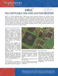
Connecting Crescent <strong>R100</strong> Via a Wireless Connection<br />
The Crescent <strong>R100</strong> can be connected through a wireless connection in<br />
two ways:<br />
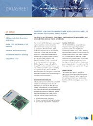
1. Use the MasterLink rover radio cable (part number 051-0160) to<br />
connect the MasterLink rover radio to the Crescent <strong>R100</strong>. (See<br />
figure 4-3 below.)<br />
MasterLink<br />
radio<br />
Crescent <strong>R100</strong><br />
data<br />
Crescent <strong>R100</strong><br />
power<br />
power<br />
lead<br />
Figure 4-3. MasterLink rover radio cable<br />
39
4: RTK/L-Dif<br />
2. Use a wireless connection. This wireless connection must meet<br />
these requirements:<br />
• Non-interference with GPS<br />
• Serial connection set to 9600,N,8,1<br />
• Enable throughput of at least 300 bytes per second<br />
Note: We recommend testing with a wired condition prior to<br />
using a third party wireless connection.<br />
Note: Make sure both the rover radio and base station are on<br />
the same channel or frequency in order for the rover radio to<br />
receive corrections from the base station.<br />
40
Crescent <strong>R100</strong> Series <strong>User</strong> <strong>Guide</strong><br />
Operation<br />
This section deals with the RTK operation after connecting to the<br />
Crescent <strong>R100</strong>.<br />
The status LEDs indicate the following:<br />
• Yellow: tracking GPS.<br />
• Flashing green: differential has been attained, but the residual<br />
has not met the threshold.<br />
• Solid green: RTK lock.<br />
The Crescent <strong>R100</strong> will output standard NMEA messages through Port<br />
A as desired. Set the message and port output as required by the usersupplied<br />
interface.<br />
41
4: RTK/L-Dif<br />
42
Appendix A: Troubleshooting
Appendix A: Troubleshooting<br />
Troubleshooting<br />
Table A-1 provides a checklist to troubleshoot common problems and<br />
their solutions for the Crescent <strong>R100</strong>.<br />
Table A-1: Troubleshooting<br />
Problem<br />
Receiver fails to<br />
power<br />
Possible solution<br />
• Verify polarity of power leads<br />
• Check integrity of power cable<br />
connections<br />
• Check power input voltage<br />
(8 - 36 VDC)<br />
• Check current restrictions imposed by<br />
power source (maximum is<br />
250 mA @ 12 VDC)<br />
• Press the POWER button<br />
No data from<br />
Crescent <strong>R100</strong><br />
• Check receiver power status<br />
(red LED)<br />
• Check integrity and connectivity of<br />
power and data cable connections<br />
• The volume of data requested to be<br />
output by the Crescent <strong>R100</strong> could be<br />
higher than what the current baud rate<br />
supports. Try using 19,200 or higher as<br />
the baud rate for all devices.<br />
No GPS lock • Check integrity of cable connections<br />
• Verify antenna’s clear view of the sky<br />
44
Crescent <strong>R100</strong> Series <strong>User</strong> <strong>Guide</strong><br />
Table A-1: Troubleshooting<br />
Problem<br />
Possible solution<br />
No SBAS lock • Check integrity of cable connections<br />
• Verify antenna’s clear view of the sky<br />
• Check SBAS visibility map<br />
No beacon lock • Check beacon listings to ensure<br />
proximity to a beacon station<br />
• Ensure there are no sources of<br />
interference nearby<br />
• Check antenna connections<br />
• Verify MSK rate is set correctly<br />
• Verify frequency of transmitting beacon<br />
• Select alternate antenna position<br />
No OmniSTAR<br />
VBS lock<br />
• Subscription activated and not expired<br />
• Check antenna connections<br />
• Verify antenna’s clear view of the sky<br />
45
Appendix A: Troubleshooting<br />
46
Appendix B: Specifications
Appendix B: Specifications<br />
Crescent <strong>R100</strong> Specifications<br />
Table B-1 to B-5 on pages 48 to page 50, provides the power,<br />
mechanical, communication, environmental and DGPS specifications<br />
for the Crescent <strong>R100</strong>.<br />
Table B-1: Power specifications<br />
Item<br />
Input voltage<br />
Power consumption<br />
Current consumption<br />
Specification<br />
8 - 36 VDC<br />
< 3 W @ 12 VDC (typical)<br />
250 mA @ 12 VDC (typical)<br />
Table B-2: Receiver mechanical specifications<br />
Item<br />
Height<br />
Width<br />
Length<br />
Weight<br />
Specification<br />
45 mm (1.77 in)<br />
114 mm (4.49 in)<br />
160 mm (6.30 in)<br />
0.54 kg (1.19 lbs)<br />
Table B-3: Environmental specifications<br />
Item<br />
Operating temperature<br />
Storage temperature<br />
Humidity<br />
Specification<br />
-32° C to +74° C<br />
(-25.6° F to +165.2° F)<br />
-40° C to +85° C<br />
(-40° F to +185° F)<br />
95%, non condensing<br />
48
Crescent <strong>R100</strong> Series <strong>User</strong> <strong>Guide</strong><br />
Table B-4: GPS sensor specifications<br />
Item<br />
Receiver type<br />
Channels<br />
Update rate<br />
Specification<br />
L1, C/A code with carrier phase<br />
smoothing (Patented COAST technology<br />
during differential signal outage)<br />
12-channel, parallel tracking<br />
or<br />
10-channel, GPS<br />
2-channel, SBAS<br />
1 - 20 Hz<br />
Horizontal accuracy • < 0.6 m 95% confidence<br />
(DGPS) *<br />
• < 2.5 m 95% confidence<br />
(autonomous) **<br />
• 1.5 cm + 1 ppm 95% accuracy<br />
(RTK)*<br />
Differential options<br />
SBAS tracking<br />
Start up time<br />
Satellite reaquisition<br />
SBAS, e-Dif, L-Dif, Radio Beacon,<br />
L-Band, Autonomous, External RTCM,<br />
RTK<br />
2-channel, parallel tracking<br />
~60 s (no almanac and RTC)<br />
< 1 s<br />
* Depends on multipath environment, number of satellites in view,<br />
satellite geometry, baseline length (for local services) and ionospheric<br />
activity<br />
**Depends on multipath environment, number of satellites in view,<br />
satellite geometry and ionospheric activity.<br />
49
Appendix B: Specifications<br />
Table B-5: Communication specifications<br />
Item<br />
Serial ports<br />
Pulse output<br />
Description<br />
2 full duplex RS232, 1 USB<br />
1 PPS (HCMOS, active high, rising<br />
edge sync)<br />
Baud rates 4800 - 57600<br />
Differential correction<br />
I/O protocol<br />
Data I/O protocol<br />
Event mark output<br />
RTCM SC-104, Hemisphere GPS<br />
proprietary<br />
NMEA 0183 and Hemisphere GPS<br />
binary and RTCM<br />
HCMOS, active low, falling edge sync,<br />
10 k-ohm, 10 pF load<br />
50
Appendix C: Accessories
Appendix C: Accessories<br />
Crescent <strong>R100</strong> Accessories<br />
Tables C-1 and C2 provide the Crescent <strong>R100</strong> unit numbers and the<br />
available accessories for the Crescent <strong>R100</strong>.<br />
Table C-1: Crescent receivers<br />
Part Number<br />
Accessories<br />
803-0047 Crescent <strong>R100</strong><br />
803-0048 Crescent R110<br />
803-0049 Crescent R120<br />
803-0050 Crescent R130<br />
803-0043 Crescent R101<br />
803-0044 Crescent R121<br />
Table C-2: Crescent <strong>R100</strong> part accessories<br />
Part Number<br />
Accessories<br />
050-0011 Data cable (DB-9)<br />
051-0160 L-Dif cable (radio to serial, power and<br />
external power)<br />
052-0005 Antenna cable, 5 m (16.4 ft) (TNC-TNG)<br />
054-0009 Power cable (unterminated), 6.7 m<br />
(21.98 ft)<br />
054-0093 Power cable (weatherpack termination)<br />
600-1021 Threaded adapter, 1.59 cm to 2.54 cm (5/8<br />
in to 1 in)<br />
602-1005 Mounting brackets<br />
52
Crescent <strong>R100</strong> Series <strong>User</strong> <strong>Guide</strong><br />
Table C-2: Crescent <strong>R100</strong> part accessories<br />
Part Number<br />
Accessories<br />
725-0007 Magnetic mount<br />
804-3030 A30 antenna<br />
804-3032 A20 antenna<br />
875-0173-000 Crescent <strong>R100</strong> <strong>User</strong> <strong>Guide</strong><br />
53
Appendix C: Accessories<br />
54
www.hemispheregps.com<br />
e-mail: info@hemispheregps.com