Measuring - sensitec
Measuring - sensitec
Measuring - sensitec

You also want an ePaper? Increase the reach of your titles
YUMPU automatically turns print PDFs into web optimized ePapers that Google loves.
Process Instrumentation<br />
and<br />
Automation<br />
<strong>Measuring</strong> Systems<br />
for Process Monitoring<br />
and Quality Assurance<br />
in Manufacturing,<br />
Assembly and<br />
Test Stands
Kistler –<br />
Your Partner for Efficiency and Quality<br />
Sensors and systems for measuring forces<br />
and torques, analyzing force-displacement<br />
and force-time characteristics, and documenting<br />
quality data during assembly and<br />
product testing are just a few elements<br />
of the solutions for the sector provided<br />
by Kistler Instruments AG. From our<br />
headquarters in Switzerland, we supply<br />
assembly and testing technology as<br />
well as specific sensors and monitoring<br />
systems for combustion engines, automotive<br />
engineering, plastics processing and<br />
biomechanical engineering.<br />
Year after year the company invests 10 %<br />
of its sales in R&D to facilitate technically<br />
innovative yet cost-effective state of the<br />
art solutions.<br />
With a combined workforce of around<br />
1 050, the Kistler Group is the world<br />
market leader in dynamic measurement<br />
technology. Twenty three group companies<br />
worldwide and more than 30<br />
distributors ensure close contact with the<br />
customer, individual application engineering<br />
support and short lead times.<br />
Kistler’s core competence lies in the development,<br />
production and implementation<br />
of sensors for pressure, force and acceleration<br />
measurement. Kistler electronic<br />
systems and expertise used for conditioning<br />
measurement signals allow analysis,<br />
control and optimization of physical processes<br />
as well as enhancement of product<br />
quality for the manufacturing industry.<br />
2 www.kistler.com
Contents<br />
A Clear Focus on 100 % Quality<br />
Process Monitoring in Assembly and Testing Technology 6<br />
XY-Monitors for Assembly and Testing Technology 8<br />
Functionality of XY-Monitors 10<br />
Process Monitoring with NC Joining Systems in Assembly Technology<br />
Compact NC Joining Systems and General-Purpose Manual Workstation 16<br />
Kistler Measurement Technology<br />
Basics of Piezoelectric Measurement Technology 18<br />
Basics of Strain Gage Measurement Technology 27<br />
Basics of Calibration 31<br />
Accuracy Evaluation 36<br />
Using Force and Torque Measurement Technology<br />
Monitoring Press-Fitting Processes 38<br />
Testing Rotary and Spring-Loaded Switches 41<br />
Monitoring Assembly of the Steering Column 44<br />
Assembling High-Frequency Connectors 48<br />
Fully Automated 100 % Testing of Gearboxes 50<br />
Gearbox Endurance Test for Landing Flap Systems 52<br />
Application Example of NC Joining Systems<br />
Fast, Flexible and Firm Joining 54<br />
NCFT for Lowest Joining and Test Forces using<br />
Wireless Signal Transmission 56<br />
Other Force and Torque Applications in Manufacturing,<br />
Assembly and Testing 58<br />
Product Range and Details<br />
Selection Criteria for Force Sensors 60<br />
Selection Criteria for Torque Sensors 64<br />
Kistler CAD Download Service 65<br />
Selection Criteria for Charge Amplifiers 66<br />
Selection Criteria for XY-Monitors 67<br />
<strong>Measuring</strong>: Sensors 68<br />
Amplifying: Charge and <strong>Measuring</strong> Amplifiers 116<br />
Analyzing: Monitoring and 124<br />
Documentation Systems<br />
Manufacturing: Electromagnetic 132<br />
NC Joining Systems<br />
Connecting: Cables 145<br />
Accessories 156<br />
Technical Literature 180<br />
Product Overview by Type Numbers 181<br />
www.kistler.com 3
A Clear Focus on 100 % Quality<br />
QUALITY JOINING powered by Kistler is the mark of 100 % quality when it comes to joining and assembly.<br />
It stands for zero-defect production with force and torque curves, for process and quality monitoring on the<br />
basis of force and torque, irrespective of the workpiece, machine, tools or jigs and fixtures.<br />
The ever increasing demands for quality<br />
and precision in industrial manufacturing<br />
and tight competition call for the whole<br />
production chain to be optimized and<br />
checked. Furthermore, companies must<br />
meet the continuously rising quality standards<br />
within the context of a zero-defect<br />
strategy. The integrated process monitoring<br />
system checks, during the respective<br />
process step, has proven to be the most<br />
economical solution towards quality<br />
assurance.<br />
The use of Kistler measurement and<br />
system technology guarantees that these<br />
requirements are satisfied, thereby assuring<br />
a zero-defect production in joining,<br />
assembly and testing technology – with a<br />
clear focus on 100 % quality at all times.<br />
In the automotive industry, aircraft<br />
construction and medical technology, to<br />
name just a few, quality is vital and strict<br />
standards are therefore set (i.e., ISO/TS<br />
16949). Especially in cases where many<br />
individual components converge into one<br />
product, it is important that these are already<br />
tested by the suppliers as this is the<br />
only way to guarantee the quality of the<br />
end-product. Here it is absolutely essential<br />
that monitoring systems are integrated<br />
into production.<br />
4 www.kistler.com
QUALITY TESTING is the mark of 100 % quality in production testing. It stands for zero-defect production<br />
through uninterrupted quality testing on the basis of force and torque – irrespective of the make of testing<br />
station. The quality tests can be implemented at all testing stations and test stands.<br />
QUALITY JOINING<br />
The joining and assembling of these<br />
individual components to produce an<br />
end-product must however be monitored<br />
and tested. Force and torque sensors<br />
record these assembly processes and<br />
transmit them to the relevant monitor<br />
systems, i.e. maXYmos, for evaluation.<br />
Direct monitoring within the process step<br />
means that deviations can be detected<br />
and corrected immediately by taking<br />
targeted measures. Quality defects are<br />
detected at an early stage, thus avoiding<br />
additional cost-intensive assembly steps.<br />
Missing parts can be discharged immediately<br />
and reworked if necessary.<br />
QUALITY TESTING<br />
Thanks to prior tests that have been<br />
carried out during the production and<br />
assembly of individual components,<br />
defective end-products are nearly ruled<br />
out. It is nevertheless essential that<br />
the functionality of the end-product<br />
is checked. The final inspection of<br />
pre-assembled shock absorbers, involves<br />
checking that they comply with the<br />
damping characteristics of a normal forcedisplacement<br />
curve. Kistler sensors and<br />
XY-monitors assume this task too.<br />
Uninterrupted process monitoring and<br />
uncompromising quality testing – with<br />
QUALITY JOINING and QUALITY<br />
TESTING powered by Kistler! With a clear<br />
focus on 100 % quality at all times.<br />
www.kistler.com 5
A Clear Focus on 100 % Quality<br />
Assembly processes are often accompanied<br />
by force-displacement or torquerotation<br />
angle curves. These are created<br />
when two joining partners are connected<br />
or when individual components are screwed<br />
together. Using special sensors, the<br />
relevant variables are recorded and then<br />
transmitted to a monitor unit.<br />
The ultimate aim in industrial manufacturing<br />
is zero-defect production. The requirements<br />
in respect of quality assurance<br />
and monitoring are therefore increasing<br />
all the time. Feasibility studies usually<br />
determine whether quality assurance is to<br />
be directly integrated into the production<br />
process, as this provides a means of being<br />
able to react as quickly as possible to<br />
process deviations or variations in quality.<br />
The subsequent non-destructive testing<br />
of press joints is simply not possible with<br />
many processes. This is why quality control<br />
must be integrated into the process.<br />
Assembly processes are usually characterized<br />
by dynamic force or torque curves.<br />
The piezoelectric measuring technique is<br />
well suited for recording such dynamic<br />
curves.<br />
Force monitoring during assembly<br />
The forces that occur during assembly<br />
(i.e., when joining and positioning) must<br />
be evaluated and documented for process<br />
and quality assurance purposes. With the<br />
press-fit process, the evaluation of the<br />
characteristic force-displacement curve<br />
is especially suitable for this purpose.<br />
Here, the interdependent variables, such<br />
as press-fit force and displacement are<br />
recorded and their functional correlation<br />
is evaluated. The result of the evaluation<br />
is used to eliminate bad parts that need to<br />
be reworked.<br />
The force is also measured in order to protect<br />
machines and individual workpieces<br />
from overload. Force thresholds are used<br />
for example to monitor the maximum<br />
press force.<br />
Press-fit forces can be measured either<br />
directly within the flux or indirectly via<br />
the strains of the machine structure, i.e.,<br />
a C-frame.<br />
6 www.kistler.com
Process Monitoring in Assembly and Testing Technology<br />
Advantages of Force or<br />
Torque Monitoring<br />
+ Permanent process control<br />
+ Trend analysis of process<br />
Parameters<br />
+ Prompt reaction to<br />
deviations<br />
+ Uninterrupted documentation<br />
+ Part-related traceability<br />
of process parameters<br />
Klick<br />
Kistler sensors and systems are used to test products<br />
with regard to the spring force, contact force, connector<br />
force, torque and tactile behavior (top)<br />
The electromechanical NC joining system NCFH<br />
Type 2151A... with integrated piezoelectric force<br />
monitoring automates joining and assembly<br />
processes (top)<br />
Correct torque curve is a quality characteristic of key<br />
switches. The Type 9339A... reaction torque sensor<br />
records the torque and transmits it to a XY-monitor<br />
(left)<br />
Joining systems with integrated force<br />
monitoring<br />
Electromechanical NC joining systems<br />
offer a high level of flexibility, exact positioning,<br />
extremely high repeatability and<br />
accurately defined press-fit forces. When<br />
it comes to press-fitting tasks in particular,<br />
they are increasingly supplanting the<br />
existing pneumatic and hydraulic joining<br />
systems. With the electromechanical NC<br />
joining modules with integrated forcedisplacement<br />
monitoring, Kistler offers<br />
particularly compact and precise system<br />
solutions for the joining technology.<br />
Torque-controlled screwing process<br />
Torque sensors and XY-monitors from<br />
Kistler (i.e., CoMo Torque Type 4700B...,<br />
etc.) are used to optimally monitor and<br />
log the specific torque curve during the<br />
screwing process. This avoids any overloading<br />
or preliminary damage to the<br />
screw joints, and the assembled products<br />
have greater operational reliability and<br />
quality.<br />
Quality assurance during product testing<br />
Force and torque measurements are not<br />
only taken to test and monitor production<br />
processes: During the manufacturing<br />
process, it can also be used to test finished<br />
products and its functions. Contact forces<br />
from plug-and-socket connections, actuation<br />
forces for pressure switches and keys,<br />
actuation torques for potentiometers,<br />
ignition and rotary switches or shut-offs as<br />
well as torque curves on gears and motors<br />
can hereby be called upon as a criterion<br />
with which to assess the quality. Piezoelectric<br />
sensors from Kistler are used to<br />
measure very large and very small forces<br />
or torques using the same sensor, without<br />
affecting the accuracy of the measurement.<br />
www.kistler.com 7
A Clear Focus on 100 % Quality<br />
The measurement of forces and torques<br />
during assembly makes the manufacturing<br />
and testing processes transparent.<br />
This is why the curves for force and<br />
torque against time, displacement or<br />
rotation angle are extremely suitable<br />
when it comes to creating a good/bad<br />
evaluation. They can be recorded via the<br />
relevant sensors and displayed, evaluated<br />
and documented on XY-monitors. The<br />
same applies to the testing of finished<br />
products, where the aim is to evaluate<br />
the haptic behavior during rotary or linear<br />
movements.<br />
*Available 2012<br />
For assembly processes and press-fit and<br />
screwing processes, automated production<br />
facilities and special machines are often<br />
used. In this case the quality control must<br />
also be done by machine and independent<br />
of any manual evaluation. Often mechanical<br />
quality monitoring is the only option<br />
due to the clock rates of the machines<br />
that are often high. XY-monitors such as<br />
maXYmos TL* can check up to 20 parts<br />
per second.<br />
Different factors determine when the<br />
quality of a particular production step is<br />
checked. For one thing, the quality of a<br />
production step can be checked immediately<br />
in a separate test stage. It only<br />
makes sense to use this method where<br />
non-destructive testing processes are<br />
possible. If this is not the case, checking<br />
must take place during the production<br />
step. As well as removing the need for a<br />
separate testing cycle, this method also<br />
has the advantage of being able to exactly<br />
locate the stage causing the error in the<br />
production step and able take targeted<br />
countermeasures.<br />
With certain processes, i.e., press-fit processes,<br />
it only makes sense to implement<br />
the latter testing method.<br />
8 www.kistler.com
XY-Monitors for Assembly and Testing Technology<br />
maXYmos BL<br />
Single-channel XY-monitor for force and torque sensors<br />
in assembly technology and product testing<br />
Standard monitor for the good/bad evaluation of XY curves, such as force against<br />
displacement or torque against rotation angle. Such curves arise in assembly or<br />
product testing as well as joining, engaging, snap-fit, swiveling, rotation and spring<br />
tests. Universal evaluation objects [EOs] such as UNI-BOX, LINE-X, LINE-Y and<br />
envelope curve band are available for curve evaluations. The handy size of the<br />
monitor means that it fits perfectly in the manual assembly station. It can however<br />
also be used in the automatic production line. Its very reasonable price tag makes it<br />
a very interesting choice for many applications.<br />
maXYmos TL*<br />
Multichannel XY-monitor for more complex measurement tasks<br />
in assembly technology and product testing<br />
High-end monitor for good/bad monitoring of XY curves. Very powerful evaluation<br />
objects supplementing those for the maXYmos BL are also available. This<br />
means that sophisticated curve evaluations can also be realized, i.e., from the<br />
field of product testing. Special evaluation objects can therefore for example<br />
determine the positions of two snap-in points of a slide guideway, or calculate<br />
and evaluate the distance between them. The option to upgrade up to eight<br />
pairs of XY channels means that the monitor is also designed for multichannel<br />
applications.<br />
In this case, testing after the press-fit<br />
process would inevitably involve the<br />
destruction of the joint.<br />
Advantages of quality testing during the<br />
production step:<br />
1. No need for a separate testing station<br />
2. Shorter cycle time<br />
3. Non-destructive testing<br />
4. Immediate test results<br />
5. Early countermeasures<br />
Regardless of when a testing process<br />
takes place, a different sample density is<br />
required in each case. This ranges from<br />
so-called spot measuring to the virtually<br />
uninterrupted sampling of a measuring<br />
function, i.e., y = f(x). Whereas with<br />
spot measuring, usually triggered by a<br />
trigger signal (i.e., a proximity switch on<br />
the press stamp), only one measurement<br />
value is obtained and evaluated from a<br />
measuring function, and the quality of<br />
the whole process is determined, the<br />
virtually uninterrupted sampling of a<br />
measuring function permits a much higher<br />
degree of reliability of the evaluation<br />
result. Every sampled value can therefore<br />
be used for evaluation purposes.<br />
This is the only way of obtaining a clear<br />
evaluation with regards to the quality<br />
of a joint. Too many factors are able to<br />
influence the press-fit process. In unfavorable<br />
cases, disturbance variables may<br />
overlap or, at worst, they can cancel each<br />
other out. The maXYmos monitors record<br />
the whole measurement curve, thereby<br />
allowing conclusions to be drawn about<br />
the insertion process, surface condition<br />
and, not least, the fit between the joining<br />
partners.<br />
*Available 2012<br />
www.kistler.com 9
A Clear Focus on 100 % Quality<br />
The representation, evaluation and documentation<br />
of force and torque curves in<br />
assembly and product testing are provided<br />
by special XY-monitors from Kistler.<br />
The functionality of maXYmos BL and<br />
maXYmos TL meet the different requirements<br />
concerning sensor interfaces,<br />
evaluation diversity and data interfaces.<br />
The evaluation elements of the monitors<br />
can be easily configured and can be combined<br />
in a number of different ways.<br />
XY-monitors of the maXYmos series<br />
monitor and evaluate XY curves of two<br />
variables that have to stand in a certain<br />
relation to each other. Such curves arise<br />
in applications such as the press-fitting<br />
of ball bearings, pivoting and swiveling<br />
backrests, riveting and calking casing parts<br />
or in the tactile manipulation of rotary<br />
switches.<br />
In press-fitting, for example, the typical<br />
measurement curves are recorded by<br />
force and displacement sensors, and when<br />
monitoring the swiveling processes, torque<br />
and rotation angle sensors are used.<br />
Depending on the form of these measurement<br />
curves, it is possible to determine<br />
the quality of an individual production<br />
step, module or whole product.<br />
Quality related stages of the measurement<br />
curves recorded by the measuring<br />
functions Y=f(X), Y=f(t), Y=f(X,t) or X=f(t)<br />
are analyzed by the maXYmos monitors<br />
using evaluation elements. This includes<br />
checking whether the curves pass through<br />
the evaluation elements as predefined.<br />
If they do, an "OK" (OK) is generated,<br />
otherwise a "Not OK" (NOK).<br />
Good/Bad statement based on a variety<br />
of evaluation criteria<br />
Depending on the design of the XY-monitor,<br />
many different evaluation functions<br />
can be activated and freely combined to<br />
monitor a process. For each evaluation<br />
element, the intersection of the curve with<br />
the element can be displayed as a trend<br />
or statistic in the form of a mean value,<br />
standard deviation, cp- or cpk-value.<br />
10 www.kistler.com
Functionality of XY-Monitors<br />
Type UNI-BOX<br />
Type ENVELOPE CURVE<br />
Type CALC<br />
Entry and exit side can be freely selected. No breaching<br />
of "closed" sides allowed. Each side can be defined as<br />
entry or exit<br />
The measurement curve must not breach the top and<br />
bottom line of the envelope curve band. Quick to teach<br />
evaluation element<br />
Element obtains two specified process values and<br />
performs the calculation operations, i.e., calculates the X<br />
difference between two ripples and evaluates them<br />
Type LINE-Y<br />
Type LINE-X<br />
Type NO-PASS<br />
Line must be crossed once. A value Y is monitored at<br />
the crossing point<br />
Line must be crossed once. A value X is monitored at<br />
the crossing point<br />
Line must not be crossed. Otherwise NOK and realtime<br />
signal "NO-PASS"<br />
Type GRAD-Y<br />
Type GETREF<br />
Type BREAK<br />
Y1<br />
X1<br />
X2<br />
Y2<br />
Evaluates the gradient dY/dX between two vertical<br />
lines<br />
GETREF BOX detects significant curve characteristics and<br />
delivers the XY coordinates as reference points for other<br />
EOs or as input for the CALC element<br />
Delivers NOK and online signal if there is a sudden<br />
change in gradient within an expectancy range (box)<br />
i.e., when a tool breaks<br />
The device is also used to display and<br />
save corresponding process values in<br />
numerical form. The process evaluation<br />
result (OK/NOK) is available as a control<br />
signal at digital outputs, bus or Ethernet<br />
interfaces.<br />
Evaluation objects UNI-BOX, LINE-X,<br />
LINE-Y, NO-PASS and ENVELOPE CURVE<br />
The curves of quality-relevant curve<br />
stages can be evaluated by different evaluation<br />
objects (EOs). First, the supervisor<br />
places them across a reference curve that<br />
has been classed as OK or even better<br />
across a whole batch of OK curves. The<br />
latter gives a sense of the distribution to<br />
be expected and thus the size of the evaluation<br />
element to use. maXYmos BL and<br />
maXYmos TL offer different types of EO,<br />
with each one evaluating according to<br />
different criteria. The evaluation objects<br />
UNI-BOX, LINE-X, LINE-Y, NO-PASS and<br />
ENVELOPE CURVE form the basis for all<br />
maXYmos monitors. The UNI-BOX for<br />
instance monitors whether the measurement<br />
curve enters and exits the prescribed<br />
sides of the box. It must be positioned<br />
manually via the respective curve<br />
stage. The ENVELOPE CURVE on the<br />
other hand positions itself automatically<br />
around the outer contour of a previously<br />
measured GOOD bundle of curves.<br />
Other evaluation elements<br />
With the additional evaluation elements<br />
GRADIENT, HYSTERESIS and CALCU-<br />
LATE, the XY-monitor maXYmos TL<br />
also optimally evaluates complex curve<br />
criteria. The CALCULATE element for<br />
example can calculate and evaluate the<br />
distance between two snap-in points on<br />
a force-displacement curve. GETREF elements<br />
send the positions of these snap-in<br />
points to the CALCULATE element.<br />
Extensive analyses from the PC software<br />
maXYmos PC<br />
The new PC software maXYmos PC<br />
enables the test report to be directly<br />
transferred from maXYmos to the PC<br />
and offers many functions for the display,<br />
measurement and analysis of measurement<br />
curves and process values as well as<br />
the evaluation of the process capability.<br />
www.kistler.com 11
A Clear Focus on 100 % Quality<br />
Display module (DIM)<br />
Cascadable up to eight XY channels. In<br />
this example, all MEMs are in the control<br />
cabinet and are therefore protected.<br />
MEM1 could also be positioned in the<br />
display module slot.<br />
Meas- and evaluation modules (MEM)<br />
MEM1<br />
MEM2 MEM3 MEM4<br />
.......<br />
MEM8<br />
Server<br />
Data export<br />
X<br />
Y<br />
Torque/<br />
Rotation angle<br />
X Y Y<br />
Y X<br />
Force/Displacement<br />
Pressure/Displacement<br />
Force/Time<br />
X<br />
Displacement/Time<br />
EtherNet/IP<br />
Profinet<br />
Profibus<br />
PLC<br />
Universal installation options<br />
The maXYmos TL is designed for desktop,<br />
wall, front panel and DIN rail mounting.<br />
The flexible case concept gives the machine<br />
designer ample scope. The MEM always<br />
has Profibus DP, ProfiNet, EtherNet/<br />
IP and Modebus/IP. Selections are made<br />
via the menu. Interfaces for all standard<br />
sensor types are also always mounted.<br />
Fittingly, Kistler’s program also includes a<br />
large selection of force and torque sensors<br />
or displacement and angle sensors.<br />
maXYmos TL – The system concept<br />
At the heart of the maXYmos TL is the<br />
measurement and evaluation module<br />
[MEM]. It operates as a standalone unit<br />
and is already equipped with all the<br />
measurement, evaluation, activation and<br />
data transfer functions. As a black-box<br />
module, the MEM can be fully configured<br />
via remote access.<br />
"Seeing" directly into the measurement<br />
module via the display module<br />
Using the display module [DIM] that is<br />
designed as a color touch screen, the<br />
MEM can be equipped with a graphical<br />
user interface [GUI]. Both components<br />
are coupled mechanically and electrically<br />
via the rear slot of the display module. In<br />
just a few easy steps, the MEM is pushed<br />
into the DIM and secured. The resulting<br />
compact unit turns into a fully-fledged<br />
XY-monitor for monitoring a pair of XY<br />
channels.<br />
Cascadable up to 8 pairs of XY channels<br />
Overall, the maXYmos TL can be extended<br />
to up to eight pairs of XY channels. To<br />
do this, additional MEMs are connected<br />
to the Ethernet interface via a patch<br />
cable. External switches are not needed;<br />
the cables are simply looped through.<br />
The individual pairs of channels are then<br />
displayed either individually or in so-called<br />
Split Mode, i.e., the information concerning<br />
all pairs of channels is displayed on a<br />
single screen.<br />
12 www.kistler.com
Functionality of XY-Monitors<br />
maXYmos BL<br />
Standard monitor for good/bad<br />
evaluation of XY curves<br />
The monitor that is equipped with a pair<br />
of XY channels already has functions that<br />
do justice to many standard applications<br />
for assembly and product testing. It is<br />
ideal for use at manual workstations, but<br />
also has all the interfaces necessary for<br />
integration into the automatic machine<br />
environment.<br />
The maXYmos BL records all variables that<br />
stand in a relation to each other, these are<br />
then delivered by piezoelectric or strain<br />
gage sensors via the Y channel and by<br />
potentiometric sensors via the X channel.<br />
Based on the curves, it can then monitor<br />
and evaluate the quality of a product or<br />
production step.<br />
Quality related stages of the measurement<br />
curves recorded by the measuring<br />
functions Y=f(X), Y=f(t), Y=f(X,t) or X=f(t)<br />
are analyzed using evaluation elements.<br />
It checks whether the curves that consist<br />
of a maximum of 8000 pairs of XY values,<br />
pass through the evaluation elements as<br />
prescribed. If they do, an "OK" (OK) is<br />
generated, otherwise a "Not OK" (NOK).<br />
For each measuring program or measurement<br />
curve, a maximum of 4 evaluation<br />
elements Types UNI-BOX, LINE, NO-PASS<br />
or ENVELOPE CURVE can be allocated. All<br />
evaluation elements can be edited by means<br />
of numerical entry or graphical drag<br />
and drop and then aligned to absolute or<br />
dynamic reference points.<br />
The basic version maXYmos BL is optimized<br />
for front panel mounting. An<br />
optional additional case allows mounting<br />
on a panel of a machine or on a desktop<br />
and the continuous adjustment of the<br />
viewing angle.<br />
• Piezo<br />
• Strain gage<br />
• ±10 V<br />
• Poti<br />
• ±10 V<br />
• Profibus DP<br />
• EtherNet/IP*<br />
Channel Y<br />
Channel X<br />
Fieldbus<br />
Circuit diagram of the maXYmos BL<br />
maXYmos BL at a Glance<br />
• Monitoring of up to 10 parts<br />
per second<br />
• 16 measurement programs for 16<br />
different types of part<br />
• Up to 8 000 pairs X/Y values per curve<br />
• 2 real-time outputs for X- and<br />
Y-thresholds<br />
• Dig-IO (24 V), Profibus DP, Ethernet (TCP/IP*) and USB*<br />
• Memory for historical measurement curves for NOK diagnosis<br />
• Warning messages and alarms allowing early countermeasures<br />
• Serial numbers from PLC or internal SN generator<br />
• Access protection for different user groups<br />
• Channel X: potentiometer and ±10 V*, channel Y: Piezo or Strain gage and ±10 V<br />
• Bright, high-contrast 3,5"color touch screen display<br />
• Clearly structured user interface<br />
• PC software "maXYmos PC" as support tool<br />
• Extremely good value for money<br />
For further details on<br />
maXYmos BL, see page 125.<br />
1<br />
2<br />
ZERO-X<br />
Global<br />
area<br />
1 of 16<br />
MP-01 MP-02 MP-03 MP-16<br />
Scaling 1<br />
Scaling 1<br />
Area<br />
related to<br />
MP<br />
4<br />
S1<br />
S2<br />
Measurement program<br />
START<br />
Cycle<br />
control<br />
READY<br />
S-TEST<br />
Y<br />
NO-PAS<br />
Current<br />
measurement<br />
curve<br />
Control by means Dig-IO (24 V) or fieldbus<br />
Digital IO 2<br />
IO<br />
NIO<br />
maXYmos BL<br />
Type 5867A...<br />
MP-01<br />
1) Scaling and cycle control specific to MP here. Can also be obtained from GLOBAL<br />
2) Only the most important signals are shown<br />
TARA<br />
X<br />
1 2<br />
ZERO<br />
Ethernet<br />
USB<br />
• Export of<br />
measurement data<br />
• Measurement<br />
results to<br />
USB stick<br />
• Measurement<br />
program from<br />
USB stick<br />
• Backup file<br />
to USB stick<br />
• PC software<br />
maXYmos PC<br />
*Available 2012<br />
www.kistler.com 13
A Clear Focus on 100 % Quality<br />
maXYmos TL*<br />
High-end monitor for good/bad evaluation<br />
of complex XY curves<br />
Very powerful evaluation objects<br />
supplementing the performance of the<br />
maXYmos BL are available in the form<br />
of the maXYmos TL. This means that<br />
sophisticated curve evaluations can also<br />
be realized, i.e., from the field of product<br />
testing.<br />
The maXYmos TL spectrum ranges from<br />
the single force-displacement monitoring<br />
system to sophisticated multichannel<br />
applications. Functionality and operating<br />
concept build on the maXYmos BL. Key<br />
features include: more powerful evaluation<br />
processes, variety of sensor options,<br />
freely selectable fieldbus types, extension<br />
option up to 8 pairs of channels and a<br />
large 10.4" color touch screen display.<br />
With the additional evaluation elements<br />
GRADIENT, HYSTERESIS and CALCU-<br />
LATE, it can also optimally evaluate<br />
complex curve criteria. The CALCULATE<br />
element for example can calculate and<br />
evaluate the distance between two snapin<br />
points on a force-displacement curve.<br />
GETREF elements send the positions of<br />
these snap-in points to the CALCULATE<br />
element.<br />
maXYmos TL at a Glance<br />
• Monitoring of up to 20 parts<br />
per second<br />
• 128 measurement programs for<br />
128 types of part<br />
• Up to 8 000 pairs of XY values per<br />
measurement curve<br />
• Measurement curve recorded with<br />
up to 20 000 samples/s<br />
• Real-time outputs for quick response<br />
• Powerful tools for NOK diagnosis<br />
• Diagnosis memory for up to<br />
1 000 measurement curves with<br />
batch function<br />
• Warning messages and alarms<br />
allowing timely countermeasures<br />
• Cascadable up to 8 pairs XY channels<br />
• Serial numbers from PLC<br />
or internal SN generator<br />
• Access protection for different user<br />
groups<br />
If a constant display is not required, the<br />
CoMo View<br />
MEM can also act as black-box module:<br />
setup and process display is then via VNC<br />
access using the<br />
• Channel X: potentiometer, ±10 V,<br />
Incremental encoder, LVDT or SSI,<br />
Channel Y: Piezo, strain gage or ±10 V<br />
• Bright, high-contrast 10,4"color touch<br />
screen display<br />
• Clearly structured user interface<br />
• PC software "maXYmos PC" as<br />
support tool<br />
• Good value for money<br />
maXYmos TL<br />
Type 5877A...<br />
Ethernet interfaces or one of the USB interfaces<br />
using the PC program maXYmos<br />
PC that is available as an accessory.<br />
The maXYmos TL consists of a measurement<br />
and evaluation module (MEM) and<br />
a display module (DIM). Both components<br />
can either be installed separately so<br />
that they are only connected by the monitor<br />
cable, or they can act as a compact,<br />
mechanical and electrical unit.<br />
The latter is produced by pushing the<br />
MEM into the rear slot of the DIM. This<br />
combination already provides a pair of<br />
measurements channels (XY) and all necessary<br />
interface for control, data export<br />
and remote maintenance.<br />
selected from the menu<br />
• Piezo<br />
• Strain gage<br />
• ±10 V<br />
selected from the menu<br />
• Poti<br />
• ±10 V<br />
• Incremental<br />
• LVDT<br />
• Inductive<br />
• SSI<br />
selected from the menu<br />
• Profibus DP<br />
• ProfiNet<br />
• EtherNet/IP<br />
• EtherCat<br />
Channel Y<br />
Channel X<br />
Fieldbus<br />
Global<br />
Area<br />
1 of 128<br />
MP-000 MP-001 MP-002 MP-127<br />
2<br />
Area<br />
related to<br />
MP<br />
8<br />
1<br />
S1<br />
Measurement program<br />
START<br />
Cycle<br />
control<br />
READY<br />
Y<br />
X<br />
S-TEST<br />
Digital IO 2<br />
Y<br />
NO-PAS<br />
IO<br />
NIO<br />
MP-000<br />
Current<br />
measurement<br />
curve<br />
Control by means of Dig-IO (24 V) or fieldbus<br />
TARA<br />
X<br />
1 2<br />
ZERO<br />
Ethernet TCP/IP 3 x USB Monitor<br />
LVDS<br />
+USB<br />
• Measurement<br />
results to<br />
USB stick<br />
• Measurement<br />
program from<br />
USB stick<br />
• Backup file<br />
to USB stick<br />
• PC software<br />
maXYmos PC<br />
• Export of<br />
measurement data<br />
• Remote maintenance<br />
• Other MEM modules<br />
1) Scaling and cycle control specific to MP here. Can also be obtained from GLOBAL<br />
2) Only the most important signals are shown<br />
Circuit diagram of the maXYmos TL<br />
*Available 2012<br />
For further details on<br />
maXYmos TL, see page 126.<br />
14 www.kistler.com
Functionality of XY-Monitors<br />
CoMo Torque<br />
Evaluation Instrument for Torque Sensors<br />
The CoMo Torque Type 4700B... allows<br />
synchronous acquisition of torque<br />
and speed signals of rotating strain gage<br />
torque sensors Type 4501A... to Type<br />
4504B... and KiTorq Stator Type 4541A... .<br />
CoMo Torque is ideal for industrial and<br />
R&D applications. Strain gage sensors<br />
with standardized sensitivity or voltage/<br />
frequency output can be connected<br />
directly.<br />
CoMo Torque at a Glance<br />
• Time-dependent M(t) and n(t) or j(t)<br />
measurement<br />
• Correct display for measurand (torque,<br />
speed, rotation angle, force and mechanical<br />
power)<br />
• Units: N∙mm, N∙cm, N∙m, kN∙m, N,<br />
kN, rpm, W, kW, MW, degrees and<br />
Imperial/American units<br />
• 4x20 character display<br />
• Multilingual operator guidance<br />
• High measuring accuracy of
Process Monitoring with NC Joining Systems<br />
in Assembly Technology<br />
Our goal is to integrate process monitoring<br />
into automated production. When<br />
joining by means of press-fitting, we<br />
recommend force-displacement monitoring<br />
as the tested and approved option.<br />
Electromechanical NC joining systems<br />
with integral force monitoring continue<br />
to prevail over pneumohydraulic and<br />
hydraulic systems thanks to the many<br />
advantages. For a force range up to 300 kN,<br />
Kistler offers a complete program for such<br />
joining systems – from the compact single<br />
module to the full production solution as<br />
a manual workstation with integrated NC<br />
joining systems.<br />
NCFT Type 2157B…<br />
NC joining module with integral piezoelectric<br />
force sensor with measuring<br />
ranges of 0,05 ... 1,5 kN.<br />
• Ideal for applications in the clean room,<br />
i.e., for the production of medical<br />
commodities<br />
• Force signal is transmitted by telemetry<br />
for maximum measurement accuracy<br />
NCFH Type 2151B…<br />
NC joining modules with space-saving,<br />
gearless, hollow-shaft motor and integral<br />
piezoelectric force sensor. The measuring<br />
ranges are 1 ... 60 kN, depending on size.<br />
• Short design, 2 sizes<br />
• High speed<br />
• Dynamic processes<br />
At a Glance<br />
Electromechanical NC joining systems<br />
offer considerable advantages over<br />
conventional technologies such as<br />
hydraulics or pneumatics.<br />
Process<br />
Flexibility at joining<br />
and press-fit processes<br />
Installation work<br />
Maintenance and<br />
cost of ownership<br />
Energy consumption<br />
Environmental benefit<br />
high<br />
increase<br />
low<br />
reduce<br />
For continuous monitoring of joining and<br />
press-fit processes, the force-displacement<br />
monitoring system Type 4740A... is available.<br />
It uses a wide variety of tolerance windows<br />
to evaluate the force-displacement<br />
curves of virtually any application. It also<br />
allows the analysis of all four quadrants<br />
(forward and backward movement/compression<br />
and tension force). In addition<br />
to the conventional tolerance windows,<br />
dynamic windows for evaluation on the<br />
basis of the maximum position achieved,<br />
windows for evaluating the gradient, the<br />
change in gradient, point-by-point and the<br />
mechanical work (integral of the curve),<br />
are available. The standard system has an<br />
Ethernet interface. This allows easy connection<br />
to existing process and measurement<br />
acquisition systems via<br />
I-P.M. or Q-DAS ® .<br />
The curve and associated setpoints and<br />
actual values can be documented in detail.<br />
The NC compact firmware Type 2159A<br />
loaded into the servo controller is ideal<br />
for the force-displacement evaluation of<br />
standard joining processes with a simple<br />
documentation function. For very modest<br />
capital and installation costs it facilitates<br />
integration into existing user control environments.<br />
NCFS Type 2152B…<br />
NC joining module with integral piezoelectric<br />
force sensor and two predefined<br />
measuring ranges of 25 and 15 kN.<br />
• Particularly slim design allows closely<br />
spaced individual workstations<br />
• More accurate guidance<br />
• Particularly rigid<br />
• Use in automated production facilities<br />
NCFB Type 2160…<br />
NC joining module with integral piezoelectric<br />
force sensor and two predefined<br />
measuring ranges 5, 15, 25 and 50 kN.<br />
• Reasonably priced<br />
• Rugged design<br />
• Ideal for standard joining processes<br />
NCFN Type 2153A…<br />
NC joining modules with integral strain<br />
gage force sensor for rated joining forces<br />
of 30, 60, 100, 200 and 300 kN.<br />
• Use in automated production facilities<br />
and manually controlled workstations<br />
• Optional safety brake<br />
• Several strokes available<br />
Special models available on request.<br />
Services<br />
• Worldwide support with startup<br />
• Global calibration service<br />
• Process and cycle time optimization<br />
• Maintenance contracts<br />
• Testing of customer samples<br />
16 www.kistler.com
Compact NC Joining Systems and General-Purpose<br />
Manual Workstations<br />
With the NCFH Type 2151B... with its<br />
overload safe piezoelectric force measurement<br />
technology, only two sizes cover<br />
the wide measuring range between<br />
1 ... 60 kN – a small one for up to 15 kN<br />
and a large one for up to 60 kN. The force<br />
signal employed for force-displacement<br />
monitoring gives a force-controlled<br />
movement for highly specialized joining<br />
tasks. The force control system increases<br />
the application versatility of the electromechanical<br />
NC joining system. Thus spring<br />
elements, for example, can be loaded to<br />
specific values or compensating force applied<br />
to continue the motion of a blocking<br />
ram set behavior.<br />
Two lubrication points for guide and<br />
bearing ensure very low-maintenance<br />
operation. As active deflection compensation<br />
system eliminates the effect of the<br />
bending of the spindle and customer’s<br />
assembly, the positional accuracy is no<br />
longer influenced by the force.<br />
Advantages of Piezoelectric<br />
Force Measurement<br />
The NC joining modules NCFT, NCFH,<br />
NCFS and NCFB have an integrated piezoelectric<br />
force sensor that offers several<br />
advantages:<br />
• A single electromechanical NC joining<br />
module covers a large number of<br />
measuring ranges<br />
• Preset of the correct measuring range<br />
unnecessary<br />
• Low sensitivity to disturbance variables<br />
• Wide variety of parts on a station, i.e.,<br />
makes mixed production feasible on<br />
single machine<br />
• Factor of safety against overload<br />
of up 15<br />
• Cuts spare parts inventory<br />
and design costs<br />
• High dynamic response because of<br />
high level of rigidity<br />
Mounting station of a German automotive supplier<br />
with an electromechanical NC joining module, NCFH<br />
Plus Points of Electromechanical<br />
NC Joining Systems, NCFH<br />
+ Gearing eliminated by hollow-shaft<br />
motor design<br />
+ Hollow-shaft motor assembled<br />
directly around the threaded spindle<br />
drive<br />
+ Long spindle stroke yet compact<br />
dimensions<br />
+ Active deflection compensation<br />
+ Force control system<br />
+ Standard holding brake<br />
+ Particularly dynamic operation<br />
+ Ideal for under-bench mounting<br />
For details about the<br />
electromechanical NC joining<br />
systems and manual<br />
workstations, see page 132.<br />
General-Purpose Manual Workstations<br />
with NC Joining Modules<br />
General-purpose manual workstations<br />
from Kistler are standalone workstations<br />
for joining processes with safety<br />
gate and integral force monitoring.<br />
They are designed for use in development,<br />
prototyping and small-scale<br />
production.<br />
Electromechanical NC joining modules<br />
Electromechanical NC joining modules<br />
are the core components of Kistler’s<br />
manual workstations. The six standard<br />
models with integral force-displacement<br />
monitoring cater for a very wide<br />
measuring range from<br />
0,05 ... 300 kN, thereby ensuring comprehensive<br />
coverage of requirements<br />
extending from the horological industry<br />
to mechanical engineering. Custom<br />
variants are also available.<br />
Monitoring via PC<br />
The manual workstation – NC Control<br />
Center (NCCC) – is controlled by a<br />
high-performance industrial PC with<br />
Windows ® 7.<br />
Time-tested by flexibility<br />
The manual workstation is readily<br />
adaptable to suit a wide variety of<br />
joining tasks. Any number of movement<br />
and measuring programs can be<br />
installed to facilitate changeovers. All in<br />
all, the manual workstation from Kistler<br />
is always a time-tested investment.<br />
Application areas for manual workstations<br />
in development and small batch<br />
production are:<br />
• Braking systems<br />
• Steering components<br />
• Injection systems<br />
• Drives<br />
• Electronic control<br />
• Chassis components<br />
www.kistler.com 17
Kistler Measurement Technology<br />
Kistler supplies piezoelectric, piezoresistive,<br />
capacitive and strain gage sensors.<br />
Piezoelectric designs are particularly<br />
suitable for measurement imposing<br />
extreme requirements in terms of geometry,<br />
temperature range and dynamics.<br />
Kistler therefore relies mainly on the<br />
piezoelectric principle for measuring<br />
dynamic forces in assembly and testing.<br />
Piezoelectric (derived from the Greek<br />
piezein, which means to squeeze or press)<br />
materials generate an electric charge when<br />
subjected to mechanical load. Pierre and<br />
Jacques Curie discovered the piezoelectric<br />
effect in 1880. As electric charges do not<br />
readily lend themselves to experimental<br />
research, piezoelectricity only gained<br />
practical significance in the middle of the<br />
20th century. With the help of so-called<br />
electrometer amplifiers, the charge produced<br />
by piezoelectric material could then<br />
be converted into a proportional electric<br />
voltage for the very first time.<br />
In 1950, Walter P. Kistler received a patent<br />
for the very first charge amplifier for<br />
piezoelectric signals, paving the way for<br />
exploitation of an effect that had been<br />
known for decades. The development of<br />
highly insulating materials such as Teflon ®<br />
and Kapton ® significantly improved the<br />
performance of these measuring systems<br />
and propelled the use of piezoelectric<br />
sensors into virtually all areas of modern<br />
technology and industry.<br />
Most Kistler sensors rely on a quartz force<br />
link, which basically consists of thin quartz<br />
plates, disks/washers or rods. The sensor<br />
is connected to an electronic device for<br />
converting the charge signal into a voltage<br />
signal proportional to the mechanical force.<br />
The conversion is made either by means of<br />
a separate charge amplifier or an impedance<br />
converter with coupler, which is usually<br />
integrated into the sensor.<br />
The finite insulation resistance means<br />
purely static measurements with piezoelectric<br />
sensors are not possible. However,<br />
together with suitable crystal measuring<br />
elements and signal conditioning devices,<br />
these sensors have excellent quasistatic<br />
measurement properties.<br />
The Piezoelectric Effect in<br />
Detail<br />
The term "piezoelectricity" refers to<br />
a linear electromechanical interaction<br />
between the mechanical and electrical<br />
state of anisotropic crystals that is<br />
those without a center of symmetry with<br />
lattice structure. These crystals have<br />
one or more polar axes along which the<br />
piezoelectric effect occurs as a result of<br />
an external force deforming the crystal<br />
lattice and pushing its positive and negative<br />
elements against one another. This<br />
produces an electric dipole moment.<br />
Depending on the orientation of the axes<br />
with respect to the applied force, three<br />
different effects can be discerned:<br />
• Longitudinal<br />
• Shear<br />
• Transverse<br />
18 www.kistler.com
Basics of Piezoelectric Measurement Technology<br />
Longitudinal effect<br />
A charge is developed on the surfaces to<br />
which the force is applied, where it can be<br />
measured. In the case of the longitudinal<br />
piezoelectric effect, the magnitude of the<br />
electric charge Q depends only on the<br />
applied force Fx and not on the dimensions<br />
of the crystal disks. The only way to<br />
increase this charge is to connect several<br />
disks mechanically in series and electrically<br />
in parallel. The magnitude of the output<br />
charge then becomes:<br />
Principle of the<br />
longitudinal<br />
piezoelectric effect<br />
Unloaded crystal<br />
Crystal under load<br />
Q x = d 11 · F x · n<br />
The piezoelectric coefficient d 11 is dependent<br />
on direction and indicates the<br />
crystal’s degree of force sensitivity in<br />
the direction of the corresponding axis.<br />
The position of the crystal cut therefore<br />
determines the properties and the area of<br />
application of the quartz force link. Piezoelectric<br />
elements cut to produce the longitudinal<br />
effect are sensitive to compression<br />
forces and therefore suitable for simple<br />
and sturdy sensors for measuring forces.<br />
Potential for increasing<br />
the charge output<br />
Crystal<br />
disk<br />
Shear effect<br />
Similarly to the longitudinal effect, the<br />
piezoelectric sensitivity involved in the<br />
shear effect is independent of the size<br />
and shape of the piezoelectric element.<br />
The charge is also developed on the piezo<br />
element’s loaded surfaces. In the case<br />
of a load in the x-direction applied to n<br />
elements connected mechanically in series<br />
and electrically in parallel, the charge is:<br />
Principle of the<br />
shear effect<br />
Unloaded crystal<br />
Crystal under load<br />
Q x = 2 · d 11 · F x · n<br />
Shear-sensitive piezo elements are used<br />
for sensors measuring shear forces,<br />
torque and strain. They are suitable for<br />
manufacturing sensors whose excellent<br />
performance is unaffected by temperature<br />
changes, as the changes in the stresses in<br />
the sensor structure caused by changes in<br />
the temperature act in a direction perpendicular<br />
to the sensitive shear axis.<br />
Direction of<br />
applied force<br />
z<br />
d 11 : piezoelectric coefficient<br />
( –2,3 pC/N for quartz crystals)<br />
F x : force in x-direction<br />
n: number of crystal disks<br />
www.kistler.com 19
Kistler Measurement Technology<br />
Transverse effect<br />
In the transverse effect, a force F y in the<br />
direction of one of the neutral axes y<br />
produces a charge on the surfaces of the<br />
corresponding polar axis x. In contrast to<br />
the longitudinal piezoelectric effect the<br />
magnitude of this charge, which occurs<br />
on unloaded surfaces, is dependent on<br />
the geometry of the piezoelectric element.<br />
Assuming element dimensions a and b,<br />
the charge is:<br />
Principle of the<br />
transverse<br />
piezoelectric<br />
effect<br />
Unloaded crystal<br />
Crystal under load<br />
Q y = –d 11 · F y · b/a<br />
The transverse effect therefore makes<br />
it possible to obtain a greater charge<br />
through suitable shaping and alignment<br />
of the piezoelectric elements. Elements<br />
exhibiting this effect can be used for<br />
high-sensitivity pressure, strain and force<br />
sensors.<br />
Practical<br />
exploitation<br />
Possible cutting angles in the quartz<br />
element<br />
Longitudinal<br />
cut<br />
Transverse cut<br />
Shear cut<br />
Quartz as a piezoelectric material<br />
Piezoelectric materials for sensor elements<br />
must primarily exhibit very high<br />
mechanical strength and rigidity. Another<br />
requirement is stability of the mechanical<br />
and electrical properties across a wide<br />
temperature range and for long service<br />
periods. High sensitivity, good linearity,<br />
negligible hysteresis that is the rising and<br />
falling calibration curves are identical and<br />
high electrical insulation resistance are also<br />
advantageous.<br />
In meeting all these requirements quartz<br />
is ideal for sensors. It can be synthesized<br />
and has other qualities beneficial for<br />
measurement. A synthetic quartz element,<br />
for example, can be used in temperatures<br />
of up to 400 °C. Quartz can be cut at<br />
different angles to exhibit sensitivity to<br />
compression or shear forces, depending<br />
on which of the three piezoelectric effects<br />
is to be used.<br />
Unlike piezoceramics, quartz is not pyroelectric<br />
and therefore does not produce<br />
a charge in the event of temperature<br />
changes.<br />
The quartz crystal produces a charge<br />
signal proportional to the acting force.<br />
Due to the high rigidity of the crystal, the<br />
measurement displacement is low, usually<br />
in the range of a few micrometers.<br />
The high natural frequency of the quartz<br />
element is advantageous for measuring<br />
instantaneous dynamic processes. Virtually<br />
displacement-free measurement produces<br />
minimal measuring errors when measuring<br />
slow, quasistatic phenomena.<br />
The extraordinary stability, sturdiness and<br />
compactness of quartz sensors has led to<br />
them being used not only in research and<br />
development, but also more widely for<br />
industrial production and testing.<br />
20 www.kistler.com
Basics of Piezoelectric Measurement Technology<br />
Quartz at a Glance<br />
Quartz has excellent properties for use<br />
as a force link:<br />
• High permissible surface pressure<br />
of 150 N/mm 2 or more<br />
• Withstands temperatures<br />
up to 300 °C<br />
• Very high rigidity<br />
• High linearity<br />
• Negligible hysteresis<br />
• Virtually constant sensitivity across<br />
wide temperature range<br />
• High frequency range<br />
• Withstands almost unlimited number<br />
of load cycles.<br />
Direct and indirect measurement<br />
Kistler quartz sensors are suitable for<br />
direct and indirect force measurement. For<br />
direct measurement the sensor is mounted<br />
right in the path of the force and measures<br />
the total force. This method delivers<br />
very exact measurement results, which<br />
are almost independent of the force application<br />
point. In cases where the sensor<br />
cannot be positioned directly in the path<br />
of the force, it will measure only a fraction<br />
of the total force, while the remainder<br />
passes through the structure in which it is<br />
mounted, the so-called force shunt. With<br />
indirect force measurement, strain sensors<br />
are used to indirectly measure the process<br />
force via the structural strain.<br />
For more information on this<br />
topic, please refer to page 24<br />
onwards.<br />
Force Sensors, Strain Sensors<br />
and Torque Sensors<br />
Quartz disks with piezoelectric properties<br />
can be stacked in sensors to allow the measurement<br />
of one or more force components<br />
or a torque vector. Kistler offers the following<br />
piezoelectric sensors for application in<br />
assembly and product testing:<br />
• Single-component force sensors<br />
• Multicomponent force sensors<br />
• Strain sensors<br />
• Torque sensors<br />
Single-component force sensors<br />
Single-component force sensors, which<br />
are available in different types, are particularly<br />
suitable for measuring forces in<br />
a specified direction. One variant is the<br />
so-called load washer, which is ideal for<br />
practical applications.<br />
Two lightly preloaded quartz disks are<br />
sandwiched between the base plate and<br />
Load washer<br />
Quartz force link<br />
Sensor for small<br />
forces<br />
the cover plate in a welded case. The<br />
electrode located between the two quartz<br />
disks receives the measurement signal and<br />
transmits it to the connector. Load washers<br />
are sturdy and highly versatile in application.<br />
Their central hole allows easy integration<br />
into various structures in a variety of<br />
different configurations and preloading by<br />
means of a screw.<br />
Preloaded between two special nuts, the<br />
washer forms what is termed a force link.<br />
The preloaded sensor is ideal for measuring<br />
compression and tensile forces, for example<br />
in rod assemblies. Preloaded sensors,<br />
which are supplied calibrated, are easy<br />
mounting for immediate use. Sensors for<br />
measuring small forces have an essentially<br />
different design. Slender quartz rods are<br />
mounted under preload between the parts<br />
used to introduce the force. Compared<br />
with the quartz rings used in load washers,<br />
the piezoelectric transverse effect in these<br />
slender quartz rods significantly increases<br />
the sensitivity.<br />
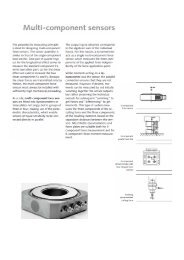
Multicomponent force sensors<br />
The piezoelectric measuring principle is<br />
also ideal for the manufacture of multicomponent<br />
force sensors. The design of<br />
the sensor is similar to that of a singlecomponent<br />
load washer. A pair of quartz<br />
washers cut for the longitudinal effect<br />
measures the normal component F z, while<br />
each of two additional pairs of washers<br />
cut for the shear effect measures one of<br />
the two shear components (F x and F y).<br />
As shear forces can only be transmitted by<br />
means of static friction, multicomponent<br />
force sensors must always be under a<br />
sufficiently high mechanical preload when<br />
mounted.<br />
Multicomponent force sensors are usually<br />
not used alone, but are mounted in a<br />
group of three or four of similar sensitivity<br />
in what is called a dynamometer or force<br />
plate.<br />
For more information on single-component<br />
force sensors, please refer to page 71 onwards.<br />
www.kistler.com 21
Kistler Measurement Technology<br />
The components of the resultant force<br />
acting on a dynamometer are proportional<br />
to the algebraic sums of the corresponding<br />
components of the individual forces generated<br />
as a result of parallel arrangement.<br />
A dynamometer is therefore nothing but a<br />
multicomponent force sensor that measures<br />
the three components of the force<br />
independently of its point of application.<br />
In order to determine the three components<br />
of the resultant moment as well, the<br />
individual sensor signals need to be added<br />
or subtracted as required. Most Kistler<br />
dynamometers and force plates are suitable<br />
for both three-component force measurement<br />
and six-component force-moment<br />
measurement.<br />
Strain sensors<br />
Strain sensors determine the process<br />
forces indirectly from the surface or structural<br />
strain. Kistler strain sensors convert<br />
strain into proportional force and generate<br />
a corresponding charge signal.<br />
Torque sensors<br />
The torque vector is measured by sensors<br />
containing several shear-effect quartz<br />
disks in a circular arrangement. The shearsensitive<br />
crystal axes of the quartz disks<br />
are tangential to the circle. The external<br />
shape of torque sensors is similar to that<br />
of single-component load washers. In<br />
order to allow transmission of the shear<br />
forces by means of static friction, the<br />
quartz disks must be mounted under high<br />
mechanical preload. Torque acting on the<br />
sensor generates tangential shear stresses<br />
in the quartz disks. As all quartz disks are<br />
connected electrically in parallel, the total<br />
output signal is proportional to the torque<br />
acting on the sensor.<br />
3-component force sensor<br />
Torque sensors are used in applications<br />
such as quality testing of rotary switches.<br />
Stationary torque dynamometers are ideal<br />
for testing pneumatic screwdrivers.<br />
Surface strain sensor for indirect<br />
force measurement<br />
3-component force link<br />
Transverse measuring pin<br />
Torque sensor<br />
Multicomponent dynamometer with four integral<br />
force sensors<br />
Longitudinal<br />
measuring pin<br />
Reaction torque sensor<br />
For more information on multicomponent<br />
force sensors, please<br />
refer to page 88.<br />
For more information on strain<br />
sensors, please refer to page 98.<br />
For more information on torque<br />
sensors, please refer to page<br />
102.<br />
22 www.kistler.com
Basics of Piezoelectric Measurement Technology<br />
Charge Amplifiers<br />
Charge amplifier<br />
Charge amplifiers convert the charge<br />
produced by a piezoelectric sensor into a<br />
proportional voltage, which is used as an<br />
input variable for monitoring and control<br />
processes. A charge amplifier basically<br />
consists of an inverting voltage amplifier<br />
with high open-loop gain and capacitive<br />
negative feedback. It has a metal<br />
oxide semiconductor field effect transistor<br />
(MOSFET) or a junction field effect<br />
transistor (JFET) at its input to create the<br />
necessary high insulation resistance and<br />
ensure a minimum of leakage current.<br />
Neglecting R t and R i , the resulting output<br />
voltage becomes:<br />
U o = -Q 1 ·<br />
C r 1 + 1 (C t + C r + C c )<br />
AC r<br />
Sensor<br />
Q<br />
U o = Output voltage<br />
A = Gain<br />
C t = Sensor capacitance<br />
C c = Cable capacitance<br />
C r = Range or negative<br />
feedback capacitor<br />
Cable<br />
R t = Time constant resistance<br />
(or insulation resistance of range capacitor)<br />
R i = Input insulation resistance<br />
(cable and sensor)<br />
Q = electric charge yielded by the<br />
piezoelectric element<br />
If the open-loop gain is sufficiently high,<br />
the quotient 1/ACr will approach zero.<br />
The cable and sensor capacitance can<br />
therefore be neglected, leaving the output<br />
voltage dependent only on the input<br />
charge and the range capacitance.<br />
U o = -Q<br />
C r<br />
The amplifier acts as a charge integrator<br />
that constantly compensates for the<br />
sensor’s electrical charge with a charge of<br />
equal magnitude and opposite polarity<br />
on the range capacitor. The voltage<br />
across the range capacitor is proportional<br />
to the charge generated by the sensor<br />
and therefore proportional to the acting<br />
measurand. In effect, the charge amplifier<br />
converts an electric charge input Q into<br />
an easily usable proportional output voltage<br />
U o . As most Kistler charge amplifiers<br />
allow adjustment of sensor sensitivity and<br />
measuring range, the measured value is<br />
displayed directly in mechanical units of<br />
the measurand and the output signal is<br />
an integer multiple of the measurand.<br />
Block diagram of a measuring chain<br />
Time constant and drift<br />
Two of the more important considerations<br />
in the practical use of charge amplifiers<br />
are time constant and drift. The time<br />
constant τ is defined as the discharge time<br />
of a capacitor by which 1/e (37%) of the<br />
initial value has been reached. The time<br />
constant of a charge amplifier is determined<br />
by the product of the capacitance<br />
of the range capacitor C r and the time<br />
constant resistance R t :<br />
τ = R t ∙C r<br />
Drift is defined as an undesirable change<br />
in the output signal over a long period of<br />
time that is not a function of the measurand.<br />
Even the best MOSFETs and JFETs<br />
have leakage currents (MOSFET: I l
Kistler Measurement Technology<br />
Force can be measured directly in the<br />
path of the force of a split component,<br />
in the force shunt mode or indirectly as<br />
a function of strain. With direct force<br />
measurement, the entire process force<br />
passes through the sensor, while with<br />
the force shunt mode, the sensor only<br />
measures part of this force. Strain sensors<br />
measure the process force indirectly as a<br />
function of strain on the surface or inside<br />
the structure of machinery.<br />
All elements through which part of the<br />
process force can pass in addition to the<br />
sensor form a force shunt n. Force shunts<br />
are also created by preloading elements,<br />
which are installed for direct measurement,<br />
but in most of these cases the shunt<br />
is less than 10 %. Measurement in the<br />
force shunt mode exploits this effect. The<br />
sensor is mounted so it only measures a<br />
fraction of the process force. The bulk<br />
of the process force passes through the<br />
machine structure. This approach allows<br />
measurement of forces greatly exceeding<br />
the measuring range of the sensor. As<br />
strain sensors only measure a negligibly<br />
small fraction of the process force, the<br />
force shunt created during indirect measurement<br />
is usually 99 % or more. If the<br />
force shunt is changed, calibration of the<br />
sensor must always be repeated, irrespective<br />
of the type of installation or sensor.<br />
<strong>Measuring</strong> Methods at a Glance<br />
Direct measurement in the path of the<br />
force<br />
The entire process force passes through<br />
the sensor (n >99 %).<br />
Direct Force Measurement<br />
in Path of Force<br />
Direct force measurement necessitates<br />
splitting the component or member<br />
perpendicular to the load path to allow<br />
mounting of the calibrated force sensor.<br />
The mounted sensor therefore has<br />
to meet the component‘s strength and<br />
rigidity requirements. The sensors used<br />
for direct force measurement are usually<br />
calibrated and preloaded prior to mounting,<br />
as installation does not affect their<br />
force shunt. Direct force measurement<br />
with calibrated and preloaded sensors is<br />
used wherever absolute force measurement<br />
is required and calibration of the<br />
system after mounting is not necessary,<br />
such as monitoring of joining forces or<br />
measurement of small forces during product<br />
testing.<br />
Direct Measurement at a Glance<br />
The sensor is mounted directly in the<br />
load path and measures the entire<br />
process force.<br />
Advantages:<br />
• High sensitivity<br />
• High measuring accuracy<br />
• High repeatability<br />
• Good linearity and low hysteresis<br />
• Wide range of preloaded, easy<br />
mounting, calibrated sensors<br />
Disadvantages:<br />
• Interference from acceleration forces<br />
when sensors are installed in moving<br />
parts<br />
• Alteration of strength or rigidity of<br />
machine<br />
• Possible restriction of workspace<br />
24 www.kistler.com
Basics of Piezoelectric Measurement Technology<br />
Force Shunt Measurement<br />
Sensors are often mounted in a force<br />
shunt configuration when large forces<br />
need to be measured or the sensor<br />
cannot be mounted directly in the force<br />
path. As the sensor then only measures<br />
part of the process force and the remainder<br />
passes into the force shunt, the<br />
measuring range can usually be narrower<br />
than that required for direct measurement<br />
and hence the solution more cost<br />
effective.<br />
Another benefit of force shunt measurement<br />
is a high level of protection against<br />
overload. In order to deliver absolute<br />
values, sensors mounted in a force shunt<br />
configuration always need to be calibrated<br />
after mounting. As the sensitivity is<br />
determined by the force shunt, and this<br />
in turn depends on the point of application<br />
of the force, calibration only remains<br />
valid while the force shunt remains<br />
unchanged. Force shunt measurement is<br />
therefore the preferred method of measurement<br />
for applications with a fixed<br />
point of application, for example for<br />
monitoring presses. It should be noted<br />
that the mounting configuration and the<br />
point of force application affect not only<br />
the sensitivity of the sensor but also its<br />
linearity and hysteresis.<br />
Force Shunt Measurement at a<br />
Glance<br />
The sensor is mounted in the structure<br />
of the machine and most of the process<br />
force usually passes into the force<br />
shunt.<br />
Advantages:<br />
• Overload protection<br />
• Cost-effective construction<br />
• Measurement of process forces up<br />
to 100/(100-n) times the sensor’s<br />
measuring range<br />
• Good measurement accuracy under<br />
constant conditions<br />
• High repeatability<br />
Disadvantages:<br />
• Measurement dependent on point of<br />
application and path of force<br />
Force shunt<br />
n [%] = 100 · F n / F p<br />
• On-site calibration required for measuring<br />
absolute values<br />
n = Force shunt (proportion of the<br />
process force not measured by<br />
the sensor)<br />
n = 0 (for unmounted sensors<br />
without preloading elements)<br />
F n = Shunt force<br />
Direct force measurement<br />
F p = Process force<br />
S 0 = Sensitivity of the unmounted<br />
sensor<br />
S = Sensitivity of the mounted<br />
sensor<br />
n<br />
S = S 0 · (1–<br />
100<br />
)<br />
Indirect force measurement<br />
n =<br />
0 %<br />
> 99 %<br />
n =<br />
100 %<br />
≈ 10 ... 99 %<br />
Force shunt measurement<br />
Sensitivity<br />
Force shunt<br />
www.kistler.com 25
Kistler Measurement Technology<br />
Indirect Force<br />
Measurement<br />
The deformation resulting from application<br />
of force to a structure can be<br />
measured as force-proportional strain.<br />
The process force is therefore determined<br />
indirectly from the surface or structural<br />
strain. Kistler strain sensors convert strain<br />
into proportional force and generate a<br />
corresponding charge signal. They are<br />
consequently often referred to as forcestrain<br />
sensors.<br />
The sensitivity is determined as electric<br />
charge Q (pC) per unit strain µε (µm/m)<br />
and is generally not calibrated, as the<br />
strain is usually negligible as a measured<br />
value. When used to determine absolute<br />
values, the sensitivity of strain measuring<br />
chains (V/kN) must always be calibrated<br />
against a force sensor as a reference.<br />
Particularly for cyclical processes it is often<br />
sufficient to monitor deviations from the<br />
force curve without any knowledge of the<br />
absolute values.<br />
Calibration<br />
Preloaded piezoelectric force sensors are<br />
calibrated by Kistler in the factory prior to<br />
shipment and are ready for direct force<br />
measurement with absolute values. Sensors<br />
mounted in a force shunt configuration,<br />
strain sensors or measuring pins,<br />
however, must always be calibrated after<br />
mounting (on-site) for measuring absolute<br />
values. Kistler offers a comprehensive<br />
calibration service for such cases.<br />
Strain sensors can be very<br />
easy mounted on a surface<br />
with just a single screw<br />
Indirect Force Measurement<br />
at a Glance<br />
Advantages:<br />
• Most convenient mounting method<br />
• Easy retrofitting of existing machines<br />
• Overload protection<br />
• Cost-efficient implementation<br />
Disadvantages:<br />
• Measurement dependent on point of<br />
application and path of force<br />
• On-site calibration required for<br />
measuring absolute values<br />
Factory and On-site Calibration<br />
at a Glance<br />
Factory and on-site calibration is only<br />
applicable to a specific, unchanging<br />
force shunt configuration.<br />
Changes to this configuration as a result<br />
of measures such as the following<br />
invalidate the calibration:<br />
• Mounting of sensor in the preloading<br />
arrangement or structure of machine<br />
• Shift in the point of force application<br />
• Changes in the force path<br />
Transverse or longitudinal measuring<br />
pins can be mounted and<br />
preloaded in specially prepared<br />
holes at a suitable point in the<br />
structure of the machine<br />
26 www.kistler.com
Basics of Strain Gage Measurement Technology<br />
The principle of operation of the strain<br />
gage is based on the physical effect of<br />
the electrical resistance of a wire changing<br />
in proportion to any change in length<br />
caused by stretching or compression.<br />
Kistler uses this principle to measure the<br />
torque on rotating shafts and in some<br />
force sensors.<br />
The strain gage was developed independently<br />
by two people in the USA in the<br />
1930s. The underlying principle had already<br />
been described by William Thomson<br />
(later Lord Kelvin) as early as 1856. The<br />
first industrially manufactured strain gages<br />
designated SR-4 were produced from the<br />
1940s onwards and very quickly found a<br />
wide range of applications.<br />
Principle of operation<br />
When the measuring wire undergoes a<br />
strain ε its length L, cross-sectional area<br />
A and specific resistance ρ of its material<br />
change. To obtain practical resistance values,<br />
the wire has to be very thin (diameter<br />
≈0,02 mm) and as long as possible. In the<br />
case of a strain gage this wire is attached<br />
to an insulating support in a meandrous<br />
pattern and provided with solderable<br />
terminals.<br />
The wire is commonly replaced with thin<br />
(≈0,005 mm) metallic foil from which the<br />
pattern is etched to form a measuring<br />
grid. This produces very small such as 1x1<br />
mm grid strain gages capable of measuring<br />
at virtually an exact point.<br />
The proportionality factor k between<br />
the strain and change in resistance to be<br />
measured is called the gage factor (k). It<br />
is constant within the elastic range of the<br />
conductor. For selected materials such as<br />
constantan this factor remains constant<br />
even when the conductor is undergoing<br />
plastic deformation.<br />
Force detector<br />
For use in strain gage load sensors the<br />
gages are bonded onto a force detector<br />
made of a selected material that exhibits<br />
linearly elastic characteristics up to the<br />
rated load. This means that the mechanical<br />
stress σ produced by the load on the<br />
force detector is linearly related to the<br />
strain ε according to Hooke‘s law:<br />
σ = E · ε<br />
L = length of measuring wire<br />
L g = length of measuring grid (= L /6 on the diagram)<br />
where the material constant E is called<br />
the modulus of elasticity. A further<br />
increase in load exceeds the elastic range<br />
and the force detector finally plastically<br />
deforms and is rendered unusable.<br />
Force detector<br />
Leads<br />
Cover<br />
Layer of adhesive<br />
Backing<br />
Layer of adhesive<br />
Ohmic resistance<br />
R = ρ·L<br />
A<br />
Change in resistance<br />
d R<br />
R<br />
= k·e<br />
The firm connection with the detector<br />
prevents the measuring wire deforming<br />
under compression. Due to its low<br />
rigidity the strain gage does not affect<br />
the behavior of the force detector under<br />
load, and can therefore resolve strains of<br />
around 1 micron/m (10 -6 m/m).<br />
Schematic of Strain Gage<br />
σ [N/m 2 ]<br />
σ B<br />
plastic range<br />
σ S<br />
"Hooke‘s linear law"<br />
elastic range<br />
σ B : Ultimate stress<br />
σ S : Yield point<br />
ε B : Elongation at rupture<br />
ε B<br />
ε [µm/m]<br />
Strain gages measure deformation of structures in<br />
linearly elastic range<br />
Strain gages soldered onto a structure<br />
www.kistler.com 27
Kistler Measurement Technology<br />
Wheatstone bridge<br />
A Wheatstone bridge is generally used to<br />
convert the very small changes in resistance<br />
caused by the deformation of a<br />
force detector in the strain gages into a<br />
voltage signal capable of evaluation.<br />
R 3<br />
U B<br />
R 4<br />
Wheatstone bridge<br />
R 1 … R 4 : Resistors or strain gages<br />
U S : Supply voltage<br />
U B : Output voltage<br />
E B : Bridge sensitivity<br />
R 1<br />
R 2<br />
U S<br />
As the temperature dependency of the<br />
bridge is a very important quality characteristic,<br />
in quarter and half bridges the<br />
fixed resistors generally also take the form<br />
of strain gages, which are geometrically<br />
very close to one another and unaltered<br />
by the load. In the event of a change<br />
in temperature the resistance values of<br />
the strain gages (for example, of R 1 and<br />
R 3 ) increase by the same amount, so the<br />
output voltage does not change.<br />
For strain gage sensors full bridges are<br />
used almost exclusively. The bridge is generally<br />
supplemented with other resistors to<br />
compensate for various factors.<br />
Advantages of Strain Gage<br />
Sensors<br />
+ Allow tensile and compression measurements<br />
without having to preload<br />
measuring elements.<br />
+ Static measurements over long<br />
period of time possible.<br />
+ Simple static calibration with weight<br />
loading.<br />
<strong>Measuring</strong> chain with strain gages<br />
The voltages produced by the bridge are in<br />
the range of a few mV. The leads for the<br />
unamplified analog signals are kept as short<br />
as possible to minimize the effect of any<br />
electromagnetic fields. A differential amplifier<br />
generally amplifies and then digitizes<br />
the voltage. Such amplifiers have a very<br />
high input resistance and high commonmode<br />
rejection.<br />
This bridge consists of four resistors or<br />
strain gages. It is supplied with voltage<br />
U S . The output voltage U B is taken off the<br />
middle of the bridge. The sensitivity of the<br />
bridge E B gives the relationship between<br />
output voltage with gage factor (k) and<br />
strain ε. Depending on the design, different<br />
numbers of resistors can take the form<br />
of strain gages. In the case of a full bridge<br />
all four resistors are strain gages and the<br />
value of their resistance is changed by an<br />
external factor such as torque or force.<br />
R 2 R 4<br />
E B = U B<br />
= k · ε<br />
U S<br />
The arrangement of the strain gages on<br />
the force detector shown in the diagram<br />
results in two gages being compressed<br />
(resistance of R 1 and R 4 reduces) and<br />
two stretched (resistance of R 3 and R 2<br />
increases). The type of force detector and<br />
the load do not always allow strain gages<br />
to be stretched and compressed with a<br />
single loading direction. In this case either<br />
two (half bridge), or even three resistors<br />
(quarter bridge) must be replaced with<br />
fixed resistors. In this case the sensitivity<br />
of the bridge is correspondingly lower.<br />
R 1 R 3<br />
An applied torque twists a measuring shaft, thereby<br />
affecting the resistors of the full bridge R 1 to R 4 and<br />
producing a voltage proportional to the torque<br />
28 www.kistler.com
Basics of Strain Gage Measurement Technology<br />
Rotating torque sensors<br />
Rotating torque sensors have two pairs<br />
of coils. The first pair transfers the power<br />
to supply the rotor, and data from stator<br />
to rotor. The digital data from the rotor is<br />
transferred to the stator by means of the<br />
other pair of coils. The electronics with<br />
the differential amplifier and the analogto-digital<br />
converter are mounted on the<br />
rotor.<br />
Rotor<br />
Supply<br />
Stator<br />
Supply<br />
Analog<br />
output<br />
A<br />
D<br />
Signal conditioning<br />
RS-232C<br />
Data<br />
Schematic of a torque sensor for rotating shafts<br />
Type 4541A... Type 4550A...<br />
KiTorq Stator KiTorq Rotor<br />
Torque measuring flange<br />
KiTorq System<br />
Type 4503A...<br />
Torque sensor<br />
Type 4504B...<br />
Torque measuring flange<br />
Type 4501A.../Type 4502A...<br />
Torque sensor<br />
www.kistler.com 29
Kistler Measurement Technology<br />
The torque on rotating shafts is measured<br />
directly in the machine‘s powertrain<br />
between a drive and a loading machine.<br />
Couplings are used to eliminate external<br />
factors such as transverse or axial forces<br />
and bending moments that can affect the<br />
measurement signal.<br />
Couplings for use between shaft and sensor<br />
differ in their flexibility. Single-flexible<br />
couplings, which can only compensate<br />
for mechanical misalignment in one<br />
direction, contrast with couplings which<br />
are flexible in two (double flexible) or all<br />
directions.<br />
Choosing the coupling<br />
The choice of coupling can be a crucial factor<br />
in terms of the quality of the measurement.<br />
For highly dynamic measurements,<br />
the coupling must be torsionally very rigid,<br />
as its torsional stiffness modifies the resonances<br />
of the mechanical structure, which<br />
can cause unwanted torsional vibrations.<br />
The cost, ease of installation/removal,<br />
maximum speed and torque are also important<br />
factors to take into account when<br />
choosing the coupling.<br />
Basic principle: The mechanical arrangement<br />
and orientation of the individual<br />
components must be as accurate as possible<br />
to ensure the couplings only have to<br />
accommodate minimal differences!<br />
Arrangement of torque measuring shafts<br />
There are two arrangements of torque<br />
measuring shafts. The floating arrangement<br />
only protects the sensor from<br />
being twisted. In this case single-flexible<br />
couplings must be used. Moreover, this<br />
arrangement should only be used for torques<br />
>50 N∙m and speeds
Basics of Calibration<br />
Sensors and measuring instruments must<br />
be calibrated at regular intervals, as their<br />
characteristics and hence the measurement<br />
uncertainties can change over time<br />
as a result of frequent use, aging and<br />
environmental factors. Instruments used<br />
for calibration are traceable to national<br />
standards and subject to a uniform<br />
international quality control. Calibration<br />
certificates document calibration values<br />
and conditions.<br />
Known<br />
input<br />
variable<br />
Product (sensor) being calibrated<br />
Output<br />
signal<br />
Safe and reliable measurement<br />
Quality assurance systems and product<br />
liability laws call for systematic monitoring<br />
of all test equipment needed for measuring<br />
quality characteristics. This is the only<br />
way of ensuring measurement and test<br />
results provide a reliable and dependable<br />
benchmark for quality control.<br />
All sensors and almost all electronic measuring<br />
devices are subject to certain measurement<br />
uncertainties. As the deviations<br />
involved can change over time, the test<br />
equipment must be calibrated at regular<br />
intervals.<br />
Force<br />
Sensitivity<br />
100 N Q or U<br />
4 pC/N<br />
Torque<br />
or<br />
100 N·m<br />
5 mV/N·m<br />
This involves determining the deviation<br />
of the measured value from an agreed<br />
reference value, which is also referred to<br />
as the calibration standard. The result of<br />
a calibration can either be used to assign<br />
the actual values of the measurand to the<br />
readings or for establishing correction factors<br />
for them. The required information is<br />
documented on the calibration certificate.<br />
Charge<br />
400 pC<br />
or<br />
Voltage<br />
500 mV<br />
Strain gages<br />
Calibration at a Glance<br />
Calibration helps ensure:<br />
Piezo<br />
• Precise and reliable measurement<br />
• Internationally comparable measurements<br />
• Similar products are metrologically<br />
compatible<br />
Basic Principle: Calibration is the use<br />
of a defined method under specified<br />
conditions to determine the relationship<br />
between a known input variable and a<br />
measured output variable.<br />
I Test<br />
FSO<br />
I Ref<br />
t<br />
∆I Ref<br />
∆I Test<br />
<strong>Measuring</strong> range I Ref<br />
Sensitivity: Ratio of the change in the signal ΔITest and<br />
the change in the reference variable ΔIRef , where I<br />
represents a charge, voltage or other indicated variable<br />
www.kistler.com 31
Kistler Measurement Technology<br />
Basic Calibration Terms<br />
I Test<br />
FSO<br />
Calibration<br />
Calibration is the use of a defined method<br />
under specified conditions to determine<br />
the relationship between a known input<br />
variable and a measured output variable.<br />
The calibration standard is the reference<br />
value. For example, the calibration of<br />
scales involves placing a defined and calibrated<br />
test weight (calibration standard)<br />
on the scales to reveal deviations in the<br />
weight reading.<br />
I Ref<br />
t<br />
+L max<br />
-L max<br />
H max<br />
Calibration certificate<br />
The calibration certificate documents all<br />
values measured during calibration and<br />
the calibration conditions.<br />
∆I Ref<br />
∆I Test<br />
<strong>Measuring</strong> range<br />
L: linearity<br />
H: hysteresis<br />
I Ref<br />
Calibration curve<br />
This curve shows the output variable of a<br />
sensor as a function of the input variable.<br />
Calibration standard<br />
The calibration standard, which is traceable<br />
to national or international "standards",<br />
is the reference value used for<br />
calibrating sensors or measuring instruments.<br />
Characteristic value<br />
Output signal of the strain gage sensor<br />
at rated load, reduced by the zero signal<br />
after mounting.<br />
Hysteresis: maximum difference between increasing load characteristic and decreasing load characteristic<br />
Linearity<br />
In practical application there is not an<br />
exactly linear (or constant) relationship<br />
between the measurand and the output<br />
variable of the sensor. The linearity L max<br />
of a sensor corresponds to the maximum<br />
deviation of the ideal from the actual output<br />
signal curve in relation to the measurand<br />
within a certain measuring range. It is<br />
expressed as a percentage of the limit of<br />
the full measuring range (% FSO).<br />
I Test<br />
Sensitivity<br />
Value of the change in output signal divided<br />
by the corresponding change in the<br />
input variable: ∆Q/∆I Ref for piezoelectric<br />
sensors or ∆U/∆I Ref in the case of strain<br />
gage sensors.<br />
FSO<br />
FSO<br />
Full Scale Output or full range signal.<br />
The difference between the output signal<br />
at zero and at the end of the measuring<br />
range.<br />
I Ref<br />
t<br />
+L max<br />
Hysteresis<br />
Maximum difference, H max, between rising<br />
load characteristic and falling load characteristic.<br />
∆I Test<br />
∆I Ref<br />
-L max<br />
L: linearity<br />
The relationship between the true value of the measurand<br />
and the output variable of the sensor is not<br />
exactly linear<br />
<strong>Measuring</strong> range<br />
I Ref<br />
32 www.kistler.com
Basics of Calibration<br />
The relationship between measurand<br />
and sensor output variable is determined<br />
by means of a simple linear regression<br />
analysis. The linearity including hysteresis<br />
indicates that the calibration curve of the<br />
loading and unloading characteristic has<br />
been used to determine the characteristic<br />
values.<br />
Best straight line<br />
Determination of a linear function passing<br />
through the origin to form the calibration<br />
curve, with two parallel straight lines with<br />
the same gradient and shortest distance<br />
apart enveloping all of the calibration<br />
values.<br />
Calibration Methods<br />
During calibration, sensors are subjected to<br />
known quantities of a physical measurand<br />
such as force or torque and the corresponding<br />
values of the output variable<br />
recorded. The magnitude of this load is<br />
accurately known, as it is measured with a<br />
traceably calibrated "factory standard" at<br />
the same time. Depending on the method,<br />
sensors are calibrated either across the entire<br />
measuring range or in a partial range:<br />
• at a single point,<br />
• stepwise at several different points or<br />
• continuously.<br />
F<br />
100 % FSO<br />
t = 200 ... 600 s<br />
Least squares function<br />
Determination of a linear function to form<br />
the calibration curve that minimizes the<br />
sum of the squares of the errors (differences<br />
between calibration curve and linear<br />
function).<br />
Step-by-step calibration involves the application<br />
of a defined load with or without<br />
unloading between successive increases or<br />
decreases, depending on the calibration<br />
method used. The process is halted after<br />
each increment until the measurement<br />
stabilizes.<br />
DKD (German calibration service),<br />
successor organization Dakks<br />
(accreditation body for the Federal<br />
Republic of Germany) accredited<br />
calibration device for torque calibrations<br />
up to 5 000 N∙m<br />
www.kistler.com 33
Kistler Measurement Technology<br />
During continuous calibration, the load<br />
is continuously increased to the required<br />
value within a defined time and then<br />
reduced to zero within the same time. A<br />
"best straight line" passing through the<br />
origin is defined for the resultant characteristic,<br />
which is never exactly linear. The<br />
gradient of this line corresponds to the<br />
sensitivity of the sensor within the calibrated<br />
measuring range.<br />
Linearity is determined by the deviation<br />
of the characteristic from the best line.<br />
Hysteresis corresponds to the maximum<br />
difference between rising and falling<br />
characteristic.<br />
Most Kistler single- or multiaxial force and<br />
torque sensors are factory calibrated.<br />
F<br />
t = 2 ... 60 s<br />
Basics of Calibration<br />
IAAC<br />
Inter American<br />
Accreditation<br />
Cooperation<br />
EA<br />
European Cooperation<br />
for Accreditation<br />
of Laboratories<br />
APLAC<br />
Asian Pacific<br />
Laboratory<br />
Accreditation<br />
Cooperation<br />
SADCA<br />
Southern African<br />
Development<br />
Coopera tion in<br />
Accreditation<br />
PAC<br />
Pacific<br />
Accreditation<br />
of Certification<br />
International standards specify the required<br />
calibration methods and measurement<br />
uncertainties.<br />
Different institutes coordinate international<br />
cooperation on calibration. They<br />
are also responsible for the accreditation<br />
of national calibration laboratories. Documentation<br />
guidelines may differ slightly<br />
from one country to another.<br />
The following calibration documents are<br />
available for most Kistler sensors:<br />
• Manufacturer‘s declaration,<br />
• CE declaration of conformity,<br />
• Factory certificate,<br />
• Test certificate,<br />
• Factory test certificate,<br />
• Calibration certificate,<br />
• SCS calibration certificate,<br />
• Traceability chart.<br />
At a Glance<br />
Kistler offers a comprehensive<br />
calibration service:<br />
• calibration of test equipment,<br />
• accredited calibration laboratory<br />
(SCS 049, DKD-37701),<br />
• extensive functional testing and<br />
• range of different calibration<br />
documents.<br />
www.kistler.com 35
Kistler Measurement Technology<br />
Numerous mechanical, electrical and<br />
climatic parameters affect the calibration<br />
result and hence the accuracy of a<br />
measuring chain. For maximum calibration<br />
accuracy, assembly errors have to<br />
be avoided and the correct position and<br />
angle of force application achieved. Factors<br />
such as the non-linearity of various<br />
electrical parameters along the measuring<br />
chain must be considered. Last but<br />
not least, temperature and humidity also<br />
have a decisive effect.<br />
Simultaneous calibration of three force<br />
components or three moments is one<br />
of the greatest challenges in calibrating<br />
multicomponent sensors. On Kistler‘s<br />
3-component calibration system the loading<br />
is applied sequentially, with the sensor<br />
being calibrated remaining in its mounted<br />
position.<br />
Influence of assembly<br />
Mechanical interference due to size or<br />
positional inaccuracies significantly affects<br />
the calibration result. Force and torque<br />
sensors are often deformed in the course<br />
of assembly. Factors such as flatness,<br />
roughness, parallelism and contact surface<br />
pressure are highly important in the<br />
transmission of force or torque. Evaluation<br />
of the effect of assembly is based on<br />
a range of individual measurements taken<br />
from a typical device to be calibrated<br />
after repeated mounting in a calibration<br />
system. The characteristic value of errors<br />
caused by these operations can be used to<br />
determine the effect of assembly on the<br />
calibration result.<br />
Non-linearity<br />
The overall characteristic of electrical<br />
devices is usually non-linear, as linear behavior<br />
of all structural components is rare.<br />
This also applies to charge calibrators,<br />
charge amplifiers and bridge amplifiers,<br />
whose very slight non-linearity affects<br />
the calibration result. Force and torque<br />
sensors also exhibit non-linear characteristics.<br />
The linearity determined by the<br />
calibration is documented on the calibration<br />
certificate and affects evaluation of<br />
the measuring uncertainties involved in<br />
calibration. The linearity of the reference<br />
sensor is already included in the measurement<br />
uncertainty and need not be further<br />
taken into account.<br />
Humidity<br />
Relative humidity influences the behavior<br />
of electronic components including the<br />
capacitors used in charge amplifiers and<br />
charge calibrators. Type approval tests<br />
record and document the thermal characteristics<br />
of electric measuring instruments.<br />
This information can be used to determine<br />
the effects of variations in humidity on the<br />
calibration result.<br />
Effective number of bits (ENOB)<br />
<strong>Measuring</strong> cards, for example, have a<br />
measuring range of –10 … 10 V and a<br />
resolution of 16 bits. The true signal is<br />
rounded up or down to the nearest bit<br />
value, which causes a maximum rounding<br />
error of half a bit.<br />
Best measurement capability<br />
Comparative calibration involves the use<br />
of a reference sensor with best measurement<br />
capability, which has a documented<br />
measurement uncertainty as a result of<br />
being calibrated against a higher standard.<br />
Prior to calibration of the sensor, the<br />
charge amplifier must also be calibrated<br />
using a precision charge calibrator to<br />
ensure that the output voltage displayed<br />
by the amplifier is matched with the<br />
charge generated by the force sensor.<br />
The absolute standard method employs<br />
a calibration system with preset physical<br />
input variable. This system also has best<br />
measurement capability.<br />
Effect of temperature<br />
Mechanical components are subject to<br />
thermal expansion and the resistance<br />
of electronic components depends on<br />
temperature. Temperature variation during<br />
the calibration process therefore has<br />
a direct effect on the result. The effect<br />
of this parameter on the sensitivity of<br />
piezoelectric sensors and the characteristic<br />
value of strain gage sensors is analyzed as<br />
part of the type approval test. Force and<br />
torque sensors using strain gages have<br />
special compensation modules to minimize<br />
thermal changes. There is also reliable<br />
data on the thermal behavior of charge<br />
calibrators and charge amplifiers. Charge<br />
calibrators have temperature compensation<br />
that makes their thermal dependence<br />
very slight.<br />
36 www.kistler.com
Accuracy Evaluation<br />
Range errors in charge amplifiers and<br />
charge calibrators<br />
The tolerance of electric components limits<br />
the accuracy of charge amplifiers and<br />
charge calibrators. It manifests itself as a<br />
range error, which depends on the preset<br />
measuring range and the measured value.<br />
The maximum range error is specified for<br />
each device.<br />
Drift<br />
The drift of a charge amplifier is a global<br />
description of the shift of the signal zero<br />
level, which is mainly due to a loss of<br />
feedback capacitor charge and leakage<br />
currents at the amplifier input. A leakage<br />
current across the insulation resistance<br />
causes an exponential decay in the feedback<br />
capacitor charge with a time constant<br />
given by the product of insulation<br />
resistance and the capacitor‘s capacitance.<br />
As a sufficiently high insulation resistance<br />
leads to a very high time constant, the<br />
problem of discharge only affects very<br />
long measuring periods. Given the drift<br />
characteristics of charge amplifiers are well<br />
known from extensive research, the peak<br />
value can be used to evaluate the effect of<br />
drift on the calibration result.<br />
Instability of charge amplifiers over time<br />
Charge amplifiers are subject to instability<br />
over time. To minimize the effect of this<br />
instability on force sensor calibration, it<br />
is advisable to calibrate in advance with<br />
a precision charge calibrator the charge<br />
amplifiers of both the reference measuring<br />
chain and the measuring chain of the<br />
device to be calibrated together with all<br />
corresponding cables, display and evaluation<br />
devices. This approach also identifies<br />
all potential influences from contacts and<br />
electrical connections within the measuring<br />
chain.<br />
Stability of charge calibrators<br />
Under normal circumstances, charge<br />
calibrators are calibrated at regular intervals<br />
(generally annually). Within these<br />
intervals the calibration values undergo<br />
slight changes, which are characteristic<br />
of specific devices and as such constant.<br />
The stability of charge calibrators must be<br />
considered in evaluating the calibration<br />
results.<br />
Calibration of strain gage sensors<br />
This requires the use of a bridge amplifier<br />
and a reference standard. Despite being<br />
balanced at the start of the calibration<br />
process the bridge amplifier is subject to<br />
a certain measurement uncertainty. The<br />
reference signal is characterized by the<br />
values shown on the calibration certificate.<br />
Crosstalk in multiaxial sensors and<br />
sensor systems<br />
Complex sensor systems such as dynamometers<br />
are generally fitted with<br />
multicomponent sensors. With such<br />
configurations crosstalk of individual variables<br />
is observed in other measurement<br />
components. With a unidirectional force<br />
load in the direction of one axis minimal<br />
signals in the direction of the other two<br />
orthogonal axes or minimal moment will<br />
be indicated. This phenomenon affects all<br />
of the possible force and moment directions<br />
and the values involved have to be<br />
taken considered in assessing measurement<br />
uncertainties.<br />
Ripple in rotating sensor systems<br />
Rotating sensor systems exhibit ripple. The<br />
value of this ripple describes the change<br />
in sensitivity as a function of the rotation<br />
angle relative to the reference point.<br />
During calibration, the angular range of a<br />
full revolution is measured with a limited<br />
number of data points, which are then approximated<br />
by an optimized interpolation<br />
curve. The difference between the interpolation<br />
curve and the measured points<br />
reflects the measurement uncertainty.<br />
Threshold<br />
The threshold is the smallest change in the<br />
input variable that leads to a discernable<br />
change in the value of the output variable<br />
of a force or torque sensor. From experience,<br />
it is two or three times the rms value<br />
of the signal noise. This noise consists<br />
of the background noise of sensor and<br />
amplifier.<br />
www.kistler.com 37
Using Force and Torque Measurement Technology<br />
The quality of the joins that are produced,<br />
for example, when bearings,<br />
cartridges and axles are press-fitted can<br />
be accurately determined using the typical<br />
press force applied along the press-fit<br />
path. XY-monitors from the maXYmos<br />
series map these curves, display them<br />
graphically and evaluate them.<br />
XY-monitoring<br />
Typical measuring curves are measured<br />
using force and displacement sensors for<br />
press-fitting, and with torque and crank<br />
angle sensors for rotational movements.<br />
All measurands that can be measured with<br />
piezo, strain gage, transmitters (±10 V)<br />
and potentiometric sensors can be recorded,<br />
displayed in relation to one another<br />
and monitored using XY-monitors from<br />
the maXYmos series. The force signal can<br />
be determined either by direct or indirect<br />
measurement. The measuring curves can<br />
Kistler Plus Points<br />
Using XY-monitors to monitor pressfit<br />
operations has the following advantages:<br />
+ Protects against the joining<br />
of defective parts,<br />
+ Greater production efficiency resulting<br />
from zero-defect production,<br />
+ Prevents damage to machine, tool<br />
and workpiece,<br />
+ Optimum control of the process<br />
using process visualization and statistical<br />
process control,<br />
+ Ability to benchmark against other<br />
processes as a result of transparent<br />
and uninterrupted documentation of<br />
production process and<br />
+ Integration in higher-level, computerassisted<br />
quality assurance systems.<br />
Fz<br />
be used to assess the quality of either a<br />
single production step, of an assembly or<br />
the product. The earlier such monitoring<br />
is started in the production chain, the<br />
better the chances of the finished product<br />
passing its final inspection. Parts can also<br />
be quarantined at an early stage and<br />
reworked. This avoids situations where<br />
they are only identified as rejects after<br />
passing through many more stages of the<br />
production process.<br />
Process evaluation<br />
The press-fit process is monitored using<br />
evaluation objects such as UNI-BOX,<br />
ENVELOPE CURVE or threshold values.<br />
These elements analyze quality-related<br />
sections of measuring curves recorded<br />
using the Y=f(X), Y=f(t), Y=f(X,t) or Y=f(t)<br />
measuring functions. A maximum of four<br />
(maXYmos BL) or ten (maXYmos TL) of<br />
these evaluation objects can be placed<br />
over a curve.<br />
The evaluation objects [EOs] assign a<br />
classification of "Good" (OK) or "Bad"<br />
(NOK), each of which can perform<br />
another monitoring function. While some<br />
must be executed in a precisely predefined<br />
direction, e.g. the UNI-BOX or ENVELOPE<br />
s<br />
Displacement sensorType 2112A...<br />
Press force sensor Type 9343<br />
for direct force measurement<br />
Surface strain transmitter Type 9238B...<br />
for indirect force measurement (alternative method)<br />
Force sensor Type 9041A<br />
for direct force measurement (alternative method)<br />
Force sensor Type 9133B...<br />
for force shunt measurement<br />
CURVE, others only produce a process<br />
value, e.g. a gradient. The latter must<br />
remain within specified tolerance limits.<br />
Assuming the direction and/or process<br />
value are observed, the evaluation objects<br />
in question produce an (OK) result. All<br />
evaluation objects can be positioned over<br />
the curve either graphically, on a Touch<br />
Display, or by specifying coordinates.<br />
Identifying suitable reference points<br />
for the distance or angle measurement<br />
system is a fundamental prerequisite for<br />
a safe and reliable process. Irrespective of<br />
which reference points can most easily be<br />
reproduced on a test object, the evaluation<br />
objects of the maXYmos monitors can<br />
reference either the absolute X-zero point<br />
or a dynamic reference point, such as<br />
the position on the blocking point or the<br />
position on the first force increase (X on<br />
Trigger-Y threshold).<br />
38 www.kistler.com
Monitoring Press-Fitting Processes<br />
The press-fitting process in this instance is monitored using the evaluation objects<br />
[EOs] "NO-PASS" (1), "ENVELOPE CURVE" (2) and "UNI-BOX" (3). The limits of<br />
the EOs are reached but not violated, so theresult is OK<br />
Should the press-fitting curve deviate from the set curve, the limits of the evaluation<br />
objects will be violated or not even reached. The result of the evalution is<br />
then NOK<br />
Process monitoring<br />
The first phase of a press-fitting operation<br />
involves loading or insertion. This operation<br />
can be monitored using a "NO-PASS"<br />
threshold (1). If the parts being joined<br />
are tilted, or incorrect parts are inserted,<br />
the force in the loading area dramatically<br />
increases. The NO-PASS threshold is<br />
violated, causing a digital output to be set<br />
straight away. This can be used to initiate<br />
a return stroke of the press. The part<br />
will be ejected and manually reworked if<br />
required.<br />
After initial positioning comes the second<br />
phase, the press-fitting operation itself.<br />
The force increases steadily following the<br />
transition from static friction to sliding friction.<br />
The reason for this is that the parts<br />
being joined overlap more and more as<br />
the press-fitting operation proceeds, causing<br />
a steady increase in the friction. The<br />
"ENVELOPE CURVE" (2) evaluation object<br />
checks whether the force levels in this<br />
area remain within limits. This ensures that<br />
the fit between the parts is in fact correct.<br />
A conical bore, for instance, would lead to<br />
a sharp increase in the press force, violating<br />
the upper line on the envelope curve<br />
and producing a NOK result.<br />
In the third phase, the blocking force and<br />
position are monitored. To do this, the<br />
curve must end in the UNI-Box (3), which<br />
is achieved by specifying "Entry: bottom"<br />
and "Exit: none".<br />
Reference curves are required in order<br />
to place the evaluation objects in the<br />
best possible position. Good parts are<br />
"calibrated" and their curves displayed<br />
as bundles. The evaluation objects can<br />
then, taking into account the spread in<br />
the respective area, be placed in the best<br />
possible positions above them.<br />
Eliminating external tolerances<br />
Evaluation results are often distorted by<br />
external tolerances. Disturbance variables<br />
like these can cause the measuring curve<br />
Product testing with maXYmos BL. Damping elements<br />
are monitored to ensure adherence to a characteristic<br />
force-displacement curve.<br />
to shift horizontally, e.g., in the direction<br />
of travel. Although the part is OK, this<br />
results in a violation of the evaluation<br />
object and hence to an NOK result. The<br />
maXYmos series monitors are therefore<br />
able to refer each evaluation object to a<br />
dynamic X-reference point as well as an<br />
absolute one. This is either the position<br />
at the first force increase (TRIGGER-Y<br />
threshold) or, retrospectively, the position<br />
at the blocking point.<br />
The maXYmos TL XY-monitoring system,<br />
which can have up to 8 cascadable<br />
channel pairs, facilitates the decentral<br />
monitoring of several simultaneously<br />
running processes and, if required, their<br />
central visualization on a common monitor.<br />
Various press-fit stations can thus<br />
be simultaneously monitored on a rotary<br />
indexing table.<br />
www.kistler.com 39
Using Force and Torque Measurement Technology<br />
Applications<br />
Press-fit operations that are monitored by<br />
XY-monitors can be found in the automobile<br />
and component supply industries,<br />
aerospace and many other sectors. Typical<br />
application areas for process monitoring<br />
include the press-fitting of<br />
• ball bushes, bearings, pinions and shafts<br />
when installing transmissions,<br />
• bearings, sleeves, seal rings, etc. when<br />
fitting steering columns,<br />
• bearing shafts when installing electric<br />
motors and injection pumps and<br />
• bearing bushings in the wash drums of<br />
washing machines.<br />
Kistler Products<br />
• Piezoelectric Type 9343 Press Force<br />
Sensor for direct measurement of<br />
press forces,<br />
• Alternative: piezoelectric<br />
Type 9133B... SlimLine Sensor for<br />
measuring the press force in force<br />
shunt,<br />
• Alternative: piezoelectric<br />
Type 9232A... strain sensor for indirect<br />
press force measurement,<br />
• Standard cable Type 1631C...,<br />
• maXYmos BL XY-monitor<br />
Type 5867A...<br />
<strong>Measuring</strong> Chains for Press-Fit Processes<br />
<strong>Measuring</strong> Connecting Analyzing<br />
Direct force<br />
measurement<br />
Displacement<br />
sensor<br />
9313AA..., 9343,<br />
9323A ... 9393A<br />
9301B ... 9371B<br />
9001A ... 9071A<br />
9081B, 9091B<br />
2112A...,<br />
2117A...<br />
2118A..., 2119A..., 2120A..., 2121A...<br />
1631C...<br />
1200A151CSP<br />
5867A...<br />
5863A1...<br />
5863A2...<br />
Shunt force<br />
measurement<br />
Displacement<br />
sensor<br />
9133B<br />
9130B... ... 9137B...<br />
9101A ... 9107A<br />
9001A ... 9071A<br />
9081B, 9091B<br />
2112A...<br />
2117A...<br />
2118A..., 2119A..., 2120A..., 2121A...<br />
1200A151CSP<br />
5867A...<br />
5863A1...<br />
5863A2...<br />
Indirect force<br />
measurement<br />
Displacement<br />
sensor<br />
9232A<br />
9233B<br />
9235B...<br />
2112A...<br />
2117A...<br />
2118A..., 2119A..., 2120A..., 2121A...<br />
1631C...<br />
1200A151CSP<br />
5867A...<br />
5863A1...<br />
5863A2<br />
Standard equipment<br />
Alternative<br />
40 www.kistler.com
Testing Rotary and Spring-Loaded Switches<br />
As automotive components with a direct<br />
bearing on safety, ignition switches, control<br />
pedals and locking systems leave no<br />
room for production errors. Torque sensors<br />
can determine the operating torque of<br />
components such as ignition switches<br />
in the course of actual production.<br />
ControlMonitors analyze this parameter<br />
as a function of rotation angle, check it<br />
against specified tolerances and reject<br />
defective products.<br />
Each and every step involved in the production<br />
of components that affect safety<br />
is monitored by sensors. Suppliers to the<br />
automotive industry can guarantee flawless<br />
operation of their components by<br />
conducting in-line tests to reliably avoid<br />
failures in the customer‘s product.<br />
Testing ignition switches with torque<br />
sensors<br />
Torque sensors can test operation of<br />
assembled ignition switches on the production<br />
line. The torque measured during<br />
rotation of the spring-loaded components<br />
must lie within specified tolerances.<br />
Torque sensors can check typical ranges,<br />
for example from 1 ... 3 N∙m, within<br />
short production cycles. The sensors are<br />
positioned pneumatically before being<br />
rotated by the required angle (such as<br />
120 °) to check the torques applied to a<br />
spring-loaded ignition switch.<br />
A reaction torque sensor Type 9339A tests ignition switches by measuring the<br />
torque from 1 … 3 N∙m against the spring preload during mass production (left)<br />
and in laboratory tests on an experimental set-up (right)<br />
M Z<br />
Ignition switch test specimen<br />
Indexing table positions switch<br />
Front part of test key<br />
Part of the test unit<br />
Test key adapter<br />
Reaction torque sensor<br />
Type 9339A<br />
Centering pin for transmission input<br />
shaft<br />
Transmission input shaft<br />
Front of electric motor enclosure<br />
Indexing table base plate, test unit<br />
Electric motor / servo drive, rotation<br />
angle controlled, monitored<br />
www.kistler.com 41
Using Force and Torque Measurement Technology<br />
Testing spring-loaded switches with<br />
force Sensors<br />
The brake pedal, clutch pedal or accelerator<br />
is equipped with between four and<br />
eight spring-loaded switches, depending<br />
on the particular model of car. They activate<br />
the brake lights and generate a signal<br />
for different vehicle control systems. The<br />
resilience of these switches can be tested<br />
in special test stands, which are equipped<br />
with sensitive sensors for small forces. The<br />
test involves the displacement-controlled<br />
movement of a sensor against the test<br />
spring by means of a servo motor.<br />
Servo drive<br />
Process monitoring via machine control<br />
If the assembly or test unit is equipped<br />
with a control system and monitor, it can<br />
be used to visualize and analyze the force<br />
or torque curve. A charge amplifier converts<br />
the charge yielded by the sensor into<br />
a proportional electrical voltage. The machine‘s<br />
control system can use this voltage<br />
as an input value. As an alternative to<br />
charge amplifiers and visualization in the<br />
machine control system, the measurement<br />
results can be analyzed with ControlMonitors<br />
such as maXYmos BL or maXYmos TL.<br />
Displacement sensor<br />
Fz<br />
Force sensor<br />
Type 9203<br />
Test specimen<br />
Force curve during a spring test using the maXYmos TL XY-monitor<br />
42 www.kistler.com
Testing Rotary and Spring-Loaded Switches<br />
Kistler Products<br />
Rotary switch testing<br />
• Standard cable Type 1631C2...<br />
• Highly sensitive Type 9339A<br />
reaction torque sensor<br />
• Single channel charge amplifier<br />
ICAM Type 5073A1...<br />
Kistler Products<br />
Pressure switch testing<br />
• Highly sensitive, preloaded<br />
Type 9203 force sensor<br />
• Standard cable Type 1631C2...<br />
• Single channel charge amplifier<br />
ICAM Type 5073A1...<br />
<strong>Measuring</strong> Chains for Testing Rotational Switches<br />
<strong>Measuring</strong> Chains for Testing Rotational Switches<br />
<strong>Measuring</strong> of<br />
reaction torque,<br />
evaluated using<br />
machine controller<br />
Monitoring of<br />
reaction torque,<br />
evaluated using<br />
maXYmos TL<br />
XY-monitor<br />
<strong>Measuring</strong><br />
<strong>Measuring</strong><br />
Connecting<br />
Connecting<br />
Amplifying<br />
Amplifying<br />
Analyzing<br />
Analyzing<br />
5073A1...<br />
5073A1... 5030A...<br />
5030A...<br />
1631C...<br />
9339A<br />
9339A 9329A ... 9389A<br />
1631C...<br />
9329A ... 9389A<br />
9339A<br />
9339A 9329A ... 9389A<br />
9329A ... 9389A<br />
1631C...<br />
1631C...<br />
5877A<br />
5877A<br />
<strong>Measuring</strong> Chains for Spring-Loaded Switches<br />
<strong>Measuring</strong> Chains for Spring-Loaded Switches<br />
<strong>Measuring</strong> of<br />
low switching force,<br />
evaluated by<br />
machine controller<br />
<strong>Measuring</strong> Connecting Amplifying<br />
Analyzing<br />
<strong>Measuring</strong> Connecting Amplifying<br />
Analyzing<br />
5073A1...<br />
9203<br />
5073A1... 5030A...<br />
9203 9205<br />
5030A...<br />
9205 9207<br />
9207 9215<br />
1631C...<br />
9215 9217A<br />
1631C...<br />
9217A<br />
Monitoring of<br />
switching force<br />
curve, evaluated<br />
using maXYmos BL<br />
XY-monitor<br />
9203<br />
9203 9205<br />
9205 9207<br />
9207 9215<br />
9215 9217A<br />
9217A<br />
1631C...<br />
1631C...<br />
5867A...<br />
5867A... 5863A1...<br />
5863A1... 5863A2..., 5875A...<br />
5863A2..., 5875A...<br />
Standard equipment<br />
Alternative<br />
www.kistler.com 43
Using Force and Torque Measurement Technology<br />
The steering column in an automobile<br />
must satisfy the most stringent safety<br />
requirements. This is why their assembly,<br />
and that of the bearings, is so closely monitored<br />
and documented. An evaluation of<br />
the force-displacement curve during this<br />
procedure enables OK and NOK parts to<br />
be clearly identified. Documenting every<br />
step in the manufacturing process not<br />
only satisfies the regulations governing<br />
the manufacture of safety-related parts, it<br />
also meets the requirements with regard<br />
to continuous traceability.<br />
The bearings in steering columns are especially<br />
important from a safety aspect. To<br />
achieve a friction-locked connection, they<br />
are usually press-fitted onto the shaft. The<br />
quality control of such press-fitting operations<br />
is usually approached in the classical<br />
manner using force-displacement monitoring.<br />
The measuring of what can be very<br />
high joining forces can be carried out using<br />
special quartz force links integrated into<br />
the actuating shaft of the press. These links<br />
will be calibrated for tensile and compression<br />
forces. Fitted with an additional linear<br />
sensor, the XY-monitor records and then<br />
evaluates the force-displacement curve.<br />
Process evaluation<br />
Various evaluation strategies are employed<br />
when using XY-monitors, such as the<br />
maXYmos BL or maXYmos TL, to monitor<br />
the fitting of bearings to the steering<br />
column. The most significant areas of<br />
the curve are monitored for adherence<br />
to tolerances by the use of thresholds,<br />
UNI-BOXES (this checks the direction of<br />
the curve), gradient boxes and envelope<br />
curve bands.<br />
Servo motor, pneumatic/<br />
hydraulic cylinder<br />
Displacement<br />
sensor<br />
Adapter<br />
Centering for<br />
bearing/guide<br />
Shaft/part<br />
of steering column<br />
FZ<br />
FZ<br />
Piston rod/<br />
actuating rod<br />
Force measuring<br />
element Type 9341B<br />
Bearing before<br />
fitting<br />
Bearing after<br />
fitting<br />
Shaft holder/<br />
shaft positioning<br />
44 www.kistler.com
Monitoring Assembly of the Steering Column<br />
Kistler Benefits<br />
• Their small footprint means that piezoelectric<br />
sensors are easier to integrate<br />
into existing machines than strain gage<br />
sensors.<br />
• With calibrated measuring ranges,<br />
no wear, long-term stability and their<br />
rugged construction, piezoelectric<br />
sensors provide the greatest possible<br />
degree of reliability during the roundthe-clock<br />
operation of the approximately<br />
7-year production lifetime of an<br />
automobile model.<br />
• Their broad measuring range makes<br />
piezoelectric sensors extremely flexible in<br />
use – even when parameters and operating<br />
conditions change.<br />
• The data export service simplifies process<br />
analysis, process configuration and the<br />
selection of quality statistics.<br />
Kistler Products<br />
• Force measuring element Type 9341B<br />
• Standard cable Type 1631C...<br />
• maXYmos BL/TL XY-monitor<br />
OK results are shown in green, NOK results in red evaluation objects [EOs].<br />
This enables the cause of the latest NOK evaluation result to be pinpointed<br />
immediately.<br />
The results of each evaluation object are statistically recorded in a bar chart.<br />
The EO with the most NOK results can be identified very quickly.<br />
www.kistler.com 45
Using Force and Torque Measurement Technology<br />
The "Curve History" memory is a powerful tool for pinpointing the causes of<br />
NOK results. The bundling of the NOK parts clearly shows where the cause of<br />
most of the NOK evaluations lies.<br />
The bundling of the OK parts, on the other hand, shows the expected curve.<br />
The sharpness of the bundle also permits the reproducibility and hence the<br />
stability of the joining process to be evaluated.<br />
Only continuous monitoring of the process<br />
will ensure that all steering columns<br />
installed in vehicles are free of faults. To<br />
this end, the tolerances of the evaluation<br />
objects over the significant sections of the<br />
bearing fitting curve are set so tightly that<br />
even the slightest deviation from the reference<br />
curve will result in a "NOK" result<br />
and the rejection of the relevant steering<br />
column.<br />
Quickly locate causes of NOK results<br />
It is important that the causes of these<br />
anomalies are located as quickly as possible.<br />
Individual process values are therefore<br />
continuously monitored and utilized for<br />
trend analysis purposes.<br />
The "Curve History Memory" provides<br />
another way of identifying the root of<br />
NOK issues. The bundling all the NOK<br />
curves can reveal common factors behind<br />
the causes of NOK results, as does analyzing<br />
the "NOK causes" bar chart.<br />
Documentation<br />
A prompt export of measuring curves and<br />
process values allows the relevant data<br />
from every joining process to be documented<br />
on an external server.<br />
46 www.kistler.com
Monitoring Assembly of the Steering Column<br />
All evaluation objects will operate correctly in this instance. All the individual<br />
results and hence the overall result are OK.<br />
Every evaluation object provides configuration-specific process values, e.g. the<br />
entry and exit values for the object.<br />
<strong>Measuring</strong> Chain for Force Measurement during Steering Column Assembly<br />
<strong>Measuring</strong> Connecting Analyzing<br />
Force measurement<br />
with quartz force<br />
links and monitoring<br />
with XY-monitor<br />
maXYmos BL/TL<br />
9341B<br />
9301B ... 9371B<br />
9001A ... 9071A<br />
9081B, 9091B<br />
9323A ... 9393A<br />
1631C...<br />
5867A...<br />
1200A151CSP<br />
Displacement<br />
sensor<br />
2112A...<br />
2117A...<br />
2118A..., 2119A..., 2120A..., 2121A...<br />
Standard equipment<br />
Alternative<br />
www.kistler.com 47
Using Force and Torque Measurement Technology<br />
When assembling connectors and similar<br />
products, the use of fully-automated<br />
production systems is often not economical.<br />
As a result, the classical manual<br />
press is still frequently found in this area.<br />
The maXYmos BL XY-monitor enables<br />
these presses to be easily and cheaply<br />
upgraded with a force-displacement<br />
monitoring system.<br />
A high-frequency connector has to undergo<br />
numerous manufacturing processes<br />
before an end client can use it. One such<br />
process is the joining of an insulation<br />
sleeve to the center conductor. Upgrading<br />
existing rack and pinion presses with a<br />
force-displacement monitoring system<br />
consisting of a highly sensitive piezoelectric<br />
force sensor, a potentiometer-type<br />
displacement sensor and an XY-monitor<br />
from the maXYmos BL series will enable<br />
these manufacturing processes to be<br />
continually monitored. This should ensure<br />
that the end client receives a product that<br />
has been monitored throughout the manufacturing<br />
process and is consequently<br />
free of faults.<br />
When fitting the insulation sleeve to the<br />
center conductor, the press force over<br />
its length and the position of the center<br />
conductor are monitored. If it is placed<br />
the wrong way in the holder, this will be<br />
recognized by the fact that it reaches the<br />
block position early. The reason for this<br />
lies in the asymmetric design of the center<br />
conductor: its collar, against which the sleeve<br />
is pressed, is not located exactly in the<br />
middle. If it is inserted incorrectly, the insulation<br />
sleeve will be pressed on incorrectly.<br />
The XY-monitor detects this immediately<br />
from the force-displacement diagram of<br />
the press-fitting curve: The force signal<br />
increases earlier at the end of the block.<br />
A suitably selected and positioned<br />
maXYmos BL evaluation object, in this case<br />
a UNI-BOX, evaluates this block position.<br />
If the center conductor is inserted incorrectly,<br />
the curve will lie outside this BOX and<br />
the maXYmos BL will signal NOK on the<br />
lamps. The operator must reject the part.<br />
After the joining operation, the integrated OK/NOK<br />
lamp immediately signals the result of the evaluation<br />
to the operator<br />
Kistler Benefits<br />
• Highly sensitive, compact<br />
piezoelectric sensor for low<br />
forces with highest resolution,<br />
• Straightforward GUI operation<br />
of maXYmos BL,<br />
• OK/NOK lamp for visualizing the<br />
measuring result,<br />
• Reaction time of just a few<br />
milliseconds and<br />
• High-speed program switchover.<br />
Kistler Products<br />
• Sensor Type 9215<br />
for small forces<br />
• Standard cable Type 1631C...<br />
• maXYmos BL XY-monitor,<br />
Typ 5867A...<br />
Source: Huber & Suhner<br />
48 www.kistler.com
Assembling High-Frequency Connectors<br />
The force diagram over the area covered by the join reveals whether the center conductor was positioned correctly before it was pressed on: If it lies outside the<br />
evaluation object, the maXYmos BL issues an alarm<br />
<strong>Measuring</strong> Chain for Insertion Force Monitoring<br />
<strong>Measuring</strong> of<br />
very small forces,<br />
evaluated using<br />
the maXYmos BL<br />
XY-monitor<br />
9215<br />
9247A...<br />
<strong>Measuring</strong> Connecting Analyzing<br />
1631C...<br />
5867A...<br />
Standard equipment<br />
Alternative<br />
www.kistler.com 49
Using Force and Torque Measurement Technology<br />
Low-play planetary gearboxes are subjected<br />
to 100 % final production testing<br />
before shipping to the customer. The<br />
breakaway torque, no-load torque, operating<br />
noise, axial runout, radial runout<br />
and gearbox backlash are determined<br />
in an automated sequence. The key<br />
components of the gearbox test stand are<br />
compact torque measuring flanges from<br />
Kistler.<br />
Two torque measuring flanges Type<br />
4504B... with no mechanical bearings<br />
and signals transmitted without contact<br />
measure the dynamic torques on the input<br />
shaft and the output shaft, which are<br />
represented by an voltage output. The<br />
sensors are configured with the aid of the<br />
digital interface.<br />
Output drive torque control allows<br />
continuous measurement and evaluation<br />
of gearbox play under constant conditions,<br />
with high-resolution angle sensors<br />
transmitting the current input and output<br />
drive positions in the microsecond range.<br />
The gearbox play is measured to a system<br />
accuracy of 10".<br />
Optimized test procedure ensures short<br />
cycle times<br />
To start with the model of gearbox is identified<br />
with a barcode reader. The loading<br />
station with mounted gearbox is retracted<br />
into the test chamber, where jaws clamp<br />
the gearbox in position. The bottom carriage<br />
is then raised and the motor shaft<br />
adapter coupled to the gearbox. The<br />
breakaway torque, no-load torque and<br />
operating noise are measured. Next, the<br />
top carriage is lowered and the load motor<br />
coupled to the gearbox to measure its<br />
play. The brake motor is then uncoupled<br />
and raised. The test stand measures the<br />
radial and axial runout. After the drive<br />
motor has been uncoupled and lowered<br />
the loading station is taken out of the<br />
stand to allow removal of the gearbox.<br />
The dynamically recorded measurands are<br />
visualized, evaluated and saved in a process<br />
database online. The high-precision<br />
measurement results also allow conclusions<br />
to be drawn about gearbox optimization<br />
and development. The optimized<br />
test procedure shortens cycle times to<br />
boost productivity.<br />
Measurement assembly<br />
Load motor<br />
Torque measuring<br />
flange<br />
Type 4504B...<br />
Angle sensor<br />
Chuck<br />
Jaw (height-adjustable)<br />
Base plate of<br />
loading station<br />
Angle sensor<br />
Torque measuring<br />
flange<br />
Type 4504B…<br />
Drive motor<br />
Test stand for planetary gearboxes<br />
Drivetrain with torque measuring flange<br />
Type 4504B… and angle sensor<br />
50 www.kistler.com
Fully Automated 100 % Testing of Gearboxes<br />
<strong>Measuring</strong> Chain for Automated Testing of Gearboxes<br />
<strong>Measuring</strong> Connecting Analyzing<br />
Testing of<br />
characteristic torques<br />
and evaluation<br />
with test stand<br />
control system<br />
4504B...<br />
4510B...<br />
454xA...<br />
455xA...<br />
See page 154 or data sheet for cables<br />
matching sensor<br />
Standard equipment<br />
Alternative<br />
Kistler Services<br />
• Engineering<br />
• Programming<br />
• Training<br />
• Introductory training<br />
• Calibration<br />
• Maintenance agreements<br />
• Hotline<br />
• Customer service<br />
Kistler Benefits<br />
+ Very compact torque measuring<br />
flange<br />
Measurement results transferred to screen of test stand control system<br />
+ Configurable via the RS-232C<br />
interface<br />
Kistler Products<br />
• Torque measuring flange<br />
Type 4504B…<br />
• Torque measuring flange<br />
Type 4510B…<br />
• Torque measuring flange<br />
KiTorq System<br />
– KiTorq Stator Type 454xA…<br />
– KiTorq Rotor Type 455xA…<br />
• Evaluation with customized software<br />
www.kistler.com 51
Using Force and Torque Measurement Technology<br />
The drive unit drives the gearbox (extreme right) via the torque sensor Type 4503A... . Via an output drive the<br />
gearbox is loaded by a second motor unit to simulate flap movement. (photo: Liebherr Aerospace).<br />
Landing flaps are extensions to the trailing<br />
edges of aircraft wings. During the<br />
approach they increase lift to enable the<br />
flying speed to be reduced for landing.<br />
To meet stringent quality requirements,<br />
the service life and wear characteristics<br />
of special gearboxes with output drive in<br />
flap control components must be tested.<br />
Realistic flap movements are simulated<br />
on a wear test stand with drive and load<br />
motors applying specific load profiles to<br />
the gearbox.<br />
Liebherr Aerospace is a supplier of systems<br />
for business jets, feeder aircraft, wide-bodied<br />
civil aircraft, helicopters and military<br />
aircraft. These flight control, actuation and<br />
hydraulic systems include aircraft landing<br />
flaps, which require extensive realistic load<br />
tests. Special gearboxes with output drive<br />
for flat control components are checked<br />
out on a wear test stand using motors to<br />
apply specific load profiles.<br />
To enable reliability assessment the input<br />
torque is measured as a function of speed<br />
with a Kistler sensor Type 4503A… . Incorporation<br />
of the speed measuring system<br />
into the sensor allows the drivetrain to be<br />
clearly and compactly arranged in the test<br />
bay.<br />
CoMo Torque Type 4700B... evaluation<br />
instrument can be used to display the<br />
characteristic measurands provided by the<br />
bay. It supplies the torque measuring sensor<br />
with power and receives the measurands<br />
of torque and speed returned by the<br />
sensor. Mechanical power is calculated and<br />
displayed by the evaluation unit.<br />
CoMo Torque Type 4700B… mounted in test<br />
cabinet to display torque, speed and mechanical<br />
input power of gearbox (photo: Liebherr Aerospace).<br />
52 www.kistler.com
Gearbox Endurance Test for Landing Flap Systems<br />
Kistler Benefits<br />
Torque Sensor Type 4503A…<br />
+ Compact torque measuring system<br />
with integral speed / rotation angle<br />
measurement<br />
+ Robust, wear-free design with<br />
noncontact digital data transmission<br />
between rotor and stator<br />
+ Low maintenance costs<br />
+ Available as single- or dual-range<br />
sensor<br />
+ Sensor signal supplied as voltage,<br />
frequency or digital signal<br />
CoMo Torque Type 4700B…<br />
+ Conversion of any measurands into<br />
output voltage signals<br />
+ Amplification and conditioning of<br />
small signal amplitudes<br />
+ Displaying of torque, speed / rotation<br />
angle and mechanical power<br />
+ Monitoring of measurands with<br />
adjustable limits<br />
+ Full remote control via serial interface<br />
possible<br />
Kistler Services<br />
• Engineering of sensor geometries,<br />
OEM solutions<br />
• Training in Kistler premises or on site<br />
• Introductory training and set-up assistance<br />
• Periodic calibration to German Calibration<br />
Service (DKD) accreditation<br />
and other official requirements<br />
• Expert, focused hotline<br />
• Prompt, flexible customer service<br />
All of the measured and calculated<br />
variables are provided by CoMo Torque<br />
(which converts speed into a tachometer<br />
voltage signal) as analog voltage values,<br />
which are passed on to the measurement<br />
acquisition system based on a PC. Options<br />
include scaling of the input torque and<br />
output of the mechanical power as an<br />
analog variable. The test bay operator can<br />
define all parameters of the evaluation<br />
instrument on-site or by remote control via<br />
a serial interface.<br />
Kistler Products<br />
• Torque sensor Type 4503A…<br />
• Cable for analog signals<br />
Type KSM186420-5<br />
• CoMo Torque Type 4700B…<br />
evaluation instrument<br />
<strong>Measuring</strong> Chain for Gearbox Endurance Test for Landing Flap Systems<br />
<strong>Measuring</strong> Connecting Analyzing<br />
<strong>Measuring</strong> of<br />
torques and<br />
evaluation with<br />
CoMo Torque<br />
ControlMonitor<br />
4503A...<br />
See page 155 or data sheet for cables<br />
matching sensor<br />
4700B...<br />
www.kistler.com 53
Application Example of NC Joining Systems<br />
Various types of suspension struts for<br />
stabilizing the tracking of vehicles are<br />
used with different elastomer bushings<br />
to improve handling. Two electromechanical<br />
NC joining modules with forcedisplacement<br />
monitoring have replaced<br />
four separate hydraulic machines for this<br />
purpose on a manufacturing island. This<br />
cost-effective, space-saving investment<br />
with 20 alternative programs offers low<br />
energy consumption and maintenance<br />
costs, and a very rapid return on capital<br />
expenditure.<br />
The manufacturing island of a leading<br />
carmaker is a flexible assembly unit for<br />
various struts used for ride improvement<br />
in the axle area. The elastomer bushings<br />
improve handling as well as deadening<br />
noise and vibration.<br />
The manufacturing island can handle various<br />
strut types and lengths with different<br />
designs of elastomer bushings. The main<br />
reason for awarding the contract for the<br />
system to a particular machine manufacturer<br />
was the advantages of the electromechanical<br />
joining systems from Kistler.<br />
The manufacturing island accommodates<br />
two electromechanical NC joining systems<br />
with integral force sensor for joining forces<br />
of up to 60 kN and a maximum stroke<br />
of 200 mm. The DMF-P A300 NCF Type<br />
4734A… force-displacement measuring<br />
system monitors the process, the PLC<br />
of the system is a Siemens S7-315 with<br />
Profibus and a SINUMERIK operator panel<br />
front OP 012 and PCU 50.<br />
Two NC joining systems replace four<br />
hydraulic units<br />
The versatility of the NC joining systems<br />
enabled the automobile manufacturer to<br />
replace four individual machines with just<br />
two NC joining systems. By contrast with<br />
the hydraulic unit, the joining modules can<br />
very easily reach different end points. The<br />
additional cost of the electromechanical<br />
joining systems over separate machines<br />
with hydraulic joining units was recovered<br />
in no time at all. The NC joining systems<br />
are also more environmentally acceptable<br />
and significantly quieter than their hydraulic<br />
counterparts.<br />
20 programs on single system<br />
The system can be used for future struts as<br />
they evolve. The as-supplied configuration<br />
has four programs to replace four separate<br />
machines. The plan is to map up to 20 different<br />
programs onto a single system. The<br />
flexibility of the system makes it possible<br />
to cut costs by making more efficient use<br />
of the shop floor and reducing the number<br />
of personnel required.<br />
Lower installation, energy and<br />
maintenance costs<br />
The fast payback period of the higher<br />
investment involved in NC joining systems<br />
is the result of: lower energy consumption,<br />
reduced maintenance costs due to elimination<br />
of oil and filter changes, the compact<br />
arrangement without hydraulic units and<br />
measures to contain oil leaks, and costeffective<br />
installation without pipework.<br />
Focus on automated production sequence<br />
The cycle time for each strut is just 10<br />
seconds:<br />
1. The struts are placed on a timed conveyor<br />
belt by hand.<br />
2. Two sorting hoppers automatically feed<br />
the elastomer bushings to the press-fit<br />
units.<br />
3. Both bushings are automatically lubricated<br />
prior to the joining operation.<br />
4. The Kistler systems press two bushings<br />
into a strut simultaneously with a positioning<br />
accuracy of ±0,5 mm.<br />
The standardly furnished I-P.M. interface<br />
of the force-displacement measuring<br />
system DMF-P A300 NCF ensures easy<br />
connection to an existing system employing<br />
this format. I-P.M. is used for documentation,<br />
detailed analysis and statistical<br />
process and measurement data. The<br />
system is installed on a server for accessing<br />
with a web browser. Measurement signatures<br />
can be visualized and archived for<br />
any preset period of time. The system can<br />
also automatically warn production, quality<br />
assurance or maintenance managers of<br />
any exceeded limits. Sets of limits can be<br />
monitored with the module for changing<br />
parameters. The following statistical analysis<br />
functions are available:<br />
• EWMA<br />
• Shewart<br />
• Frequency curve<br />
• Q-DAS ® transfer format (qs-stat)<br />
Manufacturing island with two electromechanical NC<br />
joining systems and parts fed by two sorting hoppers<br />
54 www.kistler.com
Fast, Flexible and Firm Joining<br />
Kistler Benefits<br />
+ Very compact design without<br />
aggregates and oil protection<br />
precautions<br />
+ Different end points accessible<br />
without modifications<br />
+ Greater versatility<br />
+ Significantly quieter<br />
+ Low energy consumption<br />
+ Maintenance costs cut by elimination<br />
of oil and filter changes<br />
+ Short payback period<br />
Kistler Products<br />
• Electromechanical NC joining system<br />
NCFN Type 2153A0602003HG<br />
• Servo controller for Type 2153A...<br />
with integrated IndraDrive 70 A PB<br />
S2 MPH07 safety system<br />
Type KSM035377<br />
• NCF SSI displacement IndraDrive<br />
Type KSM301750-5<br />
• NCFN(S) strain gage force cable Type<br />
KSM206000-5<br />
• Force-displacement measuring system<br />
DMF-P A300 NCF Type 4734A…<br />
• TraceControl – Software for forcedisplacement<br />
measuring systems<br />
Type 4735A<br />
Kistler Services<br />
• Support with start up<br />
• Parameter configuration<br />
Two electromechanical NC joining systems press<br />
elastomer bushings into struts<br />
Typical force-displacement curve in joining process, visualized by Kistler TraceControl<br />
(Freeware)<br />
1. Window type 3 for monitoring increase in force<br />
2. Window/Box type 1 for monitoring the min/max force during joining<br />
3. Window/Box 0 for monitoring the end point<br />
I-P.M. used for documentation as well as extended analysis and statistics of<br />
process and measurement data.<br />
<strong>Measuring</strong> Chain for Joining of Elastomer Bushings<br />
<strong>Measuring</strong> Connecting Analyzing<br />
Indirect measurement<br />
of joining force and<br />
force-displacement<br />
monitoring in the<br />
system<br />
2153A...<br />
Suitable cables for the NC joining system<br />
can be found in the data sheet<br />
4734A..., 4740A...<br />
www.kistler.com 55
Application Example of NC Joining Systems<br />
NCFH NC joining system on a production line for the<br />
press-fitting of bearings<br />
With its compact design around a hollow shaft motor, the NCFH NC joining module provides a stroke of 400 mm<br />
with an insertion length of 795 mm<br />
The press-fitting of small bearings into a<br />
housing or of delicate gears into microtransmissions<br />
demands a high level of<br />
positioning and reproducibility. Electromechanical<br />
NC joining systems with<br />
integrated force-displacement monitoring<br />
combine joining and quality assurance in<br />
one process: Piezoelectric force sensors<br />
monitor the low joining forces at very<br />
high dynamic levels.<br />
The electromechanical Type 2151B…<br />
NCFH NC joining systems, with integrated<br />
piezoelectric force sensors, have a special<br />
AC hollow shaft motor that is built around<br />
the spindle shaft itself. The spindle shaft<br />
connected to the valve lifter runs straight<br />
through the axis of rotation of the motor<br />
and immediately experiences a lifting movement<br />
via the spindle nut. Transmissions<br />
and toothed belts are not required. Neither<br />
is there any negative impact on the<br />
positioning and control response due to<br />
disturbance variables arising from slippage.<br />
The unrivaled short and compact design<br />
of the NCFH NC joining systems means<br />
they can be installed undertable. With an<br />
insertion length of approx. 475 mm (or<br />
795 mm), they have a stroke of 200 mm<br />
(or 400 mm) and can thus reach deep<br />
end points, such as bearings in a gearbox<br />
half-shell.<br />
Advantages of Kistler NC Joining<br />
System NCFH<br />
+ Gearless hollow shaft motor<br />
concept<br />
+ Long stroke with compact<br />
dimensions<br />
+ Active deflection compensation<br />
+ Force control<br />
+ Holding brake as standard<br />
+ Particularly dynamic operation<br />
+ Ideal for undertable installation<br />
56 www.kistler.com
NCFT for Low Joining and Test Forces Using<br />
Wireless Signal Transmission<br />
Testing an inhaler<br />
Application example in industrial clockmaking<br />
NC joining system for the low joining<br />
and testing forces<br />
With integrated piezoelectric force<br />
sensors and two preset measuring ranges<br />
of 0,05 ... 1,5 kN, the Type 2157B…<br />
NCFT electromechanical NC joining system<br />
is equally suitable for both automated<br />
precision mechanical manufacturing and<br />
individual workstations that require a high<br />
level of dynamics and sensitivity, but need<br />
to be very compact.<br />
With a high repeatability of 0,002 mm and<br />
a traverse speed of up to 400 mm/s, it is<br />
designed for high precision with short idle<br />
strokes and fast cycle times. Its slimline<br />
design makes it possible to have very short<br />
gaps between adjacent stations on an<br />
assembly line. The measuring ranges of<br />
0,05 kN, 0,1 kN, 0,25 kN, 0,5 kN, 1 kN<br />
and 1,5 kN meet the demanding requirements<br />
of industrial clock making or<br />
medical engineering, for instance.<br />
The NC joining system consists of the<br />
Type 2157B... NCFT NC joining module,<br />
the Type 4740A... DMF-P A310 Universal<br />
force-displacement measuring system<br />
and the IndraDrive servo controller. The<br />
electronics in this controller monitor the<br />
operating range of the threaded spindle<br />
drive. The powerful and flexible force-displacement<br />
measuring system displays the<br />
force diagram, analyses the sensor signals<br />
and allows all the phases in the joining<br />
process to be evaluated completely via<br />
programmable tolerance windows.<br />
Advantages of Kistler NC Joining<br />
System NCFT<br />
+ Compact dimensions<br />
+ Markedly slimline design<br />
+ Low joining forces for precision<br />
mechanical manufacturing<br />
+ Extremely wide measuring range<br />
from 0,05 ... 1,5 kN<br />
+ Reproducibility of 0,002 mm<br />
+ Particulary dynamic operation<br />
+ High traverse speed of 400 mm/s<br />
+ Certified for clean room class 8<br />
(7 achievable)<br />
+ High traverse speed for very short<br />
cycle times<br />
www.kistler.com 57
Other Force and Torque Applications in Manufacturing,<br />
Assembly and Testing<br />
Assembly and product testing are just<br />
two of the many industrial applications<br />
in which force, torque or strain measurement<br />
plays a major role. Kistler sensors<br />
also measure highly dynamic production<br />
processes involved in operations such as<br />
primary forming, re-shaping, cutting and<br />
machining, and in all joining procedures<br />
such as punching and welding. The<br />
sensors help monitor, document and<br />
ultimately improve the quality of the<br />
manufactured product.<br />
Used for measuring and monitoring,<br />
piezoelectric sensors offer numerous<br />
advantages. To mention just one their<br />
wide measuring range generally protects<br />
them against overload. They are ideal for<br />
measuring dynamic and cyclical processes<br />
and have a virtually unlimited service life.<br />
Only piezoelectric measuring chains tailored<br />
to the application will deliver<br />
optimal results. Their sensors, cables,<br />
charge amplifiers and display and evaluation<br />
equipment can be used for monitoring,<br />
testing, closed-loop control and<br />
open-loop control of a wide variety of<br />
manufacturing processes.<br />
The practical value of sensors used to<br />
monitor assembly processes and test products<br />
is discussed in detail in this catalog.<br />
However, their ability to measure force,<br />
torque, pressure and acceleration is also<br />
useful in other areas of industrial production.<br />
Joining<br />
During joining processes in general and<br />
longitudinal presswork, clinching and<br />
bonding to produce permanently joined<br />
parts in particular, deviations within<br />
large-scale production processes are best<br />
monitored by measuring the applied force.<br />
Process monitoring allows documentation<br />
of the joining process, an objective<br />
means of detecting good and bad parts,<br />
and continuous checking of the machine’s<br />
condition.<br />
<strong>Measuring</strong> the force during crimping<br />
of the ends of cables ensures reliable<br />
electrical contacts for consistently highquality<br />
volume production. <strong>Measuring</strong> the<br />
electrode clamping force during resistance<br />
welding optimizes joint quality in applications<br />
such as vehicle body manufacture.<br />
<strong>Measuring</strong> the strain proportional to the<br />
force in the structures of clinching tools,<br />
riveting tools and wobble-riveting machines<br />
ensures reliable monitoring of these<br />
widely used joining methods.<br />
Primary forming<br />
The molding of powder or melt into a<br />
solid body is referred to as primary forming.<br />
Application of the correct amount of<br />
force and pressure plays a key role in this<br />
process. Versatile and reliable force measurement<br />
technology optimizes the shape,<br />
density and hardness of parts produced<br />
by powder compaction, such as tablets,<br />
pellets or sintered metals, and of metal die<br />
castings. The main benefit of process force<br />
monitoring is the production of finished<br />
parts within a specified tolerance range.<br />
Primary<br />
forming<br />
Re-shaping<br />
Joining and Assembling<br />
Powder<br />
pressing<br />
Sheet metal<br />
rolling<br />
Embossing<br />
Deep<br />
drawing<br />
Crimping Screw Riveting Spot Bonding Press fitting Clinching Setting<br />
connection<br />
welding<br />
force<br />
58 www.kistler.com
Re-shaping<br />
Piezoelectric force sensors promptly reveal<br />
any defects or errors during re-shaping<br />
processes such as embossing, sheet metal<br />
rolling, deep drawing, forging, punching<br />
or stamping of metal blanks.<br />
On-line monitoring of process forces helps<br />
detect dimensional and material errors as<br />
well as insertion discrepancies to protect<br />
against damage or overstressing of machinery,<br />
tools, molds and workpieces.<br />
Test stand systems<br />
Test stand systems with torque sensors<br />
are indispensable for end-of-line testing<br />
of electric motors, converters or gearboxes.<br />
Optimal operation of such systems<br />
basically depends on choosing the right<br />
mechanical and instrumentation components.<br />
Tried and tested modules and<br />
reliable mechanical, electrical, hardware<br />
and software systems ensure extremely<br />
accurate measurement over long periods<br />
of time.<br />
Kistler test stand systems have proven<br />
effective over the decades in R&D as<br />
well as production and quality assurance.<br />
Their project portfolio includes mechanical<br />
components such as drive measurement<br />
add-ons with torque sensors, small test<br />
stands with torque-speed measurement<br />
and manual or external control, and<br />
computer-controlled turnkey solutions for<br />
analysis and documentation of electrical<br />
machinery.<br />
Cutting<br />
Testing<br />
Klick<br />
Calking<br />
Snaping<br />
into place<br />
Engaging Closing Punching<br />
Elastic force<br />
Contact<br />
force<br />
Connector<br />
force<br />
Rotary<br />
switches<br />
Tactile<br />
manipulation<br />
Torque<br />
www.kistler.com 59
Selection Criteria for Force Sensors<br />
Single-Component Force Sensors<br />
Direct Force Measurement<br />
Piezoelectric sensors<br />
Fz sensors<br />
Type 9001A … 9071A,<br />
9081B, 9091B<br />
9101A … 9107A 9130B … 9137B 9130BA … 9137BA 9601A1…<br />
Name Load washer Load washer SlimLine sensor SlimLine assembly kit VarioComp<br />
<strong>Measuring</strong><br />
direction<br />
<strong>Measuring</strong> range kN 0 … 7,5 to 0 … 1 200 0 … 20 to 0 … 700 0 … 2,5 to 0 … 80 0 … 2,5 to 0 … 80 0 … 30<br />
Further details on page 70 71 72 72 82<br />
Calibrated<br />
measuring<br />
elements<br />
Type 9173B … 9177B 9313AA ... 9323A … 9393A<br />
Name Quartz force link Press force sensor Press force sensor<br />
<strong>Measuring</strong><br />
direction<br />
<strong>Measuring</strong> range kN 0 … 12 to 0 … 75 0 … 0,05 to 0 … 20 0 ... 0,1 to 0 … 700<br />
Further details on page 74 79 80<br />
Calibrated<br />
force links<br />
Type<br />
Name<br />
9301B … 9371B<br />
Quartz force link<br />
<strong>Measuring</strong><br />
direction<br />
<strong>Measuring</strong> range kN –2,5 … 2,5 to –120 … 120<br />
Lesen Sie mehr auf Seite 78<br />
High-sensitivity<br />
calibrated measuring<br />
elements for<br />
very small forces<br />
Type 9203 9205 9207 9215 9217A<br />
Name Sensor for small forces Sensor for small forces Sensor for small forces Sensor for small forces Sensor for small forces<br />
<strong>Measuring</strong><br />
direction<br />
<strong>Measuring</strong> range N –50 … 50 to –500 … 500 –0,5 … 0,5 to –50 … 50 –0,5 … 0,5 to –50 … 50 0 … 2 to 0 … 200 –5 … 5 to –500 … 500<br />
Further details on page 75 76 76 77 77<br />
Calibrated measuring<br />
elements,<br />
miniature force<br />
sensors<br />
Type 9211... 9213<br />
Name Miniature force sensor Miniature force sensor<br />
<strong>Measuring</strong><br />
direction<br />
<strong>Measuring</strong> range kN 0 … 0,25 to 0 … 2,5 0 … 0,25 to 0 … 2,5<br />
Further details on page 74 75<br />
60 www.kistler.com
Single-Component Force Sensors<br />
Direct Force Measurement<br />
Calibrated measuring<br />
elements for<br />
very large forces<br />
Type 9931A ...<br />
Name<br />
MN press force<br />
calibration sensor<br />
<strong>Measuring</strong> range MN 0 … 2,5 to 0 … 20<br />
Further details on page 82<br />
kN 0 ... 2 500 to 0 ... 20 000<br />
Calibrated force<br />
transmitter, force<br />
link<br />
Type 9831C… 9833C…<br />
Name<br />
Welding force calibration Welding force calibration<br />
transmitter<br />
transmitter<br />
<strong>Measuring</strong><br />
direction<br />
<strong>Measuring</strong> range kN 0 … 5 to 0 … 45 0 … 5 to 0 … 25<br />
Further details on page 83 83<br />
Fy sensors<br />
Type<br />
Name<br />
<strong>Measuring</strong><br />
direction<br />
9143B … 9147B<br />
SlimLine sensor (shear)<br />
<strong>Measuring</strong> range Fy kN –0,9 … 0,9 to –8 … 8<br />
Further details on page 73<br />
Strain Gage Force Sensors<br />
Fz sensors<br />
Type 4576A... 4577A... 4578A... 4579A...<br />
Name<br />
Tensile and compression<br />
sensor<br />
<strong>Measuring</strong><br />
direction<br />
<strong>Measuring</strong> range kN –0,5 … 0,5 to<br />
–200 … 200<br />
Miniature compression<br />
force sensor<br />
Tensile and compression<br />
0,1 ... 200 –0,1 ... 0,1 to<br />
–10 ... 10<br />
Further details on page 84 85 86 87<br />
Tensile and compression<br />
–20 ... 20 to<br />
–500 ... 500<br />
www.kistler.com 61
Selection Criteria for Force Sensors<br />
Single-Component Force Sensors<br />
Shunt Force Measurement<br />
Fz sensors<br />
Type 9101A … 9107A 9130B … 9137B 9130BA … 9137BA 9601A1…<br />
Name Load washer SlimLine sensor SlimLine assembly kit VarioComp<br />
<strong>Measuring</strong><br />
direction<br />
<strong>Measuring</strong> range kN 0 … 20 to 0 … 700 0 … 2,5 to 0 … 80 0 … 2,5 to 0 … 80 0 … 30<br />
Further details on page 71 72 72 82<br />
Fy sensors<br />
Type<br />
9143B … 9147B<br />
Name<br />
SlimLine sensor (shear)<br />
<strong>Measuring</strong><br />
direction<br />
<strong>Measuring</strong> range Fy kN –0,9 … 0,9 to –8 … 8<br />
Further details on page 73<br />
Single-Component Force Sensors<br />
Indirect Force Measurement<br />
Piezoelectric<br />
strain sensors<br />
Type 9232A... 9237B…<br />
Name Surface strain sensor Surface strain sensor<br />
<strong>Measuring</strong><br />
direction<br />
<strong>Measuring</strong> range µε –600 … 600 –800 … 800<br />
Further details on page 100 99<br />
Piezoelectric<br />
strain sensors<br />
transmitter<br />
Type<br />
9238B…<br />
Name<br />
Strain transmitter<br />
<strong>Measuring</strong><br />
direction<br />
<strong>Measuring</strong> range µε –800 … 800<br />
Further details on page 99<br />
Piezoelectric<br />
measuring pins<br />
Type 9241C… 9243B... 9245B… 9247A…<br />
Name Transverse measuring pin Longitudinal measuring<br />
pin<br />
Longitudinal measuring<br />
pin<br />
Longitudinal measuring<br />
pin<br />
<strong>Measuring</strong><br />
direction<br />
<strong>Measuring</strong> range µε 0 … –500 –1 500 … 1 500 –1 500 … 1 500 –1 400 … 1 400<br />
Further details on page 101 101 102 102<br />
62 www.kistler.com
Multicomponent Force Sensors<br />
Direct Force Measurement<br />
Sensors<br />
Type 9017C/9018C 9027C/9028C 9047C/9048C 9067C/9068C 9077C/9078C<br />
Name<br />
<strong>Measuring</strong><br />
direction<br />
3-component<br />
force sensor<br />
3-component<br />
force sensor<br />
3-component<br />
force sensor<br />
3-component<br />
force sensor<br />
3-component<br />
force sensor<br />
Meas. range Fx, Fy kN –1,5 … 1,5 –4 ... 4 –15 … 15 –30 … 30 –75 … 75<br />
<strong>Measuring</strong> range Fz kN –3 … 3 –8 ... 8 –30 … 30 –60 … 60 –150 … 150<br />
Further details on page 89 89 90 91 92<br />
Calibrated force<br />
link<br />
Type 9317C 9327C 9347C 9367C 9377C<br />
Name<br />
3-component<br />
force link<br />
3-component<br />
force link<br />
3-component<br />
force link<br />
3-component<br />
force link<br />
3-component<br />
force link<br />
<strong>Measuring</strong><br />
direction<br />
Meas. range Fx, Fy kN –0,5 ... 0,5 –1 … 1 –5 … 5 –10 … 10 –30 … 30<br />
<strong>Measuring</strong> range Fz kN –3 … 3 –8 … 8 –30 … 30 –60 … 60 –150 … 150<br />
Further details on page 92 93 93 94 94<br />
www.kistler.com 63
Selection Criteria for Torque Sensors<br />
Torque Sensors<br />
Reaction Torque Sensors<br />
Sensors<br />
Calibrated measuring<br />
elements<br />
Type 9039 … 9069<br />
Name<br />
Torque sensor<br />
<strong>Measuring</strong><br />
direction<br />
<strong>Measuring</strong> range N·m –5 … 5 to –200 … 200<br />
Further details on page 106<br />
Type<br />
Name<br />
9329A … 9389A<br />
Reaction torque sensor<br />
<strong>Measuring</strong><br />
direction<br />
<strong>Measuring</strong> range N·m –1 … 1 to –1 000 … 1 000<br />
Further details on page 107<br />
2-Komponenten-<br />
Mz/Fz-Messelement,<br />
kalbriert<br />
Type 9345B 9365B<br />
Name Mz/Fz measuring element Mz/Fz measuring element<br />
<strong>Measuring</strong><br />
direction<br />
<strong>Measuring</strong> range Fz kN –10 … 10 –20 … 20<br />
Meas. range Mz* N·m –25 … 25 –200 … 200<br />
Further details on page 81, 108 81, 108<br />
*) Reaction torque<br />
Rotating Torque Sensors<br />
Sensors<br />
Type 4501A… 4502A… 4520A… 4503A…<br />
Name<br />
<strong>Measuring</strong><br />
direction<br />
Slip ring<br />
torque sensor<br />
MiniSmart<br />
torque sensor<br />
BasicLine<br />
torque sensor<br />
Dual-range<br />
torque sensor<br />
Rated torque N·m 2 ... 1 000 0,5 ... 1 000 1 ... 1 000 0,2 ... 5 000<br />
Further details on page 110 110 111 112<br />
Sensors<br />
Type 4504B… 4510B… 4550A... KiTorq Rotor 4541A... KiTorq Stator<br />
Name Torque measuring flange Torque measuring flange<br />
with clamping set<br />
<strong>Measuring</strong><br />
direction<br />
KiTorq Rotor,<br />
torque measuring unit<br />
KiTorq System<br />
Rated torque N·m 50 ... 5 000 100 ... 20 000 500 ... 3 000<br />
Further details on page 113 114 115<br />
KiTorq Stator,<br />
torque evaluation unit<br />
64 www.kistler.com
Kistler CAD Download Service<br />
kistler.partcommunity.com:<br />
the Kistler PartCommunity<br />
www.partserver.com:<br />
CAD product portal<br />
in 18 country domains<br />
and 5 language<br />
www.kistler.com:<br />
Products links in the<br />
"Product Finder" section<br />
To enable integration of Kistler products<br />
into CAD designs, the Kistler CAD<br />
Download Services offers prospective<br />
and existing customers 3D CAD models<br />
free of charge. These can be quickly and<br />
easily downloaded from the internet and<br />
used directly in CAD designs. Twenty four<br />
different file formats are available for the<br />
numerous CAD systems. The service can<br />
also be employed to download data sheets<br />
in the form of PDF files and 2D drawings<br />
as DXF files.<br />
The Kistler CAD download service can be<br />
accessed in three different ways:<br />
• On the Kistler homepage<br />
www.kistler.com > Products > Product-<br />
Finder using direct product links ("deep<br />
links") in the download<br />
• Using the CAD product portal<br />
www.partserver.com, which can be accessed<br />
in 18 country domains and<br />
5 languages<br />
• Through the Kistler PartCommunity:<br />
http://kistler.partcommunity.com<br />
www.kistler.com 65
Selection Criteria for Charge Amplifiers<br />
Charge Amplifiers<br />
Type 5015A... 5070A... 5080A... 5073A... 5030A... 5041E... 5058A...<br />
Name Charge meter ICAM MiniAmp<br />
Application sector Laboratory Laboratory Laboratory Industry Industry Industry Industry<br />
Main<br />
application<br />
Conversion of a charge output<br />
by a piezoelectric sensor<br />
into a voltage signal<br />
Plus display of<br />
the mechanical<br />
measurand and<br />
quick changes to<br />
setup.<br />
Display of the<br />
mechanical measurand<br />
and quick<br />
changes to setup.<br />
Universal high- end<br />
multichannel CA<br />
with integrated<br />
summing amplifier<br />
for lab applications<br />
All-purpose standard<br />
amplifier<br />
for demanding<br />
industrial environments<br />
Miniature<br />
amplifier for<br />
confined<br />
spaces.<br />
Panel mounted<br />
version. Gain<br />
easily adjusted<br />
with thumbwheel<br />
switch.<br />
Suitable for sideby-side<br />
mounting<br />
in 19” rack. Ideal<br />
for multichannel<br />
applications.<br />
Charge amplifier • • • • • • •<br />
Charge amplifier with Piezotron ® (opt.) • •<br />
Meas. range for FSO min. [pC] 0 ... ± 2 200 2 100 100 100 10<br />
Meas. range for FSO max. [pC] 0 ... ± 2 200 000 600 000 2 200 000 1 000 000 10 000 100 000 1 000 000<br />
Number of measuring channels 1 4 / 8 1 ... 8 1 … 4 1 1 1<br />
Number of measuring ranges per<br />
measuring channel<br />
1 1 1 2 2 1 5<br />
<strong>Measuring</strong> range switching via digital input digital input digital input<br />
<strong>Measuring</strong> range switching when<br />
measuring<br />
• •<br />
Output signal ±2/2,5/5/10 ±10 V ±10 V/–8 V ±10 V ±10 V ±10 V ±10 V<br />
Sum signal from n measuring channels • • •<br />
Peak memory (+peak, -peak) +P, –P +P, –P<br />
+P, –P,<br />
(P-P)/2<br />
+P, –P<br />
Track hold memory<br />
•<br />
Reset using semiconductor switch<br />
(option)<br />
Overload monitoring signal (dig. out)<br />
•<br />
Electrical isolation of input/output<br />
•<br />
Signal input<br />
BNC neg.<br />
BNC neg./<br />
Fischer<br />
BNC neg./<br />
Fischer<br />
BNC/TNC KIAG 10-32 BNC neg. MiniCoax/BNC<br />
Signal output BNC D-Sub BNC neg./D-Sub D-Sub M12-8 pin Terminal DIN 41612<br />
Cut-off frequency (–3 dB) 200 kHz 45 kHz 200 kHz 20 kHz 10 kHz 50 kHz 80 kHz<br />
Selectable filter • • • • •<br />
Adjustable zero point offset<br />
•<br />
USB 2.0<br />
•<br />
RS-232C (S = setup, M = meas. data) S, M S S S, M S, M<br />
IEEE-488 (S = setup, M = meas. data) • •<br />
Power supply 115 / 230 VAC 100 ... 240 VAC<br />
100 ... 240 VAC<br />
11 ... 36 VDC<br />
24 VDC 24 VDC ±15 V / 24 V ±15 V<br />
Display for meas. and setting up • • •<br />
For panel mounting • • •<br />
Screw mounted • •<br />
Unit for 19“ rack system • • • •<br />
Desktop case • • •<br />
Turn and click knob • • •<br />
Potentiometer / DIP switches<br />
•<br />
VI driver (LabVIEW) • •<br />
PC tool ManuWare (RS-232C)<br />
•<br />
PC software DynoWare • • •<br />
Thumbwheel switch<br />
•<br />
Degree of protection to IEC/EN 60529 IP40 IP40 IP40 IP60/65 IP65 IP40 IP40<br />
Mounting<br />
Setup<br />
Further details on page 117 118 119 120 121 121 122<br />
66 www.kistler.com
Selection Criteria for XY-Monitors<br />
XY-Monitors<br />
Type 5867A... 5877A...*<br />
Name maXYmos BL (Basic Level) maXYmos TL (Top Level)<br />
Application<br />
area<br />
Standard monitor for the OK/<br />
NOK evaluation of XY curves. Very<br />
favorable price/performance ratio.<br />
High-end monitor for the OK/<br />
NOK evaluation of XY curves with<br />
high demands on evaluation and<br />
diagnostic tools.<br />
Number of measuring channels per basic unit 1 x XY 1 x XY<br />
Can be increased up to measuring channels – 8 x XY<br />
<strong>Measuring</strong> curve recording functions y = f(x), y = f(t), y = f(x, t), x = f(t) y = f(x), y = f(t), y = f(x, t), x = f(t)<br />
Storage depth per measuring curve 8 000 x XY 8 000 x XY<br />
Sample rate (XY value pairs/second) 5 000 20 000<br />
Number of parameter sets per XY channel 16 128<br />
Sensor<br />
Channel X<br />
Sensor<br />
Channel Y<br />
Evaluation objects<br />
for evaluating the curve<br />
Potentiometer • •<br />
Voltage ±10 V •* •<br />
Incremental sine-cosine (A, B, Z)<br />
Incremental square (A, B, Z)<br />
SSI<br />
LVTD<br />
Inductive half-bridge<br />
EnDat<br />
BiSS<br />
Piezo • •<br />
Strain gage • •<br />
Voltage ±10 V • •<br />
UNI-BOX (Window) • •<br />
Line-X, Line-Y (lines) • •<br />
Envelope (Envelope band) • •<br />
NO-PASS (line with Online signal) • •<br />
Hysteresis<br />
Gradient<br />
Average (BOX)<br />
Calc (calculated and evaluated)<br />
Getref (reference points)<br />
•<br />
•<br />
•<br />
•<br />
•<br />
•<br />
•<br />
•<br />
•<br />
•<br />
•<br />
•<br />
Serial<br />
interfaces<br />
Ethernet (TCP/IP) • •<br />
USB •* (device) • (host + device)<br />
Fieldbus<br />
Housing<br />
variants<br />
ProfibusDP • •<br />
Profi<br />
EtherNet/IP •* •<br />
EtherCAT<br />
Front panel version (rack) • •<br />
Wall version • •<br />
Table version • •<br />
•<br />
•<br />
Display 4,5“ color touchscreen 10,4“ color touchscreen<br />
Remote maintenance via Ethernet via VNC Ethernet via VNC<br />
Degree of protection to IEC/EN 60529 IP40, IP65 (front panel installation) IP40, IP65 (front panel installation)<br />
Power supply 24 (18 ... 30) VDC 24 (18 ... 30) VDC<br />
Further details on page 125 127<br />
Key: = standard * = available 2012<br />
www.kistler.com 67
<strong>Measuring</strong><br />
When it comes to measuring dynamic forces,<br />
Kistler mainly relies on the piezoelectric<br />
principle. Under mechanical load piezoelectric<br />
materials produce positive or negative<br />
electric charges. Charge amplifiers convert<br />
the charge generated by the piezoelectric<br />
material into a proportional voltage. Quartz<br />
disks with piezoelectric properties can be arranged<br />
in sensors to measure one or several<br />
force components or one torque vector.<br />
Kistler provides the following piezoelectric<br />
sensors for assembly and product testing:<br />
• Single-component force sensors<br />
• Multicomponent force sensors<br />
• Strain sensors<br />
• Torque sensors<br />
Strain gage technology is the preferred<br />
method of measuring torque on rotating<br />
shafts. For use in product and component<br />
testing Kistler therefore supplies:<br />
• Strain gage torque sensors for rotating<br />
shafts<br />
Single-component force sensors<br />
Single-component force sensors, various<br />
types of which are available, are particularly<br />
suitable for measuring forces in<br />
one defined direction. The so-called load<br />
washer is one of these designs that is ideal<br />
for practical applications. Preloaded between<br />
two special nuts, the washer forms a<br />
force link. The preloaded sensor is ideal for<br />
measuring tensile and compression forces.<br />
In sensors for measuring small forces, the<br />
piezoelectric effect exhibited by slender<br />
quartz rods results in sensitivity around<br />
thirty times that of a load washer.<br />
Multicomponent force sensors<br />
In multicomponent force sensors, a pair of<br />
quartz rings cut for the longitudinal effect<br />
measures the normal component F z of<br />
forces acting on the sensor, while each of<br />
two pairs of rings cut for the shear effect<br />
measures one of the two shear components<br />
(F x and F y). Multicomponent force<br />
sensors are usually mounted in groups of<br />
three or four in a dynamometer or force<br />
plate rather than individually. Most Kistler<br />
dynamometers and force plates are suitable<br />
for both 3-component force measurement<br />
and 6-component force-torque<br />
measurement.<br />
Strain sensors<br />
In most areas of application, strain measurement<br />
is used for indirect force measurement<br />
on or in components. Changes in<br />
the measured length of the component are<br />
transmitted to the elastic piezoelectric sensor<br />
element, where it acts as a shear force.<br />
As strains can form in different directions,<br />
Kistler offers sensors for measuring them<br />
longitudinally or transversely to the mounting<br />
hole. To accommodate both tensile<br />
and compressive strains, the sensors are<br />
mechanically preloaded inside the bore.<br />
Torque sensors<br />
Kistler offers several sensors and flanges<br />
for measuring torques. Examples include<br />
strain gage designs for rotating shafts, and<br />
piezoelectric sensors mounted under a high<br />
mechanical preload for measuring reaction<br />
torques. Torque dynamometers are used<br />
mainly for calibrating torque wrenches.<br />
68 www.kistler.com
<strong>Measuring</strong><br />
Single-Component Force Sensors<br />
Load washer<br />
Force link<br />
Low-level sensor<br />
for small forces<br />
The load washer is the traditional standard<br />
force sensor. It involves two lightly<br />
preloaded quartz disks mounted between<br />
the base plate and the cover plate, which<br />
are welded to the jacket to form an airtight<br />
case. This protects the highly sensitive<br />
internal parts against all external influences.<br />
The measurement signal is received<br />
by an electrode between the two quartz<br />
disks, and transmitted to the connector.<br />
Load washers are sturdy and extraordinarily<br />
versatile in application. They are often integrated<br />
into machine structures with a slight<br />
initial preload before being fully preloaded<br />
as required.<br />
Calibrated and preloaded between two<br />
special nuts, the washer forms a force link.<br />
Preloaded sensors, which are available<br />
already calibrated, are easily mounted and<br />
can be used immediately for measuring<br />
compression and tensile forces.<br />
Devices for measuring extremely small<br />
forces, termed low-level force sensors,<br />
have an essentially different design. Slender<br />
quartz rods are mounted under preload<br />
between parts used to introduce the force.<br />
The length of these rods results in them<br />
achieving up to thirty times the sensitivity<br />
of load washers and, even from minute<br />
forces, producing very significant charge<br />
levels for processing by the charge amplifi<br />
e r.<br />
Press force transmitters operate without<br />
any external charge amplifier at all. The<br />
components used to condition the signal<br />
are accommodated within the sensor itself.<br />
The user therefore does not need to worry<br />
about preloading the sensor or installing an<br />
additional amplifier. Transmitters supply a<br />
voltage output signal.<br />
www.kistler.com 69
<strong>Measuring</strong><br />
Single-Component Force Sensors<br />
Piezo Load Washer, 0 ... 750 N to 0 ... 400 kN<br />
H<br />
D<br />
d<br />
F z<br />
Technical data Type 9001A Type 9011A Type 9021A Type 9031A<br />
<strong>Measuring</strong> range kN 0 ... 7,5 0 ... 15 0 ... 35 0 ... 60<br />
Calibrated meas. ranges kN 0 ... 0,75 0 ... 1,5 0 ... 3,5 0 ... 6<br />
0 ... 7,5 0 ... 15 0 ... 35 0 ... 60<br />
Rigidity kN/µm ≈1 ≈1,8 ≈3,5 ≈6<br />
D mm 10,3 14,5 22,5 28,5<br />
d mm 4,1 6,5 10,5 13<br />
H mm 6,5 8 10 11<br />
Weight g 3 7 20 36<br />
Type 9041A<br />
Technical data Type 9041A Type 9051A Type 9061A Type 9071A<br />
<strong>Measuring</strong> range kN 0 ... 90 0 ... 120 0 ... 200 0 ... 400<br />
Calibrated meas. ranges kN 0 ... 9 0 ... 12 0 ... 20 0 ... 40<br />
0 ... 90 0 ... 120 0 ... 200 0 ... 400<br />
Rigidity kN/µm ≈7,5 ≈9 ≈14 ≈26<br />
D mm 34,5 40,5 52,5 75,5<br />
d mm 17 21 26,5 40,5<br />
H mm 12 13 15 17<br />
Weight g 70 80 157 370<br />
General technical data<br />
Sensitivity pC/N ≈–4,3<br />
Operating temp. range ºC –196 ... 200<br />
Deg. of protection to IEC/EN 60529 IP65 with connected cable<br />
IP67 with cable Type 1983AD… and welded connector<br />
Connector<br />
KIAG 10-32 neg.<br />
Characteristics<br />
Wide measuring range, high<br />
rigidity, compact design, mounting<br />
accessories.<br />
Applications<br />
Materials testing, machine testing,<br />
measurement of impact, bearing<br />
reaction, screw, clamping or<br />
punching forces.<br />
Accessories<br />
Connecting cable Type 1631C…<br />
Mounting set Type 9422A...<br />
Preloading elements Type 9420A…<br />
Mounting accessories<br />
Type 9505 … 9579<br />
Data sheet 9001A_000-105<br />
Piezo Load Washer, 0 ... 65 kN, 0 ... 1 200 kN<br />
H<br />
D<br />
d<br />
F z<br />
Technical data Type 9081B Type 9091B<br />
<strong>Measuring</strong> range kN 0 ... 650 0 ... 1 200<br />
Calibrated meas. ranges kN 0 ... 65 0 ... 120<br />
0 ... 650 0 ... 1 200<br />
Rigidity kN/µm 30 65<br />
D mm 100 145<br />
d mm 40,5 72<br />
H mm 22 28<br />
Weight g 910 2 180<br />
Type 9081B<br />
General technical data<br />
Sensitivity pC/N ≈–2,2<br />
Operating temp. range ºC –40 ... 200<br />
Deg. of protection to IEC/EN 60529 IP65 with connected cable<br />
Connector<br />
KIAG 10-32 neg.<br />
Characteristics<br />
For forces up to 1,2 MN, very high<br />
rigidity, compact design.<br />
Applications<br />
Measurement of impact, punching<br />
or tire contact forces.<br />
Accessories<br />
Connecting cable Type 1609B…<br />
Data sheet 9001A_000-105<br />
70 www.kistler.com
<strong>Measuring</strong><br />
Single-Component Force Sensors<br />
Piezo Load Washer, 0 ... 20 kN to 0 ... 700 kN<br />
H<br />
Type 9101A<br />
D<br />
d<br />
F z<br />
Technical data Type 9101A Type 9102A Type 9103A Type 9104A<br />
<strong>Measuring</strong> range kN 0 ... 20 0 ... 50 0 ... 100 0 ... 140<br />
Rigidity kN/µm ≈1,8 ≈3,5 ≈6 ≈7,5<br />
D mm 14,5 22,5 28,5 34,5<br />
d mm 6,5 10,5 13 17<br />
H mm 8 10 11 12<br />
Weight g 7 20 36 70<br />
Technical data Type 9105A Type 9106A Type 9107A<br />
<strong>Measuring</strong> range kN 0 ... 190 0 ... 330 0 ... 700<br />
Rigidity kN/µm ≈9 ≈14 ≈26<br />
D mm 40,5 52,5 75,5<br />
d mm 21 26,5 40,5<br />
H mm 13 15 17<br />
Weight g 80 157 370<br />
General technical data<br />
Calibrated meas. ranges<br />
not calibrated<br />
Sensitivity pC/N ≈–4,3<br />
Operating temp. range ºC –40 ... 120<br />
Deg. of protection to IEC/EN 60529 IP65 with connected cable<br />
IP67 with cable Type 1983AD… and welded connector<br />
Connector<br />
KIAG 10-32 neg.<br />
Characteristics<br />
Wide measuring range, high<br />
rigidity, compact design.<br />
Applications<br />
Industrial monitoring functions.<br />
Accessories<br />
Connecting cables Type 1939A...,<br />
1941A…, 1943A..., 1945A…<br />
Mounting set Type 9422A...<br />
Preloading elements Type 9420A…<br />
Data sheet 9101A_000-108<br />
www.kistler.com 71
<strong>Measuring</strong><br />
Single-Component Force Sensors<br />
Piezo SlimLine Load Washer, 0 ... 3 kN to 0 ... 80 kN<br />
H<br />
D<br />
d<br />
F z<br />
Technical data Type 9130B... Type 9131B... Type 9132B... Type 9133B...<br />
<strong>Measuring</strong> range kN 0 ... 3 0 ... 2,5 0 ... 7 0 ... 14<br />
Sensitivity pC/N ≈–3,5 ≈–4 ≈–3,8 ≈–3,8<br />
Rigidity kN/µm ≈1 ≈0,7 ≈1,8 ≈2,5<br />
D mm 8 7 12 16<br />
d mm 2,7 – 4,1 6,1<br />
H mm 3 3 3 3,5<br />
Weight (without cable) g 1 1 2 3<br />
Type 9134B...<br />
Technical data Type 9134B... Type 9135B... Type 9136B... Type 9137B...<br />
<strong>Measuring</strong> range kN 0 ... 26 0 ... 36 0 ... 62 0 ... 80<br />
Sensitivity pC/N ≈–3,8 ≈–3,8 ≈–3,8 ≈–3,8<br />
Rigidity kN/µm ≈5,6 ≈7 ≈8 ≈16<br />
D mm 20 24 30 36<br />
d mm 8,1 10,1 12,1 14,1<br />
H mm 3,5 3,5 4 5<br />
Weight (without cable) g 5 7 14 27<br />
General technical data<br />
Calibrated meas. ranges<br />
not calibrated<br />
Operating temp. range ºC –20 ... 120<br />
Deg. of protection to IEC/EN 60529 IP65<br />
Connector optional: KIAG 10-32 pos.<br />
Mini Coax neg.<br />
Characteristics<br />
Very slim design, high rigidity,<br />
flexible mounting in structures,<br />
integral connecting cable.<br />
Applications<br />
Measurement of press-fitting<br />
and punching forces, etc., tool<br />
monitoring, measurement of large<br />
forces in force shunt mode.<br />
Accessories<br />
Preloading disk Type 9410A…<br />
Data sheet 9130B_000-110<br />
1-Component Force Sensor Assembly Kit<br />
D<br />
d<br />
F z<br />
Technical data<br />
Type 9130BA... Type 9132BA... Type 9133BA... Type 9134BA...<br />
Kit consists of Type 9130B 9132B 9133B 9134B<br />
H<br />
Technical data<br />
Type 9135BA... Type 9136BA... Type 9137BA...<br />
Kit consists of Type 9135B 9136B 9137B<br />
General technical data<br />
Deg. of protection to IEC/EN 60529<br />
Connector<br />
IP65 with connected cable<br />
Fischer flange 7 pin neg.<br />
Type 9133BA...<br />
Characteristics<br />
Ready-to-connect assembly kit<br />
with 2, 3 or 4 SlimLine sensors<br />
ground level, flexible and compact<br />
mounting in structure, optional<br />
measurement of total or individual<br />
sensor forces, cable length options<br />
to suit individual sensor.<br />
Applications<br />
Measurement of press-fitting and<br />
punching forces, etc., monitoring<br />
of follow-on tools, measurement<br />
of large forces in force shunt<br />
mode, manufacture of small force<br />
plates.<br />
Accessories<br />
Connecting cable for summing<br />
signal Type 1971A…<br />
Connecting cable for single signal<br />
Type 1973A…<br />
Data sheet 9130BA_000-694<br />
72 www.kistler.com
<strong>Measuring</strong><br />
Single-Component Force Sensors<br />
Piezo SlimLine Load Washer for Shear Force, –0,9 ... 0,9 kN to –8 ... 8 kN<br />
H<br />
D<br />
d<br />
F y<br />
Technical data Type 9143B... Type 9144B... Type 9145B... Type 9146B...<br />
<strong>Measuring</strong> range kN –0,9 ... 0,9 –1,7 ... 1,7 –2,7 ... 2,7 –4 ... 4<br />
Sensitivity pC/N ≈–6,5 ≈–7,5 ≈–7,5 ≈–7,5<br />
Rigidity kN/µm ≈2,5 ≈5,6 ≈7 ≈8<br />
Preloading force kN 9 17 27 40<br />
D mm 16 20 24 30<br />
d mm 6,1 8,1 10,1 12,1<br />
H mm 3,5 3,5 3,5 4<br />
Weight (without cable) g 3 5 7 14<br />
Type 9143B...<br />
Technical data<br />
Type 9147B...<br />
<strong>Measuring</strong> range kN –8 ... 8<br />
Sensitivity pC/N ≈–8,1<br />
Rigidity kN/µm ≈16<br />
Preloading force kN 80<br />
D mm 36<br />
d mm 14,1<br />
H mm 5<br />
Weight (without cable) g 27<br />
General technical data<br />
Calibrated meas. ranges<br />
not calibrated<br />
Operating temp. range ºC –20 ... 120<br />
Deg. of protection to IEC/EN 60529 IP65<br />
Connector optional: KIAG 10-32 pos.<br />
Mini Coax neg.<br />
Characteristics<br />
High rigidity, very slim and small<br />
design, flexible mounting in structures,<br />
integral connecting cable.<br />
Applications<br />
Monitoring of shear forces in<br />
machines, tools and assembly processes,<br />
manufacture of compact<br />
force plates.<br />
Accessories<br />
Preloading disk Type 9410A<br />
Data sheet 9143B_000-113<br />
www.kistler.com 73
<strong>Measuring</strong><br />
Single-Component Force Links<br />
Piezo SlimLine Force Link for Compression Forces, 0 ... 12 kN to 0 ... 75 kN<br />
H<br />
h<br />
Type 9173B<br />
These sensors are preloaded<br />
and calibrated.<br />
Technical data Type 9173B Type 9174B Type 9175B Type 9176B<br />
<strong>Measuring</strong> range kN 0 ... 12 0 ... 20 0 ... 30 0 ... 60<br />
Calibrated measuring range kN 0 ... 12 0 ... 20 0 ... 30 0 ... 60<br />
Permissible tensile force kN 0 ... –3 0 ... –5 0 ... –8 0 ... –16<br />
Natural frequency kHz ≈75 ≈70 ≈60 ≈55<br />
D mm 18 22 26 32<br />
H mm 22 24 28 34<br />
h mm 14 16 19 23<br />
T M12x1,25 M16x1,5 M20x1,5 M24x2<br />
Weight (without cable) g 28 40 81 147<br />
Technical data<br />
Type 9177B<br />
<strong>Measuring</strong> range kN 0 ... 75<br />
Calibrated measuring range kN 0 ... 75<br />
Permissible tensile force kN 0 ... –20<br />
Natural frequency kHz 48<br />
D mm 38<br />
H mm 38<br />
h mm 28<br />
T<br />
M30x2<br />
Weight (without cable) g 227<br />
General technical data<br />
Sensitivity pC/N ≈–3,5<br />
Operating temp. range ºC –20 ... 80<br />
Deg. of protection to IEC/EN 60529 IP65<br />
Connector<br />
KIAG 10-32 neg.<br />
Characteristics<br />
High rigidity, very flat and compact<br />
design, measures tensile and compression<br />
forces, integral cable.<br />
Piezo Miniatue Sensor for Compression Forces, 0 ... 250 N to 0 ... 2,5 kN<br />
H<br />
Type 9211...<br />
F z<br />
D<br />
F z<br />
T<br />
D<br />
Technical data Type 9211...<br />
<strong>Measuring</strong> range kN 0 ... 2,5<br />
Calibrated measuring range kN 0 ... 0,25<br />
0 ... 2,5<br />
Sensitivity pC/N ≈–4,4<br />
Natural frequency kHz ≈200<br />
Operating temp. range ºC –40 ... 150<br />
D mm 6<br />
H mm 6<br />
Weight g 1,2<br />
Deg. of protection to IEC/EN 60529 IP65<br />
Connector<br />
BNC pos.<br />
Applications<br />
Force measurement in robotic systems,<br />
monitoring of presses, punch<br />
presses, embossing and welding<br />
units, clamping processes, joining.<br />
Accessories<br />
Connecting cable Type 1631C...<br />
Force distributing cap<br />
Type 9416A...<br />
Data sheet 9173B_000-112<br />
This sensor is preloaded and<br />
calibrated.<br />
Characteristics<br />
Extremely small design, very high<br />
natural frequency, integral connecting<br />
cable.<br />
Applications<br />
Measurement of punching, bearing<br />
reaction, joint and vibration<br />
forces, force measurement under<br />
adverse conditions as in confined<br />
spaces.<br />
Accessories<br />
Extension cable Type 1603B…<br />
Data sheet 9211_000-131<br />
74 www.kistler.com
<strong>Measuring</strong><br />
Single-Component Force Links<br />
Piezo Miniature Sensor for Compression Forces, 0 ... 250 N to 0 ... 2,5 kN<br />
Technical data Type 9213...<br />
H<br />
Type 9213...<br />
F z<br />
D<br />
T<br />
<strong>Measuring</strong> range kN 0 ... 2,5<br />
Calibrated measuring range kN 0 ... 0,25<br />
0 ... 2,5<br />
Sensitivity pC/N ≈–4,4<br />
Natural frequency kHz ≈200<br />
Operating temp. range ºC –40 ... 150<br />
D mm 6<br />
H mm 8,5<br />
T<br />
Weight g 2<br />
Deg. of protection to IEC/EN 60529<br />
Connector<br />
M2,5 (female thread)<br />
IP65<br />
BNC pos.<br />
This sensor is preloaded and<br />
calibrated.<br />
Characteristics<br />
Extremely small design, very high<br />
natural frequency, integral connecting<br />
cable.<br />
Applications<br />
Measurement of punching, bearing<br />
reaction, joint and vibration<br />
forces, force measurement under<br />
adverse conditions as in confined<br />
spaces.<br />
Accessories<br />
Extension cable Type 1603B…<br />
Data sheet 9213_000-132<br />
Piezo high-sensitivity Force Link for Small Tensile Compression Forces, –5 ... 5 N to –500 ... 500 N<br />
Type 9203<br />
L<br />
F z<br />
T<br />
D<br />
Technical data Type 9203<br />
<strong>Measuring</strong> range N –500 ... 500<br />
Calibrated measuring range N 0 ... 5<br />
0 ... –50 / 0 ... 50<br />
0 ... –500 / 0 ... 500<br />
Sensitivity pC/N ≈–45<br />
Natural frequency kHz >27<br />
Operating temp. range ºC –150 ... 240<br />
D<br />
M10x1<br />
L mm 28,5<br />
T M3 (female thread )<br />
Weight g 13<br />
Deg. of protection to IEC/EN 60529 IP65 with connected cable<br />
IP67 with cable Type 1983AD and welded connector<br />
Connector<br />
KIAG 10-32 neg.<br />
This sensor is preloaded and<br />
calibrated.<br />
Characteristics<br />
High sensitivity, extremely low<br />
threshold, high natural frequency,<br />
measures tensile and compression<br />
forces, small dimensions.<br />
Applications<br />
Measurement of contact forces of<br />
push-button switches, relays, etc.,<br />
measurement of spring characteristics,<br />
extraction and assembly<br />
machine forces. The slender design<br />
allows arrays of closely spaced sensors,<br />
for example for simultaneous<br />
testing of the haptic behavior of a<br />
complete cell phone keypad.<br />
Accessories<br />
Connecting cable Type 1631C…<br />
Data sheet 9203_000-127<br />
www.kistler.com 75
<strong>Measuring</strong><br />
Single-Component Force Links<br />
Piezo high-sensitivity Force Link for Small Tensile Compression Forces, –0,5 ... 0,5 N to –50 ... 50 N<br />
L<br />
Type 9205<br />
This sensor is preloaded and<br />
calibrated.<br />
Technical data Type 9205<br />
<strong>Measuring</strong> range N –50 ... 50<br />
Calibrated meas. ranges N 0 ... –0,5 / 0 ... 0,5<br />
0 ... –5 / 0 ... 5<br />
0 ... –50 / 0 ... 50<br />
Sensitivity pC/N ≈–115<br />
Natural frequency kHz >10<br />
Operating temp. range ºC –50 ... 150<br />
D<br />
M10x1<br />
L mm 28,5<br />
T<br />
Weight g 19<br />
Deg. of protection to IEC/EN 60529<br />
Connector<br />
Characteristics<br />
High sensitivity, extremely low<br />
threshold, high natural frequency,<br />
measures tensile and compression<br />
forces, small dimensions.<br />
M3 (female thread)<br />
IP65 with connected cable<br />
IP67 with cable Type 1983AD… and welded connector<br />
KIAG 10-32 neg., radial<br />
Applications<br />
Measurement of contact forces of<br />
push-button switches, relays, etc.,<br />
measurement of spring characteristics,<br />
extraction and assembly<br />
machine forces.<br />
Piezo high-sensitivity Force Link for Small Tensile Compression Forces, –0,5 ... 0,5 N to –50 ... 50 N<br />
Type 9207<br />
L<br />
F z<br />
This sensor is preloaded and<br />
calibrated.<br />
T<br />
T<br />
F z<br />
T<br />
D<br />
D<br />
Accessories<br />
Connecting cable Type 1631C…<br />
Coupling element Type 9405<br />
Data sheet 9205_000-129<br />
Technical data Type 9207<br />
<strong>Measuring</strong> range N –50 ... 50<br />
Calibrated meas. ranges N 0 ... –0,5 / 0 ... 0,5<br />
0 ... –5 / 0 ... 5<br />
0 ... –50 / 0 ... 50<br />
Sensitivity pC/N ≈–115<br />
Natural frequency kHz >10<br />
D<br />
M10x1<br />
L mm 28,5<br />
T<br />
M3 (female thread)<br />
Weight g 19<br />
Operating temp. range ºC –50 ... 150<br />
Deg. of protection to IEC/EN 60529 IP65 with connected cable<br />
IP67 with cable Type 1983AD… and welded connector<br />
Connector<br />
KIAG 10-32 neg., axial<br />
Characteristics<br />
High sensitivity, extremely low<br />
threshold, high natural frequency,<br />
measures tensile and compression<br />
forces, small dimensions.<br />
Applications<br />
Measurement of contact forces of<br />
push-button switches, relays, etc.,<br />
measurement of spring characteristics,<br />
extraction and assembly<br />
machine forces.<br />
Accessories<br />
Connecting cable Type 1631C…<br />
Coupling element Type 9405<br />
Data sheet 9207_000-130<br />
76 www.kistler.com
<strong>Measuring</strong><br />
Single-Component Force Links<br />
Piezo high-sensitivity Force Link for Small Compression Forces, 0 ... 2 N to 0 ... 200 N<br />
Technical data Type 9215<br />
<strong>Measuring</strong> range N –20 ... 200<br />
Calibrated meas. ranges N 0 ... 2<br />
D<br />
0 ... 20<br />
L<br />
0 ... 200<br />
Sensitivity pC/N ≈–81<br />
T<br />
Natural frequency kHz >50<br />
D<br />
M5x0,5<br />
L mm 12,5<br />
F z<br />
T<br />
M2 (female thread)<br />
Type 9215<br />
Weight g 2,5<br />
Operating temp. range ºC –50 ... 180<br />
Deg. of protection to IEC/EN 60529 IP65 with connected cable<br />
IP67 with cable Type 1983AD… and welded connector<br />
Connector<br />
M4x0,35 neg.<br />
Characteristics<br />
Applications<br />
Accessories<br />
This sensor is preloaded and The highly sensitive force link used With its small dimensions, the Connecting cable Type 1651C…<br />
calibrated.<br />
gives the sensor a very high rigidity<br />
and low transverse sensitivity. confined spaces. Wide range of Data sheet 9215_000-487<br />
sensor is ideal for mounting in<br />
<strong>Measuring</strong> surface is tapped M2 applications in product testing and<br />
hole.<br />
high-sensitivity force measurement<br />
in research and development. Construction<br />
of miniature force plates<br />
and arrays of sensors at spacings<br />
≥7,5 mm.<br />
Piezo high-sensitivity Force Link for Small Tensile Compression Forces, M10x1, –50 ... 50 N to –500 ... 500 N<br />
Technical data<br />
Type 9217A<br />
<strong>Measuring</strong> range N –500 ... 500<br />
Calibrated meas. ranges N 0 ... 5<br />
0 ... –50 / 0 ... 50<br />
D<br />
0 ... –500 / 0 ... 500<br />
Sensitivity pC/N ≈–105<br />
L<br />
Natural frequency kHz >20<br />
D<br />
M10x1<br />
T<br />
L mm 28,5<br />
T<br />
M3 (female thread)<br />
Weight g 16<br />
F<br />
Operating temp. range ºC –80 ... 205<br />
z<br />
Deg. of protection to IEC/EN 60529 IP65 with connected cable<br />
Type 9217A<br />
IP67 with cable Type 1983AD… and welded connector<br />
Connector<br />
KIAG 10-32 neg.<br />
This sensor is preloaded and<br />
calibrated.<br />
Characteristics<br />
Sturdy piezoelectric force sensor<br />
with a high sensitivity for small<br />
tensile and compression forces<br />
starting from a few mN. High<br />
rigidity and very low transverse<br />
sensitivity. <strong>Measuring</strong> surface is<br />
tapped M3 hole.<br />
Applications<br />
Wide range of applications in<br />
product testing – of push-button<br />
and other switches, connectors,<br />
springs, etc. as well as general use<br />
for highly sensitive force measurement<br />
in research and development.<br />
The slender design allows arrays of<br />
closely spaced sensors, for example<br />
for simultaneous testing of the<br />
haptic behavior of a complete cell<br />
phone keypad.<br />
Accessories<br />
Connecting cable Type 1631C…<br />
Data sheet 9217A_000-546<br />
www.kistler.com 77
<strong>Measuring</strong><br />
Single-Component Force Links<br />
Piezo Force Link for Tensile and Compression Forces, –2,5 ... 2,5 kN to –120 ... 120 kN<br />
H<br />
D<br />
F z<br />
T<br />
Technical data Type 9301B Type 9311B Type 9321B Type 9331B<br />
<strong>Measuring</strong> range kN –2,5 ... 2,5 –5 ... 5 –10 ... 10 –20 ... 20<br />
Calibrated meas. ranges kN 0 ... –2,5 0 ... –5 0 ... –10 0 ... –20<br />
0 ... 0,025 0 ... 0,05 0 ... 0,1 0 ... 0,2<br />
0 ... 2,5 0 ... 5 0 ... 10 0 ... 20<br />
Rigidity kN/µm ≈0,3 ≈0,6 ≈0,9 ≈1<br />
Natural frequency kHz ≈90 ≈70 ≈55 ≈45<br />
D mm 11 15 23 29<br />
H mm 25 30 45 52<br />
T M5 M6 M10 M12<br />
Weight g 14 28 90 170<br />
Technical data Type 9341B Type 9351B Type 9361B Type 9371B<br />
<strong>Measuring</strong> range kN –30 ... 30 –40 ... 40 –60 ... 60 –120 ... 120<br />
Type 9301B<br />
Calibrated meas. ranges kN 0 ... –30 0 ... –40 0 ... –60 0 ... –120<br />
0 ... 0,3 0 ... 0,4 0 ... 0,6 0 ... 1,2<br />
0 ... 30 0 ... 40 0 ... 60 0 ... 120<br />
Rigidity kN/µm ≈1,8 ≈2 ≈2,8 ≈4<br />
Natural frequency kHz ≈40 ≈33 ≈28 ≈22<br />
D mm 35 41 53 76<br />
H mm 62 72 88 108<br />
T M16 M20 M24 M30<br />
Weight g 330 480 1 020 2 500<br />
General technical data<br />
Sensitivity pC/N ≈–4<br />
Operating temp. range ºC –40 ... 120<br />
Deg. of protection to IEC/EN 60529<br />
Connector<br />
IP65 with connected cable<br />
IP67 with cable Type 1983AD… and welded connector<br />
KIAG 10-32 neg.<br />
These sensors are preloaded<br />
and calibrated.<br />
Characteristics<br />
Measures tensile and compression<br />
forces, easy mounting with centering<br />
seats for accuracy, groundisolated.<br />
Note<br />
These sensors are also available<br />
as reference sensors with excellent<br />
linearity (
<strong>Measuring</strong><br />
Single-Component Force Links<br />
Piezo Force Sensor for Compression Forces, 0 ... 50 N to 0 ... 20 kN<br />
H<br />
D<br />
K<br />
F z<br />
Technical data<br />
Type 9313AA1 Type 9313AA2<br />
<strong>Measuring</strong> range kN 0 ... 5 0 ... 20<br />
Calibrated meas. ranges kN 0 ... 0,05 0 ... 0,2<br />
0 ... 0,5 0 ... 2<br />
0 ... 5 0 ... 20<br />
Permissible tensile force kN 0 ... –0,5 0 ... –2<br />
Sensitivity pC/N ≈–10 ≈–10<br />
D mm 13 19<br />
K M2,5 M4<br />
H mm 10 14<br />
Weight g 10 25<br />
Type 9313AA...<br />
General technical data<br />
Operating temp. range ºC –40 ... 120<br />
Deg. of protection to IEC/EN 60529 IP65 with connected cable<br />
IP67 with cable Type 1983AD… and welded connector<br />
Connector<br />
KIAG 10-32 neg.<br />
These sensors are preloaded<br />
and calibrated.<br />
Characteristics<br />
Compact, ready-to-mount force<br />
sensor, flexible adaptation, central<br />
hole.<br />
Applications<br />
Monitoring sensor for joining<br />
processes, compression force<br />
measurement on presses, for test<br />
equipment.<br />
Accessories<br />
Flange Type 9580A…<br />
Force distributing cap<br />
Type 9500AA…<br />
Mounting stud Type 9590A…<br />
Data sheet 9313_000-705<br />
www.kistler.com 79
<strong>Measuring</strong><br />
Single-Component Force Links<br />
Piezo Force Sensor for Compression Forces, 0 ... 100 N to 0 ... 700 kN<br />
H<br />
D<br />
P<br />
F z<br />
Technical data Type 9323AA Type 9323A Type 9333A Type 9343A Type 9363A<br />
<strong>Measuring</strong> range kN 0 ... 10 0 ... 20 0 ... 50 0 ... 70 0 ... 120<br />
Calibrated meas. ranges kN 0 ... 0,1 0 ... 0,2 0 ... 0,5 0 ... 0,7 0 ... 1,2<br />
0 ... 1 0 ... 2 0 ... 5 0 ... 7 0 ... 12<br />
0 ... 10 0 ... 20 0 ... 50 0 ... 70 0 ... 120<br />
Permissible tensile force kN 0 ... –1 0 ... –2 0 ... –5 0 ... –10 0 ... –20<br />
Sensitivity pC/N ≈–10 ≈–3,9 ≈–3,9 ≈–3,9 ≈–3,8<br />
D mm 20 20 30 36 54<br />
P M5x0,5 M5x0,5 M9x0,5 M13x1 M20x1,5<br />
H mm 26 26 34 42 60<br />
Weight g 50 47 137 240 800<br />
Type 9323A... to 9393A...<br />
Technical data Type 9383A Type 9393A<br />
<strong>Measuring</strong> range kN 0 ... 300 0 ... 700<br />
Calibrated meas. ranges kN 0 ... 300 0 ... 700<br />
0 ... 30 0 ... 70<br />
0 ... 3 0 ... 7<br />
Permissible tensile force kN 0 ... –50 0 ... –120<br />
Sensitivity pC/N ≈–1,9 ≈–1,9<br />
D mm 100 145<br />
P S28x2 31<br />
H mm 130 190<br />
Weight g 6 490 18 663<br />
General technical data<br />
Operating temp. range ºC –40 ... 120<br />
Deg. of protection to 60529 IP65 with connected cable<br />
IP67 with cable Type 1983AD… and welded connector<br />
Connector<br />
KIAG 10-32 neg.<br />
These sensors are preloaded<br />
and calibrated.<br />
Characteristics<br />
Compact, ready-to-mount force<br />
sensor, flexible adaptation, central<br />
hole.<br />
Applications<br />
Monitoring sensor for joining<br />
processes, compression force<br />
measurement on presses, for test<br />
equipment.<br />
Accessories<br />
Flange Type 9580A…<br />
Force distributing cap Type 9582A…<br />
Female thread adapter<br />
Type 9584A…<br />
Male thread adapter Type 9586A…<br />
Data sheet 9323_000-704<br />
80 www.kistler.com
<strong>Measuring</strong><br />
2-Component Force Links<br />
Piezo Force Link F z , M z , 0 ... 1 kN to 0 ... 20 kN plus 0 ... 2,5 N∙m to 0 ... 200 N∙m<br />
H<br />
Type 9345B<br />
M z<br />
D<br />
F z<br />
Technical data Type 9345B Type 9365B<br />
<strong>Measuring</strong> range F z kN –10 ... 10 –20 ... 20<br />
Calibrated meas. ranges kN 0 ... 1 0 ... 2<br />
0 ... 10 0 ... 20<br />
Sensitivity F z pC/N ≈–3,7 ≈–3,6<br />
Rigidity c z kN/µm ≈1,7 ≈2,8<br />
<strong>Measuring</strong> range M z N·m –25 ... 25 –200 ... 200<br />
Calibrated meas. ranges N·m 0 ... –2,5 / 0 ... 2,5 0 ... –20 / 0 ... 20<br />
0 ... –25 / 0 ... 25 0 ... –200 / 0 ... 200<br />
Sensitivity M z pC/N·m ≈–190 ≈–140<br />
Rigidity c (calculated) N·m/µrad ≈0,19 ≈0,92<br />
D mm 39 56,5<br />
H mm 42 60<br />
Weight g 267 834<br />
Operating temp. range ºC –40 ... 120 –40 ... 120<br />
Deg. of protection to IEC/EN 60529 IP65 with connected cable IP65 with connected cable<br />
Connector V3 neg. V3 neg.<br />
These sensors are preloaded<br />
and calibrated.<br />
Characteristics<br />
Reaction torque sensor with the<br />
option of measuring an additional<br />
tensile/compression force acting.<br />
Applications<br />
Examination of the correlation between<br />
drilling torque and rupture<br />
force for PCBs, tightening torque<br />
and stripping forces in screw connections<br />
and similar processes.<br />
Accessories<br />
Connecting cables Type 1693A…,<br />
1694A..., 1695A..., 1698A...<br />
Data sheet 9345B_000-630<br />
www.kistler.com 81
<strong>Measuring</strong><br />
Single-Component Force Links<br />
MN Press Force Calibration Sensor for Large Compression Forces, 0 … 2,5 MN to 0 … 20 MN<br />
D<br />
F z<br />
Technical data Type 9931A1 Type 9931A2 Type 9931A3 Type 9931A4<br />
<strong>Measuring</strong> range MN 0 ... 2,5 0 ... 5 0 ... 10 0 ... 20<br />
Calibrated meas. ranges MN 0 ... 2,5 0 ... 5 0 ... 10 0 ... 20<br />
Sensitivity pC/kN ≈–14 ≈–10 ≈–7 ≈–5<br />
D mm 120 144 192 262<br />
H mm 200 220 260 310<br />
Weight kg 14 22 46 100<br />
H<br />
General technical data<br />
Operating temp. range ºC 0 ... 70<br />
Deg. of protection to IEC/EN 60529 IP65 with connected cable<br />
Connector<br />
Fischer DBEE102 A 014-60 neg.<br />
Type 9931A2<br />
These sensors are preloaded<br />
and calibrated.<br />
Characteristics<br />
Piezoelectric force sensor for<br />
measuring quasistatic and dynamic<br />
compression forces in the meganewton<br />
range in large industrial<br />
presses.<br />
Applications<br />
Portable force link for checking<br />
and calibration of compression<br />
forces in mechanical or hydraulic<br />
presses. Measurement of force<br />
distribution in large presses.<br />
Accessories<br />
Tapered flange Type 9588A3x<br />
Cover plate Type 95880x<br />
Connecting cables Types 1661A…<br />
and 1667B…<br />
Data sheet 9931A_000-525<br />
Piezo VarioComp Force Sensor, 0 ... 30 kN<br />
H<br />
Type 9601A11...<br />
D<br />
d<br />
F z<br />
Technical data<br />
<strong>Measuring</strong> range kN 0 ... 30<br />
Calibrated meas. ranges<br />
Sensitivity pC/N ≈–4<br />
Rigidity kN/µm ≈1<br />
D mm 25<br />
d mm 8<br />
H mm 10<br />
Weight g ≈24<br />
Type 9601A11...<br />
not calibrated<br />
Operating temp. range ºC –50 ... 120<br />
Deg. of protection to IEC/EN 60529<br />
IP65 with PUR sheath<br />
IP67 with steel sheath<br />
Connector option KIAG 10-32 pos.<br />
Mini Coax neg.<br />
Characteristics<br />
Compact and robust design,<br />
integral cable with steel or PUR<br />
sheath.<br />
Applications<br />
Monitoring of machinery and<br />
tools.<br />
Accessories<br />
Preloading key Type 9463<br />
Set of preloading elements<br />
Type 9461<br />
Connecting cable Mini Coax pos. -<br />
BNC pos. Type 1937A…<br />
Data sheet 9601A_000-172<br />
82 www.kistler.com
<strong>Measuring</strong><br />
Single-Component Force Sensors<br />
Spot Welding Force Calibration Transmitter, 0 ... 5 kN to 0 ... 45 kN<br />
H<br />
F z<br />
Technical data<br />
Type 9831C1... Type 9831C2... Type 9831C3...<br />
<strong>Measuring</strong> range kN 0 ... 5 0 ... 10 0 ... 45<br />
Kalibrierter Messbereich kN 0 ... 5 0 ... 10 0 ... 45<br />
Sensitivity V/kN ≈1 ≈0,5 ≈0,1<br />
Output signal V ±5 ±5 ±4,5<br />
W<br />
Type 9831C...<br />
L<br />
General technical data<br />
L mm 240<br />
H mm 30<br />
W mm 70<br />
Weight kg 1,4<br />
Operating temp. range ºC 0 ... 60<br />
Deg. of protection to IEC/EN 60529 IP65 with connected cable<br />
Connector Amphenol circular connector, 8 pin pos. DIN 45326<br />
Type 9831C0001<br />
These sensors are preloaded<br />
and calibrated.<br />
Characteristics<br />
Minimal electrode spacing of<br />
3 mm, replaceable inserts for adapting<br />
the transmitter to suit different<br />
electrode types, maximum safety<br />
standard, portable or stationary use,<br />
optional measuring range.<br />
Applications<br />
Interval control measurement<br />
on welding robots, optimization<br />
of welding tong life, servicing<br />
work on test stands, setting up of<br />
stationary welding lines, quality<br />
management (ISO 9001).<br />
Accessories<br />
Connecting cable Type 1500A35<br />
Inserts Type 9426Bxx<br />
Welding monitor Type 5825A2<br />
Welding force measuring case<br />
Type 9831C0001<br />
Data sheet 9831C_000-535<br />
Electrode Force Test Transmitter, 0 ... 5 kN to 0 ... 25 kN<br />
H<br />
L<br />
F z<br />
W<br />
Technical data<br />
Type 9833C1... Type 9833C2... Type 9833C3...<br />
<strong>Measuring</strong> range kN 0 ... 5 0 ... 10 0 ... 25<br />
0 ... 1 0 ... 5 0 ... 10<br />
Calibrated meas. ranges kN 0 ... 5 0 ... 10 0 ... 25<br />
0 ... 1 0 ... 5 0 ... 10<br />
Sensitivity mV/N ≈1 ≈0,5 ≈0,2<br />
≈5 ≈1 ≈0,5<br />
Type 9833C...<br />
General technical data<br />
Number of measuring ranges 2 (switchable 5:1)<br />
<strong>Measuring</strong> range adjustment fest<br />
Output signal V ±5<br />
H mm 14,5<br />
L mm 72<br />
W mm 43<br />
Weight g 280<br />
Operating temp. range ºC 0 ... 60<br />
Deg. of protection to IEC/EN 60529 IP65 with connected cable<br />
Connector<br />
Lumberg M12, 5 pin pos.<br />
These sensors are preloaded<br />
and calibrated.<br />
Characteristics<br />
With Types 9833C1…/9833C2…<br />
minimal electrode spacing of<br />
only 6,2 mm (electrodes Type F,<br />
ø13 mm), calibrated sensor, no<br />
uniform sensitivity, sensor design<br />
not ground isolated, switchable<br />
measuring range.<br />
Applications<br />
Quality assurance in vehicle body<br />
manufacture, periodic testing of<br />
electrode clamping force of robot<br />
welding tongs on resistance welding<br />
production lines.<br />
Accessories<br />
Connecting cable Type 1785A…<br />
Data sheet 9833C_000-575<br />
www.kistler.com 83
<strong>Measuring</strong><br />
Single-Component Force Sensors<br />
Strain Gage Force Sensor for Tensile and Compression Forces, 0,5 … 200 kN<br />
Y<br />
D1<br />
TK<br />
H<br />
Technical data Type 4576A0,5... Type 4576A1... Type 4576A2... Type 4576A5...<br />
<strong>Measuring</strong> range kN –0,5 ... 0,5 –1 ... 1 –2 ... 2 –5 ... 5<br />
H mm 16 16 16 16<br />
D1 mm 54,5 54,5 54,5 54,5<br />
TK mm 45 45 45 45<br />
X mm 4,5 4,5 4,5 4,5<br />
Y mm 8 8 8 8<br />
X<br />
Type 4576A...<br />
Technical data<br />
Type 4576A10... Type 4576A20... Type 4576A50... Type 4576A100...<br />
<strong>Measuring</strong> range kN –10 ... 10 –20 ... 20 –50 ... 50 –100 ... 100<br />
H mm 16 25 35 50<br />
D1 mm 54,5 79 119 155<br />
TK mm 45 68 105 129<br />
X mm 4,5 4,5 6,6 13,5<br />
Y mm 8 8 11 20<br />
Technical data<br />
Type 4576A200...<br />
<strong>Measuring</strong> range kN –200 ... 200<br />
H mm 50<br />
D1 mm 155<br />
TK mm 129<br />
X mm 13,5<br />
Y mm 20<br />
General technical data<br />
Nominal character. value mV/V 1,5 (optional 1,0)<br />
Weight kg 0,25 ... 5,2<br />
Operating temperature °C 15 ... 70<br />
range<br />
Service temperature °C –30 ... 80<br />
range<br />
Deg. of protection to IEC/EN 60529 IP52 (0 ... 10 kN)<br />
IP67 (20 ... 200 kN)<br />
Bridge resistance Ω 350<br />
Connector for DMF-P family 6 pin M16 circular connector<br />
Connector for maXYmos family D-Sub 9 pin connector<br />
Characteristics<br />
Robust, compact tensile and<br />
compression force sensor with<br />
continuous thread on the central<br />
axis for force application through a<br />
load button or an adapter depending<br />
on application, economical<br />
measurement solution, force must<br />
be applied avoiding torsion or<br />
transverse force, mounting on<br />
ground and hardened bearing<br />
surfaces using holes through<br />
outside ring.<br />
Applications<br />
Measurement of static, quasistatic<br />
and dynamic press-fitting and<br />
insertion forces, spring forces,<br />
cutting forces, measurement and<br />
monitoring of assembly forces,<br />
determination of drilling machine<br />
feed force.<br />
Accessories (optional)<br />
Connecting cable, 5 m, 6 pin/<br />
6 pin Type KSM071860-5<br />
Connecting cable, 5 m, 6 pin/<br />
free Type KSM103820-5<br />
Data sheet 4576A_000-675<br />
84 www.kistler.com
<strong>Measuring</strong><br />
Single-Component Force Sensors<br />
Miniature Strain Gage Force Sensor for Compression Forces 0,1 … 200 kN<br />
Type 4577A...<br />
D1<br />
D5<br />
H1<br />
Technical data<br />
Type 4577A0,1 Type 4577A0,2 Type 4577A0,5 Type 4577A1<br />
<strong>Measuring</strong> range kN 0,1 0,2 0,5 1<br />
Bridge resistance Ω 350 350 350 350<br />
H1 mm 9,9 9,9 9,9 9,9<br />
D1 mm 31,8 31,8 31,8 31,8<br />
D5 mm 19 19 19 19<br />
Technical data Type 4577A2 Type 4577A5 Type 4577A10 Type 4577A20<br />
<strong>Measuring</strong> range kN 2 5 10 20<br />
Bridge resistance Ω 350 700 700 700<br />
H1 mm 9,9 9,9 9,9 16<br />
D1 mm 31,8 31,2 31,2 37,6<br />
D5 mm 19 21,1 21,1 27,4<br />
Technical data Type 4577A50 Type 4577A100 Type 4577A200<br />
<strong>Measuring</strong> range kN 50 100 200<br />
Bridge resistance Ω 700 700 350<br />
H1 mm 16 25,4 38,1<br />
D1 mm 37,6 50,3 76,2<br />
D5 mm 27,4 34,8 45<br />
General technical data<br />
Nominal character. value mV/V 1<br />
Weight kg 0,04 ... 1,2<br />
Operating temperature °C 15 ... 70<br />
range<br />
Service temperature °C –20 ... 100<br />
range<br />
Deg. of protection to IEC/EN 60529 IP64<br />
Connector for DMF-P family 6 pin M16 circular connector<br />
Connector for maXYmos family D-Sub 9 pin connector<br />
Characteristics<br />
Robust, compact compression<br />
force sensor designed as flat cylindrical<br />
disk with a load button for<br />
force application, economical force<br />
solution, force must be applied<br />
concentrically avoiding transverse<br />
force, mounting on flat, smooth<br />
surfaces, body of sensor sealed.<br />
Applications<br />
Force monitoring during press<br />
fitting, measurement of static<br />
and dynamic compression forces<br />
in equipment manufacture, on<br />
production lines, in measurement<br />
and monitoring equipment and<br />
manufacturing of jigs and fixtures<br />
and special machinery. Resists<br />
demanding corrosive industrial<br />
atmospheres.<br />
Accessories (optional)<br />
Connecting cable, 5 m, 6 pin/<br />
6 pin Type KSM071860-5<br />
Connecting cable, 5 m, 6 pin/<br />
free Type KSM103820-5<br />
Data sheet 4577A_000-674<br />
www.kistler.com 85
<strong>Measuring</strong><br />
Single-Component Force Sensors<br />
Strain Gage Force Sensor for Tensile and Compression Forces, –0,1 ... 0,1 kN to –10 ... 10 kN<br />
F<br />
Type 4578A...<br />
A<br />
C<br />
M<br />
TK<br />
G<br />
Technical data<br />
Type 4578A0,1... Type 4578A0,2... Type 4578A0,5... Type 4578A1...<br />
<strong>Measuring</strong> range kN –0,1 ... 0,1 –0,2 ... 0,2 –0,5 ... 0,5 –1 ... 1<br />
Bridge resistance Ω 350<br />
A mm 70<br />
C mm 20<br />
F mm 6,4<br />
M mm M12<br />
G mm 28<br />
TK mm 60<br />
Technical data Type 4578A2... Type 4578A5... Type 4578A10...<br />
<strong>Measuring</strong> range kN –2 ... 2 –5 ... 5 –10 ... 10<br />
Bridge resistance Ω 350<br />
A mm 70<br />
C mm 20<br />
F mm 6,4<br />
M mm M12<br />
G mm 28<br />
TK mm 60<br />
General technical data<br />
Nominal character. value mV/V 2,0 ±0,005<br />
Weight (without cable) kg ≤0,5<br />
Operating temperature °C 15 ... 50<br />
range<br />
Service temperature °C –20 ... 50<br />
range<br />
Deg. of protection to IEC/EN 60529 IP42<br />
Connector for DMF-P family 6 pin M16 circular connector<br />
Connector for maXYmos family D-Sub 9 pin connector<br />
Characteristics<br />
Robust and compact tensile and<br />
compression force sensor with<br />
continuous thread along the central<br />
axis. Designed for force application<br />
through a force distributing<br />
cap or an adapter depending on<br />
application. Force must be applied<br />
avoiding torsion or shear forces,<br />
unit should be mounted on ground<br />
and hardened bearing surfaces<br />
using holes through outside ring.<br />
Application<br />
Measurement of static, quasistatic<br />
and dynamic press-fitting and<br />
insertion forces, spring forces,<br />
cutting forces, measurement and<br />
monitoring of assembly forces,<br />
determination of drilling machine<br />
feed force.<br />
Accessories (optional)<br />
Force distributing cap Type<br />
4578AZ01<br />
Data sheet 4578A_000-866<br />
86 www.kistler.com
<strong>Measuring</strong><br />
Single-Component Force Sensors<br />
Strain Gage Force Sensor for Tensile and Compression Forces, –20 ... 20 kN to –500 ... 500 kN<br />
A<br />
C<br />
M<br />
Technical data Type 4579A20 Type 4579A50 Type 4579A100 Type 4579A200<br />
<strong>Measuring</strong> range kN –20 ... 20 –50 ... 50 –100 ... 100 –200 ... 200<br />
Bridge resistance Ω 350 350 350 350<br />
A mm 150 150 165 165<br />
C mm 40 40 50 50<br />
F mm 11 11 13 13<br />
F<br />
TK<br />
G<br />
M mm M24x2 M24x2 M36x3 M36x3<br />
G mm 40 40 42 42<br />
TK mm 130 130 145 145<br />
Technical data<br />
Type 4579A300 Type 4579A500<br />
Type 4579A...<br />
<strong>Measuring</strong> range kN –300 ... 300 –500 ... 500<br />
Bridge resistance Ω 350 350<br />
A mm 203 203<br />
C mm 94 94<br />
F mm 13 13<br />
M mm M45x3 M45x3<br />
G mm 64 64<br />
TK mm 165 165<br />
General technical data<br />
Nominal character. value mV/V 2,0 ±0,005<br />
Weight (without cable) kg 3,7 ... 11,4<br />
Operating temperature °C 15 ... 50<br />
range<br />
Service temperature °C –20 ... 50<br />
range<br />
Deg. of protection to IEC/EN 60529<br />
IP67<br />
Connector for DMF-P family<br />
6 pin M16 circular connector<br />
Connector for maXYmos family<br />
D-Sub 9 pin connector<br />
Characteristics<br />
Robust and compact tensile/compression<br />
force sensor with continuous<br />
thread along the central axis.<br />
Designed for force application<br />
through a force distributing cap<br />
or an adapter depending on application.<br />
Force must be applied<br />
avoiding torsion or shear forces,<br />
unit should be mounted on ground<br />
and hardened bearing surfaces<br />
using holes through outside ring.<br />
Application<br />
Measurement of static, quasistatic<br />
and dynamic press-fitting and<br />
insertion forces, spring forces,<br />
cutting forces, measurement and<br />
monitoring of assembly forces,<br />
determination of drilling machine<br />
feed force.<br />
Accessories (optional)<br />
Force distributing cap,<br />
measuring range 20/50 kN,<br />
Type 4579AZ20/50<br />
Force distribution cap,<br />
measuring range 100/200 kN,<br />
Type 4579AZ100/200<br />
Force distribution cap,<br />
measuring range 300/500 kN,<br />
Type 4579AZ300/500<br />
Data sheet 4579A_000-867<br />
www.kistler.com 87
<strong>Measuring</strong><br />
Multicomponent Force Sensors<br />
3-component<br />
force sensor<br />
3-component<br />
force link<br />
3-component<br />
dynamometer<br />
with four mounted<br />
force sensors<br />
The piezoelectric measuring principle is<br />
an ideal basis for manufacturing multicomponent<br />
force sensors, whose design<br />
is similar to that of the single-component<br />
load washer.<br />
A pair of quartz washers cut for the<br />
longitudinal effect measures the normal<br />
component F z of forces acting on the sensor,<br />
while each of two pairs of washers cut<br />
for the shear effect measures one of the<br />
two shear components F x and F y. As the<br />
shear forces are transmitted through friction<br />
alone, multicomponent force sensors<br />
must always be mounted under sufficient<br />
mechanical preload.<br />
Multicomponent force sensors are usually<br />
mounted in so called dynamometers or<br />
force plates in groups of three of four<br />
rather than individually. This configuration<br />
exploits the particular characteristics of<br />
these piezoelectric designs, which allow<br />
sensors with the same sensitivity to be<br />
directly electrically connected in parallel.<br />
The output signal obtained corresponds<br />
to the algebraic sum of all of the individual<br />
forces acting upon the sensors. A<br />
dynamometer therefore acts as a single<br />
multicomponent force sensor to measure<br />
the three components of the acting force<br />
independently of its point of application.<br />
Although moments acting upon the dynamometer<br />
do apply a load to the sensor,<br />
parallel connection prevents them being<br />
measured. These moments can, however,<br />
be determined from the individual output<br />
signals of those sensors not connected in<br />
parallel. Such a system measures the three<br />
components of the resultant force and the<br />
three components of the resultant moment<br />
in terms of the coordinates defined<br />
by the sensors.<br />
Most Kistler dynamometers and force<br />
plates are suitable for both 3-component<br />
force measurement and 6-component<br />
force/moment measurement.<br />
88 www.kistler.com
3-Component Force Sensors<br />
Piezo Load Washer, ø16,5 mm, –3 ... 3 kN<br />
H<br />
D<br />
d<br />
F z<br />
F x<br />
F y<br />
Type 9017C, 9018C, 9016C4<br />
available from 2012<br />
Technical data<br />
Type 9017C, 9018C, 9016C4<br />
<strong>Measuring</strong> range F x , F y kN –1,5 ... 1,5<br />
F z kN –3 ... 3<br />
Standard mounting with a preload of 9,5 kN<br />
Calibrated meas. ranges F x , F y kN 0 ... 1,5<br />
F z kN 0 ... 3<br />
F z kN 0 ... 12,5 (not preloaded)<br />
Sensitivity F x , F y pC/N ≈–25<br />
F z pC/N ≈–11<br />
D mm 16,5<br />
d mm 6,5<br />
H mm 10<br />
Weight g 14,25<br />
Operating temp. range ºC –40 ... 120<br />
Deg. of protection to IEC/EN 60529<br />
Connector<br />
IP65 with connected cable Type 1698AA/AB<br />
IP67 with connected cable Type 1698ACsp<br />
V3 neg.<br />
Characteristics<br />
Accurate measurement irrespective<br />
of the force application point, wide<br />
frequency range, easy to assemble,<br />
rust-proof and airtight sensor case,<br />
robust multipin connector.<br />
Application<br />
3-component force sensors measure:<br />
process forces during machining,<br />
friction forces, spring forces,<br />
forces in product testing, vibration<br />
forces on aerospace components,<br />
impact forces in crash tests, rocket<br />
engine recoil forces, vehicle forces<br />
on road and test stand, forces on<br />
wind tunnel balances.<br />
Accessories<br />
Set of preloading elements<br />
M6x0,75 Type 9460<br />
Wrench adapter Type 9479<br />
for Type 9460<br />
3-wire connecting cable<br />
Type 1698AA,<br />
Type 1698AB, Type 1698ACsp<br />
Summing box Type 5417<br />
Data sheet 9017C_000-960<br />
Piezo Load Washer, 24x24x12 mm, –8 ... 8 kN<br />
H<br />
Type 9027C<br />
W<br />
d<br />
L<br />
F z<br />
F x<br />
F y<br />
Technical data<br />
Type 9027C, 9028C, 9026C4<br />
<strong>Measuring</strong> range F x , F y kN –4 ... 4<br />
F z kN –8 ... 8<br />
Standard mounting with a preload of 20 kN<br />
Calibrated meas. ranges F x , F y kN 0 ... 4<br />
F z kN 0 ... 8<br />
F z kN 0 ... 28 (not preloaded)<br />
Sensitivity F x , F y pC/N ≈–8<br />
F z pC/N ≈–4<br />
LxWxH mm 24x24x12<br />
d mm 8,1<br />
Weight g 30<br />
Operating temp. range ºC –40 ... 120<br />
Deg. of protection to IEC/EN 60529<br />
IP65 with connected cable Type 1698AA/AB<br />
IP67 with connected cable Type 1698ACsp<br />
Connector<br />
V3 neg.<br />
Characteristics<br />
Accurate measurement irrespective<br />
of the force application point, wide<br />
frequency range, easy to assemble,<br />
rust-proof and airtight sensor case,<br />
robust multipin connector.<br />
Application<br />
3-component force sensors measure:<br />
process forces during machining,<br />
friction forces, spring forces,<br />
forces in product testing, vibration<br />
forces on aerospace components,<br />
impact forces in crash tests, rocket<br />
engine recoil forces, vehicle forces<br />
on road and test stand, forces on<br />
wind tunnel balances.<br />
Accessories<br />
Set of preloading elements<br />
M8x1 Type 9461<br />
Wrench adapter Type 9475<br />
for Type 9461<br />
3-wire connecting cable<br />
Type 1698AA,<br />
Type 1698AB, Type 1698ACsp<br />
Summing box Type 5417<br />
Data sheet 9027C_000-726<br />
www.kistler.com 89
<strong>Measuring</strong><br />
3-Component Force Sensors<br />
Piezo Load Washer, 40x40x14 mm, –30 ... 30 kN<br />
H<br />
Type 9047C<br />
D<br />
d<br />
F z<br />
F x<br />
F y<br />
Technical data<br />
Type 9047C, 9048C, 9046C4<br />
<strong>Measuring</strong> range F x , F y kN –15 ... 15<br />
F z kN –30 ... 30<br />
Standard mounting with a preload of 70 kN<br />
Calibrated meas. ranges F x , F y kN 0 ... 15<br />
F z kN 0 ... 30<br />
F z kN 0 ... 100 (not preloaded)<br />
Sensitivity F x , F y pC/N ≈–8,1<br />
F z pC/N ≈–3,7<br />
D mm 45<br />
d mm 14,1<br />
H mm 14<br />
Weight g 91<br />
Operating temp. range ºC –40 ... 120<br />
Deg. of protection to IEC/EN 60529<br />
Connector<br />
IP65 with connected cable Type 1698AA/AB<br />
IP67 with connected cable Type 1698ACsp<br />
V3 neg.<br />
Characteristics<br />
Accurate measurement irrespective<br />
of the force application point, wide<br />
frequency range, easy to assemble,<br />
rust-proof and airtight sensor case,<br />
robust multipin connector.<br />
Applications<br />
3-component force sensors<br />
measure cutting forces during<br />
machining, impact forces in crash<br />
tests, rocket engine recoil forces,<br />
vibration forces on aerospace<br />
components, friction forces, forces<br />
in product testing, vehicle forces<br />
on road and test stand, forces on<br />
wind tunnel balances.<br />
Accessories<br />
Set of preloading elements,<br />
M14x1,5, Type 9465<br />
Wrench adapter Type 9472<br />
for Type 9465<br />
3-wire connecting cables<br />
Types 1698AA, 1698AB and<br />
1698Csp<br />
Summing box Type 5417<br />
Data sheet 9047C_000-592<br />
90 www.kistler.com
<strong>Measuring</strong><br />
3-Component Force Sensors<br />
Piezo Load Washer, 60x60x21 mm, –60 ... 60 kN<br />
H<br />
Type 9067C<br />
D<br />
d<br />
F z<br />
F x<br />
F y<br />
Technical data<br />
Type 9067C, 9068C, 9066C4<br />
<strong>Measuring</strong> range F x , F y kN –30 ... 30<br />
F z kN –60 ... 60<br />
Standard mounting with a preload of 140 kN<br />
Calibrated meas. ranges F x , F y kN 0 ... 30<br />
F z kN 0 ... 60<br />
F z kN 0 ... 200 (not preloaded)<br />
Sensitivity F x , F y pC/N ≈–8,1<br />
F z pC/N ≈–3,9<br />
D mm 65<br />
d mm 26,5<br />
H mm 21<br />
Weight g 285<br />
Operating temp. range ºC –40 ... 120<br />
Deg. of protection to IEC/EN 60529<br />
Connector<br />
IP65 with connected cable Type 1698AA/AB<br />
IP67 with connected cable Type 1698ACsp<br />
V3 neg.<br />
Characteristics<br />
Accurate measurement irrespective<br />
of the force application point, wide<br />
frequency range, easy to assemble,<br />
rust-proof and airtight sensor case,<br />
robust multipin connector.<br />
Applications<br />
3-component force sensors<br />
measure cutting forces during<br />
machining, impact forces in crash<br />
tests, rocket engine recoil forces,<br />
vibration forces on aerospace<br />
components, friction forces, forces<br />
in product testing, vehicle forces<br />
on road and test stand, forces on<br />
wind tunnel balances.<br />
Accessories<br />
Set of preloading elements,<br />
M14x1,5, Type 9465<br />
Wrench adapter Type 9472<br />
for Type 9465<br />
Set of preloading elements,<br />
M26x0,75, Type 9459<br />
Wrench adapter Type 9477<br />
for Type 9459<br />
3-wire connecting cables<br />
Types 1698AA, 1698AB and<br />
1698Csp<br />
Summing box Type 5417<br />
Data sheet 9067C_000-609<br />
www.kistler.com 91
<strong>Measuring</strong><br />
3-Component Force Sensors<br />
Piezo Load Washer, 100x100x26, –150 ... 150 kN<br />
H<br />
Type 9077C<br />
D<br />
d<br />
F z<br />
F x<br />
F y<br />
Technical data<br />
Type 9077C, 9078C, 9076C4<br />
<strong>Measuring</strong> range F x , F y kN –75 ... 75<br />
F z kN –150 ... 150<br />
Standard mounting with a preload of 350 kN<br />
Calibrated meas. ranges F x , F y kN 0 ... 75<br />
F z kN 0 ... 150<br />
F z kN 0 ... 500 (not preloaded)<br />
Sensitivity F x , F y pC/N ≈–4,2<br />
F z pC/N ≈–2<br />
D mm 105<br />
d mm 40,5<br />
H mm 26<br />
Weight kg 1,04<br />
Operating temp. range ºC –40 ... 120<br />
Deg. of protection to IEC/EN 60529<br />
Connector<br />
IP65 with connected cable Type 1698AA/AB<br />
IP67 with connected cable Type 1698ACsp<br />
V3 neg.<br />
Characteristics<br />
Accurate measurement irrespective<br />
of the force application point, wide<br />
frequency range, easy to assemble,<br />
rust-proof and airtight sensor case,<br />
robust multipin connector.<br />
Application<br />
3-component force sensors measure:<br />
process forces during machining,<br />
friction forces, spring forces,<br />
forces in product testing, vibration<br />
forces on aerospace components,<br />
impact forces in crash tests, rocket<br />
engine recoil forces, vehicle forces<br />
on road and test stand, forces on<br />
wind tunnel balances.<br />
Accessories<br />
3-wire connecting cable<br />
Type 1698AA, Type 1698AB,<br />
Type 1698ACsp Set of preloading<br />
elements Type 9455<br />
Wrench adapter Type 9473<br />
Data sheet 9077C_000-610<br />
3-Component Force Links<br />
Piezo Force Link, 25x25x30 mm, –3 ... 3 kN<br />
H<br />
L<br />
Type 9317C<br />
available from 2012<br />
F z<br />
W<br />
F x<br />
This sensor is preloaded and<br />
calibrated.<br />
F y<br />
Technical data<br />
Type 9317C<br />
<strong>Measuring</strong> range F x , F y kN –0,5 ... 0,5<br />
F z kN –3 ... 3<br />
Calibrated meas. ranges F x , F y kN 0 ... 0,05 / 0 ... 0,5<br />
F z kN 0 ... 0,3 / 0 ... 3<br />
Sensitivity F x , F y pC/N ≈–25<br />
F z pC/N ≈–11<br />
Natural frequency f n (x), f n (y) kHz ≈5,6<br />
f n (z) kHz ≈20<br />
LxWxH mm 25x25x30<br />
Weight g 85<br />
Operating temp. range ºC –40 ... 120<br />
Deg. of protection to IEC/EN 60529<br />
IP65 with connected cable Type 1698AA/AB<br />
IP67 with connected cable Type 1698ACsp<br />
Connector<br />
V3 neg.<br />
Characteristics<br />
Ready-to-install 3-component<br />
force measurement element, accurate<br />
measurement irrespective of<br />
the force application point, wide<br />
frequency range, easy to assemble,<br />
rust-proof and airtight sensor case,<br />
robust multipin connector.<br />
Application<br />
3-component force sensors measure:<br />
process forces during machining,<br />
friction forces, spring forces,<br />
forces in product testing, vibration<br />
forces on aerospace components,<br />
impact forces in crash tests, rocket<br />
engine recoil forces, vehicle forces<br />
on road and test stand, forces on<br />
wind tunnel balances.<br />
Accessories<br />
3-wire connecting cable<br />
Type 1698AA, Type 1698AB,<br />
Type 1698ACsp<br />
Summing box Type 5417<br />
Data sheet 9317C_000-961<br />
92 www.kistler.com
3-Component Force Links<br />
Piezo Force Link, 42x42x42 mm, –8 ... 8 kN<br />
H<br />
Type 9327C<br />
L<br />
Fz<br />
W<br />
Fx<br />
Fy<br />
Technical data<br />
Type 9327C<br />
<strong>Measuring</strong> range F x , F y kN –1 ... 1<br />
F z kN –8 ... 8<br />
Calibrated meas. ranges F x , F y kN 0 ... 0,1 / 0 ... 1<br />
F z kN 0 ... 0,8 / 0 ... 8<br />
Sensitivity F x , F y pC/N ≈–7,8<br />
F z pC/N ≈–3,8<br />
Natural frequency f n (x), f n (y) kHz ≈3,2<br />
f n (z) kHz ≈12<br />
LxWxH mm 42x42x42<br />
Weight g 380<br />
Operating temp. range ºC –40 ... 120<br />
Deg. of protection to IEC/EN 60529<br />
IP65 with connected cable Type 1698AA/AB<br />
IP67 with connected cable Type 1698ACsp<br />
Connector<br />
V3 neg.<br />
This sensor is preloaded and<br />
calibrated.<br />
Characteristics<br />
Ready-to-install 3-component<br />
force measurement element, accurate<br />
measurement irrespective of<br />
the force application point, wide<br />
frequency range, easy to assemble,<br />
rust-proof and airtight sensor case,<br />
robust multipin connector.<br />
Application<br />
3-component force sensors measure:<br />
process forces during machining,<br />
friction forces, spring forces,<br />
forces in product testing, vibration<br />
forces on aerospace components,<br />
impact forces in crash tests, rocket<br />
engine recoil forces, vehicle forces<br />
on road and test stand, forces on<br />
wind tunnel balances.<br />
Accessories<br />
3-wire connecting cable<br />
Type 1698AA, Type 1698AB,<br />
Type 1698ACsp<br />
Summing box Type 5417<br />
Data sheet 9327C_000-725<br />
Piezo Force Link, 55x55x60 mm, –30 ... 30 kN<br />
H<br />
Type 9347C<br />
L<br />
F z<br />
W<br />
F x<br />
F y<br />
Technical data<br />
Type 9347C<br />
<strong>Measuring</strong> range F x , F y kN –5 ... 5<br />
F z kN –30 ... 30<br />
Calibrated meas. ranges F x , F y kN 0 ... 0,5 / 0 ... 5<br />
F z kN 0 ... 3 / 0 ... 30<br />
Max. torque load M x , y N·m –150 / 150<br />
Sensitivity F x , F y pC/N ≈–7,8<br />
F z pC/N ≈–3,7<br />
Natural frequency f n (x), f n (y) kHz ≈3,6<br />
f n (z) kHz ≈10<br />
LxWxH mm 55x55x60<br />
Weight kg 1<br />
Operating temp. range ºC –40 ... 120<br />
Deg. of protection to IEC/EN 60529<br />
Connector<br />
IP65 with connected cable Type 1698AA/AB<br />
IP67 with connected cable Type 1698ACsp<br />
V3 neg.<br />
This sensor is preloaded and<br />
calibrated.<br />
Characteristics<br />
Ready-to-install 3-component<br />
force measurement element, accurate<br />
measurement irrespective of<br />
the force application point, wide<br />
frequency range, easy to assemble,<br />
rust-proof and airtight sensor case,<br />
robust multipin connector.<br />
Application<br />
3-component force sensors measure:<br />
process forces during machining,<br />
friction forces, spring forces,<br />
forces in product testing, vibration<br />
forces on aerospace components,<br />
impact forces in crash tests, rocket<br />
engine recoil forces, vehicle forces<br />
on road and test stand, forces on<br />
wind tunnel balances.<br />
Accessories<br />
3-wire connecting cable<br />
Type 1698AA, Type 1698AB,<br />
Type 1698ACsp<br />
Summing box Type 5417<br />
Data sheet 9347C_000-604<br />
www.kistler.com 93
<strong>Measuring</strong><br />
3-Component Force Links<br />
Piezo Force Link, 80x80x90 mm, –60 ... 60 kN<br />
H<br />
L<br />
F z<br />
W<br />
F x<br />
F y<br />
Technical data<br />
Type 9367C<br />
<strong>Measuring</strong> range F x , F y kN –10 ... 10<br />
F z kN –60 ... 60<br />
Calibrated meas. ranges F x , F y kN 0 ... 1 / 0 ... 10<br />
F z kN 0 ... 6 / 0 ... 60<br />
Sensitivity F x , F y pC/N ≈–7,6<br />
F z pC/N ≈–3,9<br />
Natural frequency f n (x), f n (y) kHz ≈2,4<br />
f n (z) kHz ≈6<br />
LxWxH mm 80x80x90<br />
Weight kg 3<br />
Operating temp. range ºC –40 ... 120<br />
Deg. of protection to IEC/EN 60529<br />
Connector<br />
IP65 with connected cable Type 1698AA/AB<br />
IP67 with connected cable Type 1698ACsp<br />
V3 neg.<br />
Type 9367C<br />
This sensor is preloaded and<br />
calibrated.<br />
Characteristics<br />
Ready-to-install 3-component<br />
force measurement element, accurate<br />
measurement irrespective of<br />
the force application point, wide<br />
frequency range, easy to assemble,<br />
rust-proof and airtight sensor case,<br />
robust multipin connector.<br />
Application<br />
3-component force sensors measure:<br />
process forces during machining,<br />
friction forces, spring forces,<br />
forces in product testing, vibration<br />
forces on aerospace components,<br />
impact forces in crash tests, rocket<br />
engine recoil forces, vehicle forces<br />
on road and test stand, forces on<br />
wind tunnel balances.<br />
Accessories<br />
3-wire connecting cable<br />
Type 1698AA, Type 1698AB,<br />
Type 1698ACsp<br />
Summing box Type 5417<br />
Data sheet 9367C_000-613<br />
Piezo Force Link, 120x120x125 mm, –150 ... 150 kN<br />
H<br />
Type 9377C<br />
L<br />
F z<br />
W<br />
F x<br />
F y<br />
Technical data<br />
Type 9377C, 9378C<br />
<strong>Measuring</strong> range F x , F y kN –75 ... 75<br />
F z kN –150 ... 150<br />
Calibrated meas. ranges F x , F y kN 0 ... 3 / 0 ... 30<br />
F z kN 0 ... 15 / 0 ... 150<br />
Sensitivity F x , F y pC/N ≈–3,9<br />
F z pC/N ≈–1,95<br />
Natural frequency f n (x), f n (y) Hz ≈2,0<br />
f n (z) Hz ≈6,0<br />
LxWxH mm 120x120x125<br />
Weight kg 10,5<br />
Operating temp. range ºC –40 ... 120<br />
Deg. of protection to IEC/EN 60529<br />
IP65 with connected cable Type 1698AA/AB<br />
IP67 with connected cable Type 1698ACsp<br />
Connector<br />
V3 neg.<br />
This sensor is preloaded and<br />
calibrated.<br />
Characteristics<br />
Ready-to-install 3-component<br />
force measurement element, accurate<br />
measurement irrespective of<br />
the force application point, wide<br />
frequency range, easy to assemble,<br />
rust-proof and airtight sensor case,<br />
robust multipin connector.<br />
Application<br />
3-component force sensors measure:<br />
process forces during machining,<br />
friction forces, spring forces,<br />
forces in product testing, vibration<br />
forces on aerospace components,<br />
impact forces in crash tests, rocket<br />
engine recoil forces, vehicle forces<br />
on road and test stand, forces on<br />
wind tunnel balances.<br />
Accessories<br />
3-wire connecting cable<br />
Type 1698AA, Type 1698AB,<br />
Type 1698ACsp<br />
Summing box Type 5417<br />
Data sheet 9377C_000-612<br />
94 www.kistler.com
Kit of four 3-Component Force Links<br />
Piezo Sensor Kit, ø72 mm, –25 ... 60 kN<br />
H<br />
Type 9366CC...<br />
F z<br />
F x<br />
F y<br />
D<br />
Technical data<br />
Type 9366CC...<br />
<strong>Measuring</strong> range mounted F x , F y kN –25 ... 25<br />
on steel cover plate F z kN –25 ... 60<br />
300x300x35 mm<br />
Calibrated measuring ranges F x , F y kN 0 ... 2,5 / 0 ... 25<br />
mounted on steel cover F z kN 0 ... 6 / 0 ... 60<br />
plate 300x300x35 mm<br />
Sensitivity F x , F y pC/N ≈–7,8<br />
F z pC/N ≈–3,7<br />
Natural frequency f n Hz ≈200 ... ≈1 500<br />
depending on size and material of cover plate<br />
D mm 72<br />
H mm 89,3<br />
Weight kg 7<br />
Operating temp. range ºC –20 ... 70<br />
Deg. of protection to IEC/EN 60529<br />
IP67<br />
Connector<br />
Fischer flange 9 pin neg.<br />
These sensors are preloaded<br />
and calibrated.<br />
Characteristics<br />
Connector-ready kit (consisting of<br />
4 force measurement elements) for<br />
construction of multicomponent<br />
force measurement platforms,<br />
cover plate size 300x300 mm to<br />
1 000x700 mm, integrated connector<br />
cable and summing box,<br />
easy installation, reliable, flexible,<br />
corrosion-resistant and protected<br />
against ingress of spray water and<br />
coolant.<br />
Application<br />
Dynamic and quasistatic measurement<br />
of the three orthogonal<br />
components of a force, cutting<br />
force, punching, press and impact<br />
forces, wheel forces, recoil force,<br />
supporting forces on machine<br />
plinths.<br />
Accessories<br />
Connector cable Type 1687B...,<br />
1677A…<br />
Data sheet 9366C_000-681<br />
Multicomponent Force Platform<br />
Piezo Dynamometer with cover Plate, 260x260 mm to 40 kN<br />
H<br />
Type 9255B<br />
L<br />
W<br />
F z<br />
F x<br />
F y<br />
Technical data<br />
Type 9255B<br />
<strong>Measuring</strong> range F x , F y kN –20 ... 20<br />
F z kN –10 ... 40<br />
Calibrated meas. ranges F x , F y kN 0 ... 2<br />
0 ... 20<br />
F z kN 0 ... 4<br />
0 ... 40<br />
Sensitivity F x , F y pC/N ≈–8<br />
F z pC/N ≈–3,7<br />
Natural frequency f n (x), f n (y) kHz ≈2<br />
f n (z) kHz ≈3,3<br />
L mm 260<br />
W mm 260<br />
H mm 95<br />
Weight kg 52<br />
Operating temp. range ºC 0 ... 70<br />
Deg. of protection to IEC/EN 60529<br />
Connector<br />
IP67 with connected cable<br />
Fischer flange 9 pin neg.<br />
This dynamometer is<br />
preloaded and calibrated.<br />
Characteristics<br />
Robust dynamometer for measuring<br />
large forces, e.g. for heavy<br />
machining. For a better coupling<br />
of the base plate to the machine<br />
table, the dynamometer can also<br />
be connected via the center of the<br />
four sensors. This increases the<br />
natural frequency of the measurement<br />
structure.<br />
Application<br />
Dynamic and quasistatic measurement<br />
of the 3 orthogonal components<br />
of a force, cutting force<br />
measurement on larger workpieces,<br />
punching and press forces,<br />
supporting forces on machine<br />
plinths, recoil forces.<br />
Accessories<br />
Connector cable<br />
Type 1687B5/1689B5 (3-comp.),<br />
Type 1677A5/1679A5 (6-comp.)<br />
Data sheet 9255B_000-148<br />
www.kistler.com 95
<strong>Measuring</strong><br />
Multicomponent Force Platform<br />
Piezo Dynamometer with Cover Plate, 90x105 mm to 10 kN<br />
H<br />
W<br />
Type 9129AA<br />
F L z<br />
F x<br />
F y<br />
Technical data<br />
Type 9129AA<br />
<strong>Measuring</strong> range F x , F y, F z kN –10 ... 10<br />
Calibrated meas. ranges F x , F y, F z kN 0 ... 0,1<br />
kN 0 ... 1<br />
kN 0 ... 10<br />
Sensitivity F x , F z pC/N ≈–8<br />
Fy pC/N ≈–4,1<br />
Natural frequency f n (x) kHz ≈3,5<br />
f n (y) kHz ≈4,5<br />
f n (z) kHz ≈3,5<br />
Operating temp. range °C 0 ... 70<br />
L mm 90<br />
W mm 105<br />
H mm 32<br />
Weight kg 3,2<br />
Deg. of protection to IEC/EN 60529<br />
Connector<br />
IP67 with connected cable<br />
Fischer flange 9 pin neg.<br />
This dynamometer is<br />
preloaded and calibrated.<br />
Characteristics<br />
The low height, large measuring<br />
range and the small temperature<br />
error make this dynamometer the<br />
ideal device for measurements on<br />
precision machines. The design<br />
guarantees high natural frequencies<br />
in all three force directions.<br />
Application<br />
Cutting force measurement during<br />
milling and grinding. With a wide<br />
selection of machine and tool<br />
adapters, this dynamometer is<br />
ideal for the measuring the cutting<br />
force on turning machines.<br />
Accessories<br />
Connector cable<br />
Type 1687B5/1689B5 (3-comp.)<br />
Type 1677A5/1679A5 (6-comp.)<br />
various machine/tool adapters<br />
Data sheet 9129AA_000-709<br />
MiniDyn: Piezo Dynamometer to 250 N<br />
H<br />
Type 9256C2<br />
L<br />
W<br />
F z<br />
F x<br />
F y<br />
Technical data Type 9256C1 Type 9256C2<br />
<strong>Measuring</strong> range F x , F y , F z N ±250 ±250<br />
Calibrated meas. ranges F x , F y , F z N 0 ... 25 0 ... 25<br />
0 ... 250 0 ... 250<br />
Sensitivity F x , F z pC/N ≈–26 ≈–26<br />
F y pC/N ≈–13 ≈–13<br />
Natural frequency f n (x), f n (y), f n (z) kHz ≈5 ≈4<br />
L mm 80 80<br />
W mm 39 55<br />
H mm 25 25<br />
Weight g 750 870<br />
Operating temp. range ºC 0 ... 70 0 ... 70<br />
Deg. of protection to IEC/EN 60529<br />
IP67 with connected cable Types 1696A5 or 1697A5<br />
Connector<br />
Fischer 7 pin neg.<br />
This dynamometer is<br />
preloaded and calibrated.<br />
Characteristics<br />
The dynamometer with the smallest<br />
mounting dimensions. The<br />
cover plate is manufactured from<br />
titanium to achieve natural frequencies<br />
in excess of 5 kHz in all<br />
three force directions. A sensitivity<br />
three times that of quartz dynamometers<br />
allows reliable measurement<br />
of minute process forces.<br />
Applications<br />
Dynamic and quasistatic measurement<br />
of the 3 orthogonal components<br />
of a force, measurement of<br />
cutting forces involved in superfinishing,<br />
wafer cutting, grinding<br />
of hard drive read heads, diamond<br />
turning, high-speed machining,<br />
ultra-precision machining of hard<br />
and brittle materials<br />
Accessories<br />
Connecting cables<br />
Type 1697A5 (3-comp.)<br />
Type 1696A5 (5-comp.)<br />
Steel toolholder Type 9402<br />
Data sheet 9256C_000-484<br />
96 www.kistler.com
Multicomponent Force Platform<br />
H<br />
Piezo Dynamometer with cover Plate, 100x170 mm to 10 kN<br />
Type 9257B<br />
Technical data<br />
Type 9257B<br />
<strong>Measuring</strong> range F x , F y kN –5 ... 5<br />
F z kN –5 ... 10 (range when turning, force application as per<br />
specification, F x and F y ≤0,5 · F z )<br />
Calibrated meas. ranges F x , F y kN 0 ... 0,05 / 0 ... 0,5 / 0 ... 5<br />
F z kN 0 ... 0,1 / 0 ... 1 / 0 ... 10<br />
Sensitivity F x , F y pC/N ≈–7,5<br />
F z pC/N ≈–3,7<br />
Natural frequency f n (x), f n (y) kHz ≈2,3<br />
f n (z) kHz ≈3,5<br />
L mm 170<br />
W mm 100<br />
H mm 60<br />
Weight kg 7,3<br />
Operating temp. range ºC 0 ... 70<br />
Deg. of protection to IEC/EN 60529<br />
Connector<br />
Characteristics<br />
All-purpose dynamometer. The<br />
practical size and ideal measuring<br />
range for a wide variety of applications<br />
have made Type 9257B<br />
dynamometers a best seller.<br />
IP67 with connected cable<br />
Fischer flange 9 pin neg.<br />
Applications<br />
Dynamic and quasistatic measurement<br />
of the 3 orthogonal<br />
components of a force. Measurement<br />
of cutting forces involved in<br />
turning, milling, grinding and other<br />
processes. Measurements on wind<br />
tunnel models.<br />
Piezo Dynamometer for Force-/Moment-Measurements, F x , F y , F z , M z , to 20 kN or 200 N·m<br />
H<br />
This dynamometer is<br />
preloaded and calibrated.<br />
Type 9272<br />
W<br />
L<br />
F z<br />
F x<br />
F y<br />
D<br />
d<br />
M z<br />
F z<br />
F x<br />
F y<br />
Technical data Type 9272<br />
<strong>Measuring</strong> range F x , F y kN –5 ... 5<br />
F z kN –5 ... 20<br />
M z N·m –200 ... 200<br />
Calibrated meas. ranges F x , F y kN 0 ... 0,5<br />
0 ... 5<br />
F z kN 0 ... 2<br />
0 ... 20<br />
M z N·m 0 ... –200 / 0 ... –20<br />
0 ... 200 / 0 ... 20<br />
Sensitivity F x , F y pC/N ≈–7,8<br />
F z pC/N ≈–3,5<br />
M z pC/N·m ≈–160<br />
Natural frequency f n (x), f n (y) kHz ≈3,1<br />
f n(z) kHz ≈6,3<br />
f n (M z) kHz ≈4,2<br />
D mm 100<br />
d mm 15<br />
H mm 70<br />
Weight kg 4,2<br />
Operating temp. range ºC 0 ... 70<br />
Deg. of protection to IEC/EN 60529<br />
IP67 with connected cable<br />
Connector<br />
Fischer flange 9 pin neg.<br />
Accessories<br />
Connecting cables<br />
Types 1687B5/1689B5 (3-comp.)<br />
Types 1677A5/1679A5 (6-comp.)<br />
Toolholder Type 9403<br />
Data sheet 9257B_000-151<br />
This dynamometer is<br />
preloaded and calibrated.<br />
Characteristics<br />
The stationary 4-component<br />
dynamometer for cutting force<br />
measurement during drilling<br />
processes.<br />
The central hole through the<br />
dynamometer accommodates,<br />
for example, shafts for torque<br />
measurement.<br />
Applications<br />
Measurement of cutting forces<br />
during drilling processes or torque<br />
measurement.<br />
Accessories<br />
Connecting cables<br />
Type 1677A5 and<br />
Type 1679A5 (4-comp.)<br />
Toolholder Type 9404<br />
Data sheet 9272_000-153<br />
www.kistler.com 97
<strong>Measuring</strong><br />
Surface strain sensor<br />
Longitudinal<br />
measuring pin<br />
Transverse<br />
measuring pin<br />
Strain Sensors<br />
A force acting as a load on a component<br />
results in a mechanical stress of<br />
F<br />
σ = – A<br />
∆l<br />
ε = —<br />
l 0<br />
and a strain of<br />
Strain is a relative change in the length of<br />
the component under load and therefore<br />
dimensionless.<br />
In most applications strain measurement<br />
is used for indirect force measurement on<br />
or in components. This has the advantage<br />
that mounting of the sensor does not<br />
significantly affect the component. Unlike<br />
sensors used for direct force measurement,<br />
strain sensors are rather small and<br />
their strain measurement signal depends<br />
on the force application point.<br />
The strain is measured on the component<br />
surface or directly inside the structure.<br />
The piezoelectric surface strain sensor<br />
is attached to the outside surface of<br />
the component at a suitable point with<br />
just a single screw. This mounting screw<br />
ensures force transmission between the<br />
two contact areas of the sensor and<br />
the component through static friction.<br />
Changes in the measured length of the<br />
component are transmitted to the elastic<br />
sensor element, where they act as a shear<br />
force. In complex structures, a suitable<br />
point for mounting surface sensors has to<br />
be determined by trial and error.<br />
Strain sensors in the form of measuring<br />
pins can also be mounted inside structures<br />
in a cylindrical hole at a location offering<br />
optimal conditions. As strains occur in<br />
different directions, Kistler offers sensors<br />
for measuring strains longitudinal or<br />
transverse to the mounting hole. To allow<br />
both tensile and compression force measurement,<br />
the sensors are mechanically<br />
preloaded inside the mounting hole.<br />
Piezoelectric strain sensors achieve ultrahigh<br />
sensitivity compared with familiar<br />
strain gage technology.<br />
Type 9238B...<br />
98 www.kistler.com
<strong>Measuring</strong><br />
Surface Strain Sensor<br />
Robust, Industrial Construction IP67, –800 ... 800 µε<br />
H<br />
Type 9237B...<br />
L<br />
ε<br />
W<br />
Technical data<br />
Type 9237B...<br />
<strong>Measuring</strong> range µε –800 ... 800<br />
Calibrated meas. ranges* µε 0 ... –500<br />
Sensitivity* pC/µε ≈–34<br />
L mm 51,5<br />
W mm 25,4<br />
H mm 26,9<br />
Weight g 160<br />
Operating temp. range ºC –30 ... 120<br />
Deg. of protection to IEC/EN 60529<br />
Connector<br />
IP65 with connected cable<br />
IP67 for Type 9237A20 with special cable<br />
KIAG 10-32 neg.<br />
Characteristics<br />
This robust strain sensor is ideal for<br />
measuring dynamic and quasistatic<br />
forces on stationary or moving<br />
machine parts. For this purpose it<br />
uses force-proportional strain on<br />
machinery or structural surfaces for<br />
indirect force measurement.<br />
Applications<br />
Monitoring of machinery such<br />
as mechanical presses to prevent<br />
overloads; quality assurance<br />
on production lines for joining<br />
processes such as wobble riveting,<br />
clinching and resistance spot welding;<br />
monitoring of machine tools<br />
for timely detection of potential<br />
tool breakage or tool collision.<br />
Accessories<br />
Highly insulated connecting cables<br />
with KIAG 10-32 pos. connector<br />
Types 1983A…, 1939A… and<br />
1979A… .<br />
High-temperature connecting<br />
cable in sealed sheath<br />
Type 1915A1<br />
Data sheet 9237A_000-823<br />
Programable Flexible Transmitter, –800 ... 800 µε<br />
H<br />
Type 9238B...<br />
L<br />
ε<br />
W<br />
Technical data<br />
Type 9238B...<br />
<strong>Measuring</strong> range µε –20 ... 20 to –800 ... 800<br />
Calibrated meas. ranges* µε 0 ... –50<br />
0 ... –500<br />
Output signal V ±10 (programmable ±1 ... 10)<br />
L mm 68,1<br />
W mm 26,9<br />
H mm 27,5<br />
Weight g 190<br />
Operating temp. range ºC –10 ... 70<br />
Deg. of protection to IEC/EN 60529<br />
Connector<br />
Serial interface<br />
IP67<br />
M12x1 8 pin shielded<br />
RS-232C<br />
The parameters of this transmitter<br />
can be configured<br />
quickly and easily with the<br />
ManuWare PC program.<br />
Characteristics<br />
This robust strain sensor with<br />
integral, fully digital charge amplifier<br />
is ideal for measuring dynamic<br />
and quasistatic forces on stationary<br />
or moving machine parts. For this<br />
purpose it uses force-proportional<br />
strain on machine or structural<br />
surfaces for indirect force measurement.<br />
Applications<br />
Monitoring of machinery such<br />
as mechanical presses to prevent<br />
overloads; quality assurance<br />
on production lines for joining<br />
processes such as wobble riveting,<br />
clinching and resistance spot welding;<br />
monitoring of machine tools<br />
for timely detection of potential<br />
tool breakage or tool collision.<br />
Accessories<br />
Connecting cable Type 1787A5<br />
Connecting cable Type 1789A5<br />
Intermediate service cable<br />
Type 1787A-1<br />
Data sheet 9238A_000-822<br />
* Values only apply to the test setup used at Kistler.<br />
For accurate force measurement the sensor must be recalibrated after mounting.<br />
www.kistler.com 99
<strong>Measuring</strong><br />
Surface Strain Sensor<br />
Piezo High Sensitivity, –600 ... 600 µε<br />
H<br />
Type 9232A...<br />
L<br />
W<br />
ε<br />
Technical data<br />
Type 9232A...<br />
<strong>Measuring</strong> range µε –600 ... 600<br />
Calibrated meas. ranges* µε 0 ... –300<br />
0 ... 300<br />
Sensitivity* pC/µε ≈–80<br />
Natural frequency kHz ≥12<br />
L mm 40<br />
W mm 17<br />
H mm 15<br />
Weight g 50<br />
Operating temp. range ºC 0 ... 70<br />
Deg. of protection to IEC/EN 60529<br />
Connector<br />
IP65 with connected cable<br />
KIAG 10-32 neg.<br />
Characteristics<br />
Very high sensitivity, extremely low<br />
acceleration sensitivity, also suitable<br />
for measurements on moving<br />
parts, overload-proof, groundisolated<br />
design (optional).<br />
Applications<br />
Indirect force measurement on<br />
mechanical presses, machine tools,<br />
high-speed production machinery,<br />
assembly machinery.<br />
Accessories<br />
Connecting cables<br />
Types 1979A…, 1635C…<br />
Data sheet 9232A_000-137<br />
* Values only apply to the test setup used at Kistler.<br />
For accurate force measurement the sensor must be recalibrated after mounting.<br />
100 www.kistler.com
<strong>Measuring</strong><br />
Strain <strong>Measuring</strong> Pin<br />
Transversal Strain <strong>Measuring</strong> Pin, 0 ... –500 µε<br />
L<br />
D<br />
ε<br />
Type 9241C...<br />
Technical data<br />
Type 9241C...<br />
<strong>Measuring</strong> range µε 0 ... –500<br />
Calibrated meas. ranges* µε 0 ... –200<br />
Sensitivity* pC/µε ≈15<br />
D mm 10<br />
L mm 18<br />
Weight g 38<br />
Operating temp. range ºC –40 ... 200<br />
Deg. of protection to IEC/EN 60529<br />
IP64<br />
Connector optional KIAG 10-32 pos.<br />
Mini Coax neg.<br />
Characteristics<br />
Preloading allows measurement of<br />
compression and tensile forces, can<br />
be secured in mounting bore in<br />
required direction and at necessary<br />
depth, integral cable, easy mounting,<br />
ground-isolated.<br />
Applications<br />
Indirect measurement of forces in<br />
structures of machines, tools, etc.,<br />
for industrial monitoring.<br />
Accessories<br />
Mounting tool Type 1393B...<br />
Data sheet 9241C_000-140<br />
Robust Version M10, for Mounting in Structures, –1 500 ... 1 500 µε<br />
L<br />
Type 9243B...<br />
D<br />
ε<br />
Technical data<br />
Type 9243B...<br />
<strong>Measuring</strong> range µε –1 500 ... 1 500 (for rated preload)<br />
Calibrated meas. ranges* µε 0 ... –350<br />
Sensitivity* pC/µε ≈15<br />
Natural frequency kHz >110<br />
D mm 8<br />
L mm 13<br />
Hollow preloading bolt<br />
M10x1<br />
Weight g 4,8 (without cable and preloading bolt)<br />
Operating temp. range ºC –40 ... 200<br />
Deg. of protection to IEC/EN 60529 IP64 with connected cable<br />
IP67 with cable Type 1983AB… and welded connector<br />
Connector<br />
M4x0,35 neg.<br />
Characteristics<br />
Measures forces of almost any size<br />
indirectly though strain, preloaded<br />
for measurement of tensile as well<br />
as compression forces, can be<br />
mounted at virtually any depth in<br />
the structure.<br />
Applications<br />
Indirect measurement of forces in<br />
structures of machines, tools, etc.,<br />
for industrial monitoring purposes,<br />
monitoring of tie bar forces in<br />
injection molding machines.<br />
Accessories<br />
Connecting cables Types 1923A…,<br />
1645C… and 1983AB…<br />
Force distribution cap Type 9841<br />
Ground isolation set Type 9487A<br />
Data sheet 9243B_000-538<br />
* Values only apply to the test setup used at Kistler.<br />
For accurate force measurement the sensor must be recalibrated after mounting.<br />
www.kistler.com 101
<strong>Measuring</strong><br />
Strain <strong>Measuring</strong> Pin<br />
High-Temperature Quartz Longitudinal <strong>Measuring</strong> Pin 350 °C, with Metal Cable, –1 500 ... 1 500 ε<br />
L<br />
ε<br />
Technical data<br />
Type 9245B2..., 9245B3<br />
<strong>Measuring</strong> range µε –1 500 ... 1 500 (for rated preload)<br />
Calibrated meas. ranges* µε 0 ... –350<br />
Sensitivity* pC/µε ≈15<br />
Natural frequency kHz >50<br />
D mm M10x1<br />
L mm 29<br />
Weight g 36<br />
Operating temp. range ºC –40 ... 350<br />
Deg. of protection to IEC/EN 60529 IP65 with connected cable<br />
Connector<br />
Fischer KE 102 neg.<br />
Type 9245B...<br />
D<br />
Characteristics<br />
Very wide operating temperature<br />
range available with separable<br />
Kapton ® steel-sheathed cable.<br />
Applications<br />
Melt pressure measurement in injection<br />
molding machine cylinders,<br />
strain measurement in hot machine<br />
structures.<br />
Accessories<br />
Extension cable Type 1661A<br />
End finishing tool Type 1300A21<br />
Connecting cable Type 1951A…<br />
Data sheet 9245B_000-142<br />
Miniaturized Version M5 for Mounting in Structures, –1 400 ... 1 400 με<br />
L<br />
Type 9247A...<br />
D<br />
ε<br />
Technical data<br />
Type 9247A...<br />
<strong>Measuring</strong> range µε –1 400 ... 1 400 (for rated preload)<br />
Calibrated meas. ranges<br />
Sensitivity* pC/µε ≈8,6<br />
not calibrated<br />
D mm M5x0,5<br />
L mm 23,7<br />
Weight g 2,5<br />
Operating temp. range ºC –40 ... 200<br />
Deg. of protection to IEC/EN 60529<br />
Connector<br />
IP65 with connected cable<br />
IP67 with cable Type 1983AB… and welded connector<br />
M4x0,35 neg.<br />
Characteristics<br />
Very small sensor for tensile and<br />
compression measurement, indirect<br />
measurement of forces into<br />
the meganewton range, can be<br />
mounted at virtually any depth in<br />
the structure.<br />
Applications<br />
Sheet metal forming, connection<br />
and joining technology, plastic<br />
injection molding machines and<br />
assembly processes.<br />
Accessories<br />
Connecting cables Types 1926A…<br />
and 1929A…<br />
Mounting wrench Type 1300A9<br />
Finishing tool Type 1300A79<br />
Special tap Type 1357A<br />
Data sheet 9247A_000-143<br />
* Values only apply to the test setup used at Kistler.<br />
For accurate force measurement the sensor must be recalibrated after mounting.<br />
102 www.kistler.com
<strong>Measuring</strong><br />
Torque sensor<br />
Reaction<br />
torque sensor<br />
Torque sensor<br />
for rotating shafts<br />
Torque measurement<br />
flange<br />
KiTorq System<br />
Torque Sensors<br />
Kistler sensors for measuring torque on<br />
rotating shafts are based on the strain<br />
gage principle. They offer maximum accuracy,<br />
very high rigidity and high thermal<br />
stability. The power supply and measurement<br />
signal are mainly transmitted without<br />
contact for these torque measurement<br />
shafts. Some types even operate without<br />
mechanical bearings for complete freedom<br />
from wear as well as extreme accuracy.<br />
Their noncontact digital signal transmission<br />
from rotor to stator, integral signal<br />
conditioning, normalized analog and frequency<br />
outputs and wealth of interfaces<br />
make them much easier to integrate into<br />
existing test systems.<br />
Piezoelectric sensors mounted under high<br />
mechanical preload are used as reaction<br />
torque sensors. Each of a number of<br />
shear-sensitive quartz disks is positioned<br />
with its shear axis tangential to a circle in<br />
which the disks are arranged. The configuration<br />
and the shape of the sensors are<br />
similar to those of single-component load<br />
washers. And this type of the sensor likewise<br />
has to be mounted under high mechanical<br />
preload to allow transmission of<br />
shear forces through static friction. Torque<br />
acting on the sensor generates tangential<br />
shear stresses in the quartz disks. As all of<br />
the disks are connected electrically in parallel,<br />
the total output signal is proportional<br />
to the acting torque.<br />
Kistler reaction torque sensors are characterized<br />
by being mounted between<br />
a preloading bolt and a nut under high<br />
axial preload. This ensures the torque is<br />
transmitted to the shear-sensitive quartz<br />
disks through static friction. Their high<br />
resolution allows measurement of minute<br />
dynamic changes in high torques. These<br />
Kistler reaction torque sensors are calibrated<br />
prior to delivery and are ready for<br />
immediate use. A central hole accommodates<br />
shafts.<br />
The construction of torque dynamometers<br />
is essentially identical to that of reaction<br />
torque sensors. A larger footprint and a<br />
cover plate with a flexible hole pattern<br />
allow easy adaptation to suit a variety<br />
of applications. These sensors are mainly<br />
used for calibrating torque wrenches.<br />
www.kistler.com 103
<strong>Measuring</strong><br />
Overview Torque Sensors<br />
Type<br />
Sensor<br />
* Rated Torque in N·m<br />
<strong>Measuring</strong> Range in N·m<br />
fixed rotating 0 1 10 100 1 000 10 000<br />
4501A...<br />
Slip-Ring<br />
Torque Sensor,<br />
Strain Gage<br />
2 ... 1 000*<br />
0 ... ±2 to 0 ... ±1 000<br />
4502A...<br />
Mini-Smart<br />
Torque Sensor,<br />
Strain Gage<br />
0,5 ... 1 000*<br />
0 ... ±0,5 to 0 ... ±1 000<br />
4520A...<br />
Basic Line<br />
Torque Sensor,<br />
Strain Gage<br />
1 ... 1 000*<br />
0 ... ±1 to 0 ... ±1 000<br />
4503A...<br />
Torque Sensor,<br />
Optional Dual-<br />
Range, Strain Gage<br />
0,2 ... 5 000*<br />
0 ... ±0,2 to 0 ... ±5 000<br />
4504B...<br />
Torque <strong>Measuring</strong><br />
Flange, Strain Gage<br />
50 ... 5 000*<br />
0 ... ±50 to 0 ... ±5 000<br />
4510B...<br />
Torque <strong>Measuring</strong><br />
Flange, Strain Gage<br />
100 ... 20 000*<br />
0 ... ±100 to 0 ... ±20 000<br />
4550A...<br />
4541A...<br />
KiTorq Rotor<br />
KiTorq Stator<br />
Strain Gage<br />
500 ... 3 000*<br />
0 ... ±500 to 0 ... ±3 000<br />
9329A... to<br />
9389A...<br />
Piezo Reaction<br />
Torque Sensor<br />
0 ... ±0,1 to 0 ... ±1 000<br />
9275<br />
Piezo Dynamometer<br />
0 ... ±20 to 0 ... ±200<br />
9345B...<br />
9365B...<br />
Piezo Force Link<br />
Fz, 0 ... ±1 kN to 0 ... ±20 kN,<br />
Mz 0 ... ±2,5 N·m to 0 ... ±200 N·m<br />
9277A...<br />
Piezo Dynamometer<br />
0 ... ±0,5 to<br />
0 ... ±25<br />
104 www.kistler.com
<strong>Measuring</strong><br />
max.<br />
Speed<br />
Signal<br />
Output<br />
Signal Transmission<br />
Rotor – Stator<br />
Bearing<br />
Connector<br />
Slip-Ring contactless square<br />
drive<br />
hex<br />
drive<br />
round<br />
shaft<br />
Flange<br />
<strong>Measuring</strong><br />
1-Component Torque Sensors<br />
Piezo Load Washer, –5 ... 5 N·m to –200 ... 200 N·m<br />
H<br />
Type 9039<br />
M z<br />
D<br />
d<br />
Technical data Type 9039 Type 9049 Type 9069<br />
<strong>Measuring</strong> range N·m –5 ... 5 –25 ... 25 –200 ... 200<br />
Calibrated meas. ranges N·m 0 ... –5 0 ... –25 0 ... –200<br />
0 ... –0,5 0 ... –2,5 0 ... –20<br />
0 ... 0,5 0 ... 2,5 0 ... 20<br />
0 ... 5 0 ... 25 0 ... 200<br />
Sensitivity pC/N·m ≈–600 ≈–250 ≈–175<br />
Rigidity N·m/µrad ≈7 ≈12 ≈50<br />
Preloading force kN 15 25 120<br />
D mm 28,5 36 52<br />
d mm 13 17 26,5<br />
H mm 11 12 15<br />
Weight g 38 61 150<br />
General technical data<br />
Operating temp. range ºC –150 ... 150<br />
Deg. of protection to IEC/EN 60529<br />
Connector<br />
IP65 with connected cable<br />
IP67 with cable Type 1983AD… and welded connector<br />
KIAG 10-32 neg.<br />
Characteristics<br />
Wide measuring range, compact<br />
design, very high rigidity, very<br />
low threshold, sturdy, welded<br />
construction.<br />
Applications<br />
Monitoring of torques of pneumatic<br />
screwdrivers, testing of friction<br />
clutches, measurement of motor<br />
starting torques and variations in<br />
synchronization.<br />
Accessories<br />
Connecting cable Type 1631C…<br />
Preloading elements Type 9420A…<br />
Data sheet 9039_000-111<br />
106 www.kistler.com
<strong>Measuring</strong><br />
1-Component Torque Sensors<br />
Drehmoment-Sensoren<br />
Piezo Reaction Torque Sensor, –1 ... 1 N·m to –1 000 ... 1 000 N·m<br />
H<br />
M z<br />
D<br />
Technical data Type 9329A Type 9339A Type 9349A Type 9369A<br />
<strong>Measuring</strong> range N·m –1 ... 1 –10 ... 10 –25 ... 25 –200 ... 200<br />
Calibrated meas. ranges N·m 0 ... –1 0 ... –10 0 ... –25 0 ... –200<br />
0 ... –0,1 0 ... –1 0 ... –2,5 0 ... –20<br />
0 ... 0,1 0 ... 1 0 ... 2,5 0 ... 20<br />
0 ... 1 0 ... 10 0 ... 25 0 ... 200<br />
Sensitivity pC/N·m ≈–2 170 ≈–460 ≈–230 ≈–130<br />
D mm 20 30 36 54<br />
H mm 26 34 42 60<br />
Weight g 50 137 243 800<br />
Operating temp. range ºC –20 ... 80 –40 ... 120 –40 ... 120 –40 ... 120<br />
Type 9329A<br />
Technical data<br />
Type 9389A<br />
<strong>Measuring</strong> range N·m –1 000 ... 1 000<br />
Calibrated meas. ranges N·m 0 ... –1 000<br />
0 ... –100<br />
0 ... 100<br />
0 ... 1 000<br />
Sensitivity pC/N·m ≈–100<br />
D mm 100<br />
H mm 130<br />
Weight g 6 720<br />
Operating temp. range ºC –40 ... 120<br />
General technical data<br />
Deg. of protection to IEC/EN 60529<br />
Connector<br />
IP65 with connected cable<br />
IP67 with cable Type 1983AD… and welded connector<br />
KIAG 10-32 neg.<br />
These sensors are preloaded<br />
and calibrated.<br />
Characteristics<br />
Compact, ready-to-mount reaction<br />
torque sensor, highly adaptable,<br />
centering seat.<br />
Applications<br />
Measurement of torque about<br />
the sensor axis, torque setting<br />
and testing of screw connections,<br />
calibration of manual torque<br />
wrenches, testing of spring torsion,<br />
measurements on friction clutches<br />
and electric motors, product testing<br />
of rotary controls and switches.<br />
Accessories<br />
Mounting flange Type 9580A…<br />
Data sheet 9329A_000-463<br />
www.kistler.com 107
<strong>Measuring</strong><br />
2-Component Force Link<br />
Piezo Force Link F z , M z<br />
Technical data Type 9345B Type 9365B<br />
H<br />
Type 9345B<br />
M z<br />
D<br />
<strong>Measuring</strong> range F z kN –10 ... 10 –20 ... 20<br />
Calibrated meas. ranges kN 0 ... 1 0 ... 2<br />
0 ... 10 0 ... 20<br />
Sensitivity F z pC/N ≈–3,7 ≈–3,6<br />
Rigidity c z kN/µm ≈1,7 ≈2,8<br />
<strong>Measuring</strong> range M z N·m –25 ... 25 –200 ... 200<br />
Calibrated meas. ranges N·m 0 ... –25 0 ... –200<br />
0 ... –2,5 0 ... –20<br />
0 ... 2,5 0 ... 20<br />
0 ... 25 0 ... 200<br />
Sensitivity M z pC/N·m ≈–190 ≈–140<br />
Rigidity c (calculated) N·m/µrad ≈0,19 ≈0,92<br />
D mm 39 56,5<br />
H mm 42 60<br />
Weight g 267 834<br />
Operating temp. range ºC –40 ... 120 –40 ... 120<br />
Deg. of protection to IEC/EN 60529 IP65 with connected cable IP65 with connected cable<br />
Connector V3 neg. V3 neg.<br />
These sensors are preloaded<br />
and calibrated.<br />
Characteristics<br />
Reaction torque sensor with option<br />
of measurement of an additional<br />
tensile/compression acting force.<br />
Applications<br />
Examination of the correlation between<br />
drilling torque and rupture<br />
force for PCBs, tightening torque<br />
and stripping forces in screw connections<br />
and similar processes.<br />
Accessories<br />
Connecting cables Types 1693A…,<br />
1694A…, 1695A… and 1698A…<br />
Data sheet 9345B_000-630<br />
F z<br />
D<br />
1-Component Torque Sensors<br />
Piezo Dynamometer, –200 ... 200 N·m<br />
Technical data Type 9275<br />
<strong>Measuring</strong> range N·m –200 ... 200<br />
H<br />
Type 9275<br />
M z<br />
d<br />
Calibrated meas. ranges N·m 0 ... –200<br />
0 ... –20<br />
0 ... 20<br />
0 ... 200<br />
Sensitivity pC/N·m ≈–170<br />
Natural frequency kHz ≈3,5<br />
D mm 100<br />
d mm 18,4<br />
H mm 70<br />
Weight kg 2,9<br />
Operating temp. range ºC 0 ... 70<br />
Deg. of protection to IEC/EN 60529<br />
Connector<br />
IP65 with connected cable<br />
TNC neg.<br />
This dynamometer is<br />
preloaded and calibrated.<br />
Characteristics<br />
Precise, extremely high sensitivity,<br />
compact, sturdy design, nonrotating.<br />
Applications<br />
Testing of torque wrenches, testing<br />
of spring torsion, ergonomic<br />
measurements, testing of screw<br />
connections, measurement of<br />
starting torque of small and<br />
stepper motors.<br />
Accessories<br />
Connecting cable Type 1609B…<br />
Data sheet 9275_000-154<br />
108 www.kistler.com
<strong>Measuring</strong><br />
1-Component Torque Sensors<br />
Piezo Dynamometer, –5 ... 5 N·m, –25 ... 25 N·m<br />
M z<br />
D<br />
d<br />
Technical data Type 9277A5 Type 9277A25<br />
<strong>Measuring</strong> range N·m –5 ... 5 –25 ... 25<br />
Calibrated meas. ranges N·m 0 ... –5 0 ... –25<br />
0 ... –0,5 0 ... –2,5<br />
0 ... 0,5 0 ... 2,5<br />
0 ... 5 0 ... 25<br />
Sensitivity pC/N·m ≈–600 ≈–250<br />
Natural frequency kHz ≈10 ≈15<br />
H<br />
Type 9277A25<br />
General technical data<br />
D mm 78<br />
d mm 8,5<br />
H mm 60<br />
Weight g 1 700<br />
Operating temp. range ºC 0 ... 70<br />
Deg. of protection to IEC/EN 60529 IP65 with connected cable<br />
Connector<br />
TNC neg.<br />
This dynamometer is<br />
preloaded and calibrated.<br />
Characteristics<br />
Precise, extremely high sensitivity,<br />
high natural frequency, compact,<br />
sturdy design, non-rotating.<br />
Applications<br />
Testing of torque wrenches, testing<br />
of spring torsion, ergonomic measurements,<br />
testing of screw connections,<br />
measurement of starting<br />
torque of small and stepper motors.<br />
Accessories<br />
Connecting cable Type 1609B…<br />
Data sheet 9277A_000-155<br />
www.kistler.com 109
<strong>Measuring</strong><br />
Rotating Torque Sensors<br />
Slip-Ring Torque Sensor, 2 ... 1 000 N·m<br />
H<br />
Type 4501A...<br />
W<br />
L<br />
Technical data<br />
Type 4501A...<br />
Rated torque M nom N·m 2 / 6 / 10 / 12 / 20 / 25 / 50 /63 / 100 / 160 / 200 / 500 / 1 000<br />
Maximum torque<br />
1,5 x rated torque<br />
Accuracy class 0,2<br />
Rated value mV/V 1 or 2 (depending on model)<br />
Speed measurement pulses/rev. 2 x 360<br />
Rated speed 1/min ≤3 000<br />
Operating temp. range ºC 5 ... 50<br />
Case<br />
hard-anodized aluminum<br />
L mm 44 ... 73<br />
W mm 28 ... 73<br />
H mm 52 ... 90<br />
Deg. of protection to IEC/EN 60529 IP40<br />
Connector<br />
Binder, 6- or 12 pin connector<br />
Characteristics<br />
All-purpose rotating torque sensor,<br />
compact, broad variety of shaft<br />
connections.<br />
Applications<br />
Intended specifically for use in<br />
screw driving assembly. Typical<br />
applications include testing stationary<br />
screw spindles and measuring<br />
torque applied by hand or power<br />
tools for screw driving. For brief,<br />
intermittent measurement of<br />
torque at low speeds.<br />
Accessories<br />
Connector, 6 pin<br />
Type KSM000822<br />
Connector, 12 pin<br />
Type KSM000703<br />
Connecting cables<br />
Types KSM071860-5,<br />
KSM103820-5 and KSM183150-5<br />
<strong>Measuring</strong> amplifier for strain gage<br />
sensors Type 4701A…<br />
Couplings Types 2301A… to<br />
2303A…<br />
See data sheet for other accessories<br />
Data sheet 4501A_000-596<br />
Mini-Smart Torque Sensor, 0,5 ... 1 000 N·m<br />
H<br />
Type 4502A...<br />
W<br />
L<br />
Technical data<br />
Type 4502A...<br />
Rated torque M nom N·m 0,5 / 1 / 2 / 5 / 6 / 10 / 12 / 18 / 20 / 50 / 63 / 100 / 150 / 160 /<br />
200 / 250 / 300 / 500 / 1 000<br />
Maximum torque<br />
1,5 x rated torque<br />
Accuracy class 0,2<br />
Output signal at M nom<br />
(rated value) VDC 5<br />
Speed measurement pulses/rev. 2 x 360<br />
Rated speed 1/min ≤12 000<br />
Operating temp. range ºC 10 ... 60<br />
Case<br />
hard-anodized aluminum<br />
L mm 44 ... 73<br />
W mm 28 ... 73<br />
H mm 52 ... 90<br />
Deg. of protection to IEC/EN 60529 IP40<br />
Connector<br />
Binder, 12 pin connector<br />
Characteristics<br />
All-purpose rotating torque sensor<br />
with non-contact signal transmission,<br />
integral electronic measuring<br />
system and high interference<br />
immunity. Compact, broad variety<br />
of shaft connections.<br />
Applications<br />
Suitable for dynamic measurement<br />
of tightening and unscrewing<br />
torques in screw driving and assembly<br />
as well as quality control in<br />
manufacturing and the laboratory.<br />
Suitable for continuous use, for<br />
example in process monitoring.<br />
Accessories<br />
Connector, 12 pin,<br />
Type KSM000703<br />
Connecting cable<br />
Types KSM124970-5<br />
Couplings Types 2301A… to<br />
2303A…<br />
See data sheet for other accessories<br />
Data sheet 4502A_000-597<br />
110 www.kistler.com
<strong>Measuring</strong><br />
Rotating Torque Sensors<br />
Basic Line Torque Sensor, 1 ... 1 000 N·m<br />
H<br />
Type 4520A...<br />
L<br />
D<br />
Technical data<br />
Type 4520A...<br />
Rated torque M nom N·m 1 / 2 / 5 / 10 / 20 / 50 / 100 / 200 / 500 / 1 000<br />
Maximum torque<br />
Alternating torque<br />
Accuracy class 0,5<br />
1,5 x rated torque<br />
1 x rated torque<br />
Linearity error<br />
including hysteresis % FSO
<strong>Measuring</strong><br />
Rotating Torque Sensors<br />
Torque Sensor, Optional Dual-Range, 0,2 ... 5 000 N·m<br />
H<br />
Type 4503A...<br />
L<br />
D<br />
Technical data<br />
Type 4503A...<br />
Rated torque M nom N·m 0,2 / 0,5 / 1 / 2 / 5 / 10 / 20 / 50 / 100 / 200 / 500 / 1 000 /<br />
2 000 / 5 000<br />
Maximum torque<br />
Alternating torque<br />
Accuracy class 0,1<br />
1,5 x rated torque<br />
0,7 x rated torque<br />
Linearity error
Rotating Torque <strong>Measuring</strong> Flanges<br />
Torque <strong>Measuring</strong> Flange, Slim, Robust, Bearingless, High Accuracy, 50 ... 5 000 N·m<br />
D<br />
Type 4504B...<br />
L<br />
R<br />
H<br />
Technical data<br />
Type 4504B...<br />
Rated torque M nom N·m 50 / 100 / 200 / 500 / 1 000 / 2 000 / 3 000 / 5 000<br />
Maximum torque<br />
Alternating torque<br />
Accuracy class 0,1<br />
Linearity error<br />
including hysteresis % FSO
<strong>Measuring</strong><br />
Rotating Torque <strong>Measuring</strong> Flanges<br />
Torque <strong>Measuring</strong> Flange, Robust, Bearingless, High Accuracy, 100 ... 20 000 N·m<br />
D<br />
Type 4510B...<br />
L<br />
R<br />
H<br />
Technical data<br />
Type 4510B...<br />
Rated torque M nom N·m 100 / 200 / 500 / 1 000 / 2 000 / 4 000 / 10 000 / 20 000<br />
Maximum torque<br />
Alternating torque<br />
Accuracy class ≤0,2<br />
Linearity error<br />
including hysteresis<br />
% FSO<br />
min. 1,5 x rated torque<br />
1 x rated torque<br />
Rotating Torque <strong>Measuring</strong> Flanges<br />
KiTorq Torque <strong>Measuring</strong> Flange, Slim, Robust, Bearingless, High Accuracy 500 ... 3 000 N·m<br />
D<br />
L<br />
KiTorq System<br />
R<br />
B<br />
H<br />
Technical data<br />
Type 4550A... KiTorq Rotor, Type 4541A... KiTorq Stator<br />
Rated torque M nom N·m 500 / 1 000 / 2 000 / 3 000<br />
Maximum torque<br />
Alternating torque<br />
Accuracy class 0,05<br />
Linearity error 0,03<br />
including hysteresis % FSO<br />
2 x rated torque<br />
1 x rated torque<br />
Output signal at M nom VDC 10 or<br />
(rated value) kHz 10 ±5, 100 ±40, 240 ±120 and RS-232C / USB<br />
Speed measurement pulses/rev. 60<br />
Rated speed 1/min ≤20 000<br />
Operating temp. range ºC 10 ... 60<br />
Case<br />
L mm 44<br />
D mm 133<br />
hard-anodized aluminum<br />
H mm 210,5 ... 242,5<br />
R mm 48 ... 53<br />
B mm 210<br />
Deg. of protection to IEC/EN 60529<br />
Connector<br />
IP54<br />
7-, 12- and 14 pin connector<br />
For details of calibrations<br />
and special calibrations from<br />
the torque measurement<br />
chain, refer to data sheet<br />
(4541A_000-879) KiTorq<br />
Stator Type 4541A....<br />
Characteristics<br />
Torque measurement flange according<br />
to the strain gage principle.<br />
The analog and digital signals are<br />
transmitted without contact to the<br />
evaluation unit. The evaluation unit<br />
has 3 freely scalable outputs for<br />
the measurement signal, integrated<br />
measurement range switching and<br />
digital interface for parameterization.<br />
Application<br />
Its compact design and stator ring<br />
free evaluation unit makes it ideal<br />
for test stand applications and for<br />
use in constricted space.<br />
Accessories<br />
Connector 7 pin<br />
Type KSM000517<br />
Connector 12 pin<br />
Type KSM000703<br />
Connector 14 pin<br />
Type KSM038290<br />
SensorTool Type 4706A<br />
Couplings Type 2305A...<br />
on request<br />
See data sheet for other accessories<br />
Data sheet 4541A_000-879<br />
4550A_000-880<br />
www.kistler.com 115
Amplifying<br />
Signal conditioning is essential in measuring<br />
mechanical quantities such as<br />
force, strain or torque. Charge amplifiers<br />
convert the charge output by a piezoelectric<br />
sensor into a proportional voltage;<br />
whereas strain gage amplifiers boost the<br />
small measurement voltage signal. These<br />
voltage signals are then also used as<br />
input variables for monitoring and control<br />
processes.<br />
To meet practical industrial requirements,<br />
Kistler offers a wide range of charge<br />
amplifiers with different designs, numbers<br />
of measuring channels, precision, measuring<br />
ranges, sensitivity, bandwidth, filter<br />
characteristics, scaling options and signal<br />
processing.<br />
116 www.kistler.com
Amplifying<br />
Charge Amplifiers for Piezoelectric Sensors<br />
1-Channel – Charge Amplifier with Display for Lab-Applications<br />
Type 5015A...<br />
Technical data<br />
Number of channels 1<br />
<strong>Measuring</strong> range adjustment<br />
Type 5015A...<br />
continuously variable<br />
<strong>Measuring</strong> range FS pC ±2 ... 2 200 000<br />
Frequency range (–3 dB) kHz ≈0 ... 200<br />
Output signal V ±2/±2,5/±5/±10<br />
Supply voltage VAC 115, 230<br />
Amplifier module<br />
Connector Type BNC neg.<br />
Deg. of protection to IEC/EN 60529<br />
optional<br />
∙ Charge amplifier<br />
∙ Dual-Mode (voltage/charge) with Piezotron ®<br />
IP40<br />
Interface optional RS-232C<br />
RS-232C and IEEE-488<br />
Case optional 19" cassette for rack mounting<br />
desktop unit with support bracket<br />
19" cassette with panel mounting set<br />
Other features<br />
∙ Voltage input with supply voltage for "Piezotron sensors"<br />
∙ Display of peak values<br />
∙ Display of mechanical measurands<br />
Characteristics<br />
Charge meter with LCD display and<br />
menu-controlled operation; direct<br />
display of current measurement<br />
value and maximum, minimum and<br />
mean value, LED status indications;<br />
continuous adjustable measuring<br />
range; adjustable high- and low-pass<br />
filter; overload indication; remote<br />
control via digital input; serial<br />
interface RS-232C or IEEE-488 for<br />
parameterization. A VI driver is<br />
available.<br />
Applications<br />
Measurement of mechanical quantities<br />
(pressure, force, acceleration)<br />
with piezoelectric sensors.<br />
Accessories<br />
RS-232C null modem cable,<br />
l = 5 m, D-Sub 9 pin pos. /<br />
D-Sub 9 pin neg. Type 1200A27<br />
PC-link cable, RS-232C cable,<br />
l = 3 m, D-Sub 25 pin. pos. /<br />
D-Sub 9 pin neg. Type 1465A3<br />
D-Sub adapter, D-Sub 9 pin pos. /<br />
D-Sub 25 pin neg. Type 1479<br />
Data sheet 5015A_000-297<br />
www.kistler.com 117
Amplifying<br />
Charge Amplifiers for Piezoelectric Sensors<br />
Multichannel Charge Amplifier for Lab-Applications<br />
Technical data<br />
Type 5070Ax0xxx Type 5070Ax1xxx Type 5070Ax2xxx<br />
Number of channels 4 8 8 with 6-component<br />
summing calculator<br />
Type 5070A...<br />
General technical data<br />
<strong>Measuring</strong> range adjustment<br />
continuously variable<br />
<strong>Measuring</strong> range FS pC optional ±200 ... 200 000<br />
±600 ... 600 000<br />
Frequency range (–3 dB) kHz ≈0 ... 45<br />
Output signal V ±10<br />
Supply voltage VAC 100 ... 240<br />
Input signal Type/connector piezoelectric / optional BNC neg.<br />
Fischer 9 pin neg.<br />
Deg. of protection to IEC/EN 60529<br />
IP40<br />
Interface optional RS-232C<br />
RS-232C and IEEE-488<br />
Case optional 19" cassette for rack mounting<br />
desktop unit with support bracket<br />
19" cassette with panel mounting set<br />
Other features<br />
∙ Connector for remote control<br />
∙ Display of peak values<br />
∙ Display of mechanical measurand<br />
Characteristics<br />
All-purpose device that is ideal<br />
for multicomponent force-torque<br />
measurements using piezoelectric<br />
dynamometers or measurement<br />
platforms in a variety of different<br />
applications.<br />
Applications<br />
The 4-channel amplifier is effective<br />
for measuring cutting forces with<br />
Kistler dynamometers.<br />
The 8-channel amplifier is suitable<br />
for 6-component force-torque measurement<br />
in laboratories, research<br />
and development.<br />
Accessories<br />
RS-232C cable, Type 1200A27<br />
Connecting cable for signal<br />
outputs from the charge amplifier<br />
to the data acquisition system,<br />
Type 1700A111A2<br />
Data acquisition system<br />
Type 5697A...<br />
Inductive proximity switch<br />
Type 2233B<br />
Data sheets 5070A_000-485<br />
118 www.kistler.com
Amplifying<br />
Charge Amplifiers for Piezoelectric Sensors<br />
Multichannel Charge Amplifier for Lab-Applications<br />
Type 5080A...<br />
Technical data<br />
Type 5080A...<br />
Anzahl Kanäle 1 ... 8<br />
Messbereichseinstellung<br />
continuously variable<br />
<strong>Measuring</strong> range FS pC ±2 ... 2 200 000<br />
Frequency range (–3 dB) kHz ≈0 ... 200<br />
Output signal V ±10 / –8 ... 10<br />
Supply voltage<br />
optional<br />
VAC 100 ... 240<br />
VDC 11 ... 36<br />
Amplifier module Type optional<br />
∙ Charge amplifier<br />
∙ Dual-Mode (voltage/charge) with Piezotron ®<br />
Connector Type BNC neg.<br />
Fischer 9-pol. neg. (optional)<br />
Deg. of protection to IEC/EN 60529<br />
IP40<br />
Interface RS-232C or USB 2.0<br />
Case optional 19" casette for rack mounting<br />
desktop unit with support bracket<br />
Other features<br />
∙ USB connector for parameterization<br />
∙ Connector for remote control<br />
∙ Display of mechanical measurand<br />
Characteristics<br />
This charge amplifier has outstanding<br />
characteristics that guarantee<br />
very accurate measurements<br />
even for small forces. The charge<br />
amplifier modules, of which several<br />
variants are available, are mounted<br />
separately into the case. This gives<br />
the user a very flexible system that<br />
can be adapted to the requirements<br />
at any time.<br />
Applications<br />
This charge amplifier is used in all<br />
areas of cutting force measurement<br />
or general force measurement.<br />
It is ideal for use with piezoelectric<br />
multicomponent dynamometers<br />
in laboratories, research and development.<br />
Accessories<br />
RS-232C cable Type 1200A27<br />
Connecting cable for signal outputs<br />
from the charge amplifier to the data<br />
acquisition system<br />
Type 1700A111A2<br />
Connecting cable Type 1700A113A2<br />
Data acquisition system<br />
Type 5697A...<br />
Inductive proximity switch<br />
Type 2233B<br />
Data sheets 5080A_000-744<br />
www.kistler.com 119
Amplifying<br />
Charge Amplifiers for Piezoelectric Sensors<br />
ICAM-Programmable, Industrial Charge Amplifier<br />
Technical data<br />
Type 5073A1... Type 5073A2... Type 5073A3... Type 5073A4...<br />
Number of channels 1 2 3 4<br />
Technical data<br />
Number of channels<br />
Type 5073A5...<br />
1 (charges of 4 inputs on one channel summed)<br />
Type 5073A4...<br />
General technical data<br />
Number of measuring ranges<br />
2 (switchable)<br />
<strong>Measuring</strong> range adjustment<br />
continuously variable<br />
<strong>Measuring</strong> range 1 FS pC ±100 ... 1 000 000<br />
<strong>Measuring</strong> range 2 FS pC ±100 ... 1 000 000<br />
Frequenzy range (–3 dB) kHz<br />
≈0 ... 20 (±10 000 pC)<br />
≈0 ... 2 (±1 000 000 pC)<br />
Output signal V ±10<br />
mA<br />
4 ... 20 (only 5073A1... and 5073A2...)<br />
Supply voltage VDC 18 ... 30<br />
Input signal Type/connector piezoelectric / optional BNC neg.<br />
TNC neg.<br />
Deg. of protection to IEC/EN 60529 optional IP60 (BNC)<br />
IP65 (TNC)<br />
Interface<br />
RS-232C<br />
Other features<br />
∙ Peak memory<br />
∙ Adjustable output offset<br />
∙ Low-pass filter<br />
The parameters of this unit<br />
can be configured quickly and<br />
easily with the ManuWare PC<br />
program.<br />
Characteristics<br />
All-purpose industrial charge<br />
amplifier with rugged metal case;<br />
very wide variable measuring<br />
range, two independent, externally<br />
switchable measuring ranges,<br />
integral peak memory for each<br />
channel; PLC connection possible.<br />
Applications<br />
Monitoring, control and optimization<br />
of machinery and industrial<br />
processes.<br />
Accessories<br />
RS-232C null modem cable,<br />
l = 5 m, D-Sub 9 pin pos./D-Sub<br />
9 pin neg. Type 1200A27<br />
Cable D-Sub/15 pin neg. with<br />
flying leads one end.<br />
Type 1500A41...<br />
Data sheet 5073A_000-524<br />
120 www.kistler.com
Amplifying<br />
Charge Amplifiers for Piezoelectric Sensors<br />
Miniatur Charge Amplifier, 1 000 pC, Industrial Charge Amplifier<br />
Type 5030A...<br />
Technical data<br />
Type 5030A...<br />
Number of channels 1<br />
Number of measuring ranges 2 (switchable 10:1)<br />
<strong>Measuring</strong> range adjustment<br />
fixed<br />
<strong>Measuring</strong> ranges FS pC optional ±100/±1 000<br />
±1 000/±10 000<br />
±10 000/±100 000<br />
Frequency range (–3 dB) kHz ≈0 ... 10<br />
Output signal V ±10<br />
Supply voltage VDC 18 ... 30<br />
Input signal Type/connector piezoelectric/KIAG 10-32 neg.<br />
Deg. of protection to IEC/EN 60529<br />
IP65<br />
Characteristics<br />
Single-channel miniature charge<br />
amplifier with rugged, dust- and<br />
waterproof aluminum case, wide<br />
measuring range, two externally<br />
switchable fixed measuring ranges<br />
(10:1), connection to PLC possible.<br />
Applications<br />
Conditioning of measurement signals<br />
of piezoelectric sensors. Light<br />
yet rugged design for industrial<br />
use mounted on moving machine<br />
parts.<br />
Accessories<br />
Connecting cable<br />
Lumberg M12, 8 pin neg.<br />
to remote ControlMonitor<br />
Type 5825A1 Type 1700A66<br />
Connecting cable for PLC<br />
Type 1787A5.<br />
Data sheet 5030A_000-523<br />
Charge Amplifier for Control Panel Mounting<br />
Type 5041E...<br />
Technical data<br />
Type 5041E...<br />
Number of channels 1<br />
<strong>Measuring</strong> range adjustment<br />
digital adjustment<br />
<strong>Measuring</strong> range FS pC ±100 ... 99 000<br />
Frequency range (–3 dB) kHz ≈0 ... 50<br />
Output signal V ±10<br />
Supply voltage VDC optional ±15<br />
24<br />
Input signal Type/connector piezoelectric/BNC neg.<br />
Deg. of protection to IEC/EN 60529<br />
IP40<br />
Characteristics<br />
Suitable for front panel mounting,<br />
scaling with thumbwheel switch,<br />
LED for "Operate" and "Overload".<br />
Applications<br />
Ideal for laboratory applications<br />
and frequent changes of sensor.<br />
Accessories<br />
none<br />
Data sheet 5041E_000-305<br />
www.kistler.com 121
Amplifying<br />
Charge Amplifiers for Piezoelectric Sensors<br />
Charge Amplifier on Eurocard<br />
Type 5058A...<br />
Technical data<br />
Number of channels 1<br />
Number of measuring ranges<br />
<strong>Measuring</strong> range adjustment<br />
Type 5058A...<br />
5 (switchable, decade resistor)<br />
continuously variable/digital<br />
<strong>Measuring</strong> ranges FS pC ±10 ... 100<br />
±100 ... 1 000<br />
±1 000 ... 10 000<br />
±10 000 ... 100 000<br />
±100 000 ... 1 000 000<br />
Frequency range<br />
–3 dB, without internal filter kHz ≈0 ... 80 (range: < ±100 000 pC)<br />
–3 dB, without internal filter kHz ≈0 ... 15 (all ranges)<br />
(integral LP filter as standard: 10 kHz)<br />
Output signal V ±10<br />
Supply voltage VDC ±15<br />
Input signal Type/connector piezoelectric/Mini Coax, neg.<br />
Deg. of protection to IEC/EN 60529<br />
IP40<br />
Other features<br />
∙ Programmable measuring range<br />
∙ Manual operation<br />
∙ Peak memory<br />
∙ Low-pass filter<br />
∙ Electrical isolation<br />
Characteristics<br />
Five measuring ranges, positive<br />
and negative peak memories,<br />
low-pass filter as standard, "track/<br />
hold" and "track/peak" toggle,<br />
manual operation or external<br />
control.<br />
Applications<br />
For use in industrial instrumentation,<br />
particularly for multichannel<br />
systems and for mounting in 19”<br />
racks.<br />
Accessories<br />
M 105 series, multipin connector,<br />
52 + 2 pins, rows a + c<br />
Wire wrap 13 mm,<br />
Art. no 5.512.123<br />
Data sheet 5058A_000-308<br />
122 www.kistler.com
Amplifying<br />
Strain Gage Amplifiers<br />
<strong>Measuring</strong> Amplifier for Strain Gage Sensors, Mounted in Alu-Case<br />
Version A<br />
Technical data<br />
Number of channels 1<br />
Type 4701A...<br />
Input signal strain gage mV/V Version A: approx 1,5<br />
Version B: approx 1,0<br />
(0,5 … 3,0, full or half bridge,<br />
max. bridge input resistance 1 000 Ω)<br />
resistiv V Version C: input 0 … 5<br />
(input resistance 1 … 5 kΩ)<br />
Cutoff frequency (–3 dB) kHz 1<br />
Output signal V ±0 ... 5 or ±0 ... 10<br />
Supply voltage VDC 24 non-stabilized (±10 %)<br />
Input signal Type/connector Strain gage with opt. of cable gland with soldering terminals<br />
(version A)<br />
6 pin connector (version B)<br />
Deg. of protection to IEC/EN 60529<br />
Version A with cable glands: IP54<br />
Versions B and C with connectors: IP40<br />
Version B and C<br />
Characteristics<br />
Industrial measuring amplifier<br />
with rugged metal case. Gain and<br />
zero adjustment set with fixed<br />
resistors and potentiometers.<br />
Applications<br />
This amplifier is designed for<br />
industrial applications and for panel<br />
mounting. Universal measuring<br />
amplifier for strain gage sensors<br />
and resistive displacement sensors.<br />
Suitable for torque sensors<br />
Type 4501A..., strain gage force<br />
sensors Type 4576A...,<br />
Type 4577A..., Type 4578A…,<br />
Type 4579A... for displacement and<br />
key sensors Type 2112A...,<br />
Type 2117A... to Type 2121A... .<br />
Accessories<br />
Connecting cable, 5 m,<br />
6 pin/6 pin Type KSM071860-5<br />
Connecting cable, 5 m,<br />
6 pin/free Type KSM103820-5<br />
Connecting cable, 5 m,<br />
5 pin/5 pin Type KSM106410-5<br />
Data sheet 4701A_000-621<br />
www.kistler.com 123
Analyzing<br />
Transparency of assembly and testing<br />
processes can be achieved by measuring<br />
force and/or torque.<br />
As a function of time, displacement or<br />
angle is an ideal method of monitoring,<br />
controlling and documenting these<br />
processes. XY-monitor (maXYmos) can<br />
be used to display, evaluate and document<br />
the resulting curves. Parameters for<br />
monitoring and evaluation functions can<br />
be freely selected within a wide range.<br />
Their configuration takes into account the<br />
specific requirements of different processing<br />
methods.<br />
Kistler offers DynoWare, the multipurpose<br />
operator-friendly software for force<br />
measurement with dynamometers, singlecomponent<br />
or multicomponent force<br />
sensors.<br />
DynoWare provides technicians with an<br />
on-line display of measured curves as well<br />
as with useful calculation and graphics<br />
functions for signal analysis. In addition<br />
to straightforward configuration of the<br />
most important measuring instruments,<br />
the software supports operator-specific<br />
documentation of the measuring process<br />
as well as the storage of configuration and<br />
measurement data.<br />
The ManuWare PC software enables quick<br />
and easy configuration of the parameters<br />
of force and strain transmitters as well as<br />
the all-purpose ICAM charge amplifier.<br />
This includes setting device parameters,<br />
numerical and graphical display of measurands,<br />
evaluation of measurements and<br />
measurement curves, reading and display<br />
of sensor and equipment data, and definition<br />
of speed output pulses.<br />
TraceControl PC software is used to<br />
configure and control monitoring equipment<br />
of the DMF-P family with the aid of<br />
convenient graphics functions. It allows<br />
reading of equipment controller outputs<br />
and simulation of digital control by PLC,<br />
and supports system setup, production,<br />
and quality assurance.<br />
The PC software maXYmos PC enables<br />
test reports to be directly transferred from<br />
the XY-monitors of the maXYmos series to<br />
the PC. The data is saved as CSV files and<br />
either process values or whole measurement<br />
curves can be displayed.<br />
The setup functions can be used either<br />
online or offline via Windows-compliant<br />
screens.<br />
SensorTool, another PC software, enables<br />
the operator to process sensor and measurement<br />
data of torque sensors or supply<br />
and evaluation systems.<br />
124 www.kistler.com
Analyzing<br />
Monitoring Devices<br />
XY-Monitor maXYmos BL<br />
Type 5867A...<br />
* available 2012<br />
Technical data<br />
Type 5867A...<br />
Number of measurement channels<br />
2 (1 x X/Y)<br />
Sampling X-Y-value pairs/sec max. 5 000<br />
Resolution each channel Bit 24<br />
Accuracy class % 0,3<br />
Sensors that can be connected Channel-X Potientiometer, transmitter ±10 V*<br />
Channel-Y Piezo, strain gage, transmitter ±10 V*<br />
Measurement functions<br />
Y(X), Y(t), Y(X,t), X(t)<br />
Curve evaluation via Type UNI-BOX, LINE-X, LINE-Y, NO-PASS,<br />
evaluation objects (EOs)<br />
Envelope curve band<br />
Evaluation results via Dig-Outputs OK, NOK<br />
Fieldbus<br />
OK, NOK, process values<br />
Optic<br />
Curve, process values, traffic light<br />
Supply VDC 18 ... 30<br />
Signal input Type/Connector piezoelektric/BNC neg./strain gage/D-Sub<br />
Data transfer via Interface Ethernet TCP/IP, USB*, Profibus DP, Fieldbus,<br />
EtherNet/IP*<br />
Power supply V 24 (18 ... 30)<br />
Case<br />
Installation or desktop-wall mounting<br />
Characteristics<br />
The monitor that is equipped with<br />
a pair of measuring channels (XY)<br />
evaluates part-specific curves using<br />
universal evaluation elements. In<br />
spite of the very low price, the user<br />
doesn’t have to sacrifice useful<br />
features such as history curve memory<br />
for the NOK diagnosis, value<br />
table for process values, Fieldbus<br />
interface for the signal exchange<br />
and the Ethernet interface for the<br />
quick export of data and remote<br />
maintenance.<br />
Applications<br />
High value for money XY-monitor<br />
for standard applications in assembly<br />
and product testing. These<br />
range from simple spring testing<br />
through press-fit monitoring to the<br />
testing of damper characteristics.<br />
Accessories<br />
Connector set for strain gage<br />
version Type 5867AZ010<br />
(1 set included in the scope of<br />
delivery)<br />
Connector set for Piezo version<br />
Type 5867AZ011<br />
(1 set included in the scope of<br />
delivery)<br />
Windows ® software basic vers.<br />
Type 5867AZ001<br />
Windows ® software plus vers.<br />
Type 5867AZ002<br />
Power supply pack 230 VAC/24<br />
VDC Type 5867AZ012<br />
Data sheet 5867A_000-863<br />
www.kistler.com 125
Analyzing<br />
Monitoring Devices<br />
XY-Monitor maXYmos TL<br />
Type 5877A...<br />
available 2012<br />
Technical data<br />
Type 5877A...<br />
Number of measurement channels<br />
1 x X/Y ... 8 x X/Y<br />
Sampling X-Y-value pairs/sec max. 5 000<br />
Resolution each channel Bit 24<br />
Accuracy class % 0,3<br />
Sensors that can be connected Channel-X Via menu selection: Poti, transmitter ±10 V,<br />
Incremental, SSI, LVDT, Inductive, EnDat<br />
Channel-Y Via menu selection: Piezo, strain gage, transmitter ±10 V<br />
Measurement functions<br />
Y(X), Y(t), Y(X,t), X(t)<br />
Curve evaluation via Type UNI-BOX, LINE-X, LINE-Y, NO-PASS, Envelope curve<br />
evaluation objects (EOs)<br />
band, HYST, GRADIENT, GETREF, CALCULATE<br />
Evaluation results via Dig-Outputs OK, NOK<br />
Fieldbus<br />
OK, NOK, process values<br />
Optic<br />
Curve, process values, trend indication, lights<br />
Data transfer via Interface Ethernet TCP/IP, USB, Fieldbus, Profibus DP, EtherNet/IP,<br />
ProfiNet, DeviceNet, EtherCat, Modebus/IP<br />
Power supply V 24 (18 ... 30)<br />
Case<br />
Panel mounting or desktop-wall mounting<br />
Characteristics<br />
The monitor that can be cascaded<br />
for up to eight pairs of XY channels,<br />
is especially aimed at the<br />
sophisticated user, for whom no<br />
wish must be left unfulfilled in<br />
terms of application management,<br />
ease of use and flexibility.<br />
A number of different evaluation<br />
elements are available to also<br />
monitor very complex XY curves.<br />
Real-time responses from these<br />
elements can be used for quick<br />
intervention in the current process.<br />
Powerful tools are also available<br />
for a quick NOK cause diagnosis<br />
as is full remote access via the<br />
Internet.<br />
Applications<br />
XY-monitor for simple or more<br />
sophisticated assembly monitoring,<br />
with high demands for ease of use<br />
and provision of information.<br />
Thanks to the complex evaluation<br />
options, the XY-monitor displays its<br />
strengths especially during product<br />
testing. This means for example<br />
that the positions of special curve<br />
features, as they leave behind<br />
snap-in points, inflexion points,<br />
etc., are detected with so-called<br />
GET- REF boxes and then forwarded<br />
to a CALCULATE element.<br />
It then calculates and evaluates<br />
the respective quality feature, e.g.<br />
the distance between two snap-in<br />
points.<br />
Accessories<br />
Display module (DIM) to enhance<br />
an already existing measurement<br />
and evaluation module (MEM)<br />
with a touch screen<br />
Type 5877AZ...<br />
Measurement module (MEM) to<br />
enhance an existing maXYmos<br />
TL system with an additional XY<br />
channel pair Type 5877AZ...<br />
Basic connector set Type 5877AZ...<br />
(1 set in the scope of delivery)<br />
Standard rail clip to mount the<br />
measurement module (MEMs)<br />
on a DIN mounting rail Type<br />
5877AZ...<br />
Windows ® software basic vers.<br />
Type 5867AZ001<br />
Windows ® software plus vers.<br />
Type 5867AZ002<br />
Power supply pack<br />
230VAC/24VDC Type 5867AZ012<br />
Data sheet 5877A_000-973<br />
126 www.kistler.com
Analyzing<br />
Monitoring Devices<br />
CoMo Torque Evaluation Instrument<br />
Type 4700B...<br />
Technical data<br />
Number of channels y 1 = M/t, y 2 = n/t 2<br />
Type 4700B...<br />
Signal inputs<br />
strain gage mV/V 0,5 … 3,5 (full bridge, 4/6-wire)<br />
active VDC ±5 ... 10<br />
frequency kHz ≤400<br />
Cut-off frequency (–3 dB) kHz 0,1 ... 1<br />
Speed / rotation angle input<br />
tracks A and B kHz ≤300<br />
Sensor excitation voltages V 24 stabilized<br />
5 strain gage unipolar<br />
5 stabilized<br />
±12 stabilized<br />
Output signals<br />
3 channels V ±10<br />
Digital control 8 digital inputs TTL<br />
8 digital outputs TTL respectively 24 VDC<br />
Interfaces RS-232C and USB 2.0<br />
Compatible with SensorTool<br />
PC program for parameter<br />
configuration and evaluation<br />
Characteristics<br />
Universal measuring amplifier to<br />
connect passive and active force<br />
and torque sensors. Torque/speed<br />
measurements, or torque/rotation<br />
angle measurements can be evaluated.<br />
The mechanical performance<br />
is calculated and displayed by the<br />
device. The device also has digital<br />
inputs and outputs and can record<br />
extreme values and save measurement<br />
curves.<br />
Applications<br />
The unit is ideal for factory<br />
instrumentation and in test and<br />
laboratory environments.<br />
Accessories<br />
Connecting cable, 2,5 m<br />
Type KSM185350-2,5 for<br />
Type 4501A... Q/R,<br />
Type KSM185370-2,5 for<br />
Type 4501A... QA,<br />
Type KSM186420-2,5 for<br />
Type 4503A.../4504... analog,<br />
Type KSM186430-2,5 for<br />
Type 4503A.../4504... frequency<br />
Type KSM185380-2,5 for<br />
Type 4502A.../4520A...<br />
Data sheet 4700B_000-944<br />
Remote ControlMonitor for Transmitter Actuation<br />
Technical data<br />
Type 5825A1<br />
Number of channels 1<br />
<strong>Measuring</strong> range adjustment –<br />
<strong>Measuring</strong> range V 0 ... ±10<br />
Sampling rate ms 0,5 kHz)<br />
Output signal V ±10<br />
Supply voltage battery VDC 9<br />
external VDC 18 ... 30<br />
Input signal<br />
8 pin Binder round connector<br />
Deg. of protection to IEC/EN 60529 IP50<br />
Type 5825A1<br />
Characteristics<br />
Battery-powered handheld terminal,<br />
ideal for mobile on-site highprecision<br />
data acquisition during<br />
high-speed processes. Rugged design<br />
for industrial application with<br />
impact protection and membrane<br />
keypad, large LCD graphics display.<br />
Comes with one monitor output<br />
and one RS-232C data transmission<br />
interface.<br />
Applications<br />
For actuation of different<br />
transmitters like Types 9234A…,<br />
9602AA… and 9833B… and<br />
charge amplifiers like Types<br />
5030A… and 5027A… . Depending<br />
on the electronics, the RCM<br />
allows the configuration of basic<br />
settings or measuring ranges to<br />
suit the application. When used<br />
with older electronic equipment,<br />
the RCM can act as a power supply<br />
or a simple voltmeter.<br />
Accessories<br />
RS-232C null modem cable,<br />
l = 5 m, D-Sub 9 pin pos./D-Sub<br />
9 pin neg. Type 1200A27<br />
Connecting cable Lumberg M12,<br />
8 pin neg., – for connection to<br />
Type 9234A... Type 1700A66<br />
Desktop power pack 5.510.220<br />
Data sheet 5825A_000-527<br />
www.kistler.com 127
Analyzing<br />
Software<br />
ManuWare – PC Tool for Parameter Setup of Industrial Charge Amplifiers and Transmitters<br />
Technical data<br />
Supported equipment:<br />
Industrial charge amplifier ICAM Type 5073A…<br />
Transmitters Types 9337A… (force) and 9238B… (strain)<br />
Characteristics<br />
Versatile PC tool for configuring<br />
parameters of charge amplifiers,<br />
force and strain transmitters. Autoscan<br />
function provides automatic<br />
detection and listing of connected<br />
equipment; status of recognized<br />
instruments shown; intuitive parameter<br />
configuration with dialogs<br />
tailored to each particular instrument;<br />
a graphical display of the<br />
test measurements and auxiliary<br />
functions for scaling indirect measurement<br />
help the operator set up<br />
force measurement applications;<br />
the settings of the fully configured<br />
devices can be saved on PC.<br />
Applications<br />
Test measurements with the supported<br />
equipment.<br />
Options<br />
None<br />
Accessories<br />
None<br />
CD 7.643.035<br />
can be ordered free of charge<br />
DynoWare – Software for Data Acquisition and Evaluation<br />
Technical data<br />
Type 2825A...<br />
Supported equipment: Charge meter Type 5011, 5015<br />
Multichannel charge amplifier Type 5017, 5019<br />
Single-channel laboratory charge amplifier Type 5018A...<br />
Multichannel charge amplifier Type 5070A.../5080A...<br />
Control Box Type 5233A1<br />
Signal Conditioner Type 5223<br />
Signal Conditioner Type 5237<br />
Signal Conditioner Type 5238<br />
other devices with voltage output<br />
Characteristics<br />
Simple operation, configuration<br />
and control of Kistler measuring<br />
instruments via RS-232C or<br />
IEEE-488 interface, high-performance<br />
graphics, useful signal evaluation<br />
and calculation functions,<br />
simultaneous recording of up to 8<br />
measuring channels. Is also ideal for<br />
acquisition and evaluation of any<br />
physical measurands.<br />
Applications<br />
Windows ® software for data acquisition<br />
and evaluation. All-purpose,<br />
operator-friendly software, especially<br />
effective for force measurement<br />
with dynamometers and<br />
single- or multicomponent force<br />
sensors. For signal analysis Dyno-<br />
Ware provides an online display<br />
of measurement curves as well<br />
as useful calculation and graphics<br />
functions. In addition to easy configuration<br />
of the most important<br />
measuring instruments, DynoWare<br />
supports individual documentation<br />
of the measurement process<br />
as well as storage of configuration<br />
and measurement data.<br />
Options<br />
None<br />
Accessories<br />
Data acquisition system<br />
Type 5697A...<br />
Data acquisition card PCIM-DAS<br />
1602/16 Type 2855A4<br />
Data acquisition card PC card<br />
DAS 16/16 Type 2855A5<br />
Data sheet 2825A_000-371<br />
128 www.kistler.com
Analyzing<br />
Software<br />
SensorTool – PC Software for Setup and Evaluation of Torque Sensor Technology<br />
Technical data<br />
Supported equipment:<br />
Further information<br />
Type 4706A<br />
Torque sensors Types 4503A…, 4504..., 4510B..., 4550A...,<br />
CoMo Torque evaluation instrument Type 4700B…,<br />
Strain Gage Meter 4703B<br />
See data sheet<br />
Characteristics<br />
Configuration of instrument parameters;<br />
numerical and graphical<br />
display of measurands; evaluation<br />
of measurement values and<br />
measurement curves; reading and<br />
display of sensor and instrument<br />
data; definition of speed output<br />
pulses (magnetoresistive system in<br />
the Type 4504B…); measurement<br />
value taring; storage of recorded<br />
measurement curves in TXT or<br />
CSV format; multilingual (German/<br />
English) menu guidance.<br />
Applications<br />
Straightforward PC software for<br />
processing sensor and measurement<br />
data from torque sensors or<br />
evaluation systems; numerical and<br />
graphical display of all of the involved<br />
measurands (torque, speed,<br />
rotation angle, mechanical power<br />
and rotor temperature of torque<br />
sensors) on the PC screen; particularly<br />
useful during initial setup,<br />
testing or optimization; all relevant<br />
sensor data (such as serial number,<br />
sensor Type, etc,) can be displayed<br />
onscreen for a quick check of the<br />
torque sensors; defined functions<br />
can be triggered to test the sensor.<br />
Options<br />
None<br />
Accessories<br />
None<br />
Data sheet 4706A_000-626<br />
TraceControl – PC Software for Monitoring Units<br />
Technical data<br />
Supported equipment:<br />
Further information<br />
Type 4735A<br />
Type 4734A... (model DMF-P A300 NCF)<br />
Type 4737A... (model DMF-P A300)<br />
Type 4740A... (model DMF-P A310 Universal)<br />
Type 4733A... (model DMF-P A400 Advanced)<br />
See data sheet<br />
Characteristics<br />
Operator-friendly software for<br />
connecting monitoring units Type<br />
4734A… model DMF-P A300 NCF,<br />
Type 4737… model DMF-P A300,<br />
Type 4740A... model DMF-P<br />
A310 Universal and Type 4733A…<br />
model DMF-P A400 Advanced<br />
to PC; simple, intuitive operation,<br />
configuration and control of instrument<br />
via Ethernet; remote control<br />
of instrument from PC screen (1:1<br />
representation); convenient graphical<br />
functions; support for system<br />
setup, production and quality<br />
assurance; export of configured set<br />
point value windows (evaluation<br />
ranges) and complete families of<br />
curves in image files (JPG, BMP,<br />
PNG and GIF), function for adding<br />
comments to measurement curve<br />
ranges of interest.<br />
Applications<br />
Simplified placement of different<br />
measurement curves for easy<br />
positioning of target value / set<br />
point windows of a monitoring<br />
unit; all digital inputs and outputs<br />
of the equipment controller can<br />
be read or set with a click of the<br />
mouse, which allows simulation of<br />
digital control by PLC; additional<br />
monitoring of measurement process<br />
using any PC on the network<br />
is possible during production;<br />
for quality assurance the not OK<br />
(NOK) measurement curves can<br />
be quickly filtered and any defects<br />
efficiently investigated.<br />
Options<br />
None<br />
Accessories<br />
None<br />
Data sheet 4735A_000-666<br />
www.kistler.com 129
Analyzing<br />
maXYmos PC – PC Software for maXYmos Monitors<br />
Technical data Type 5867AZ001 (Basic version) Type 5867AZ002 (Plus version)<br />
Firmware updater • •<br />
Backup/restore • •<br />
Device setup • •<br />
Record explorer and viewer • •<br />
Create process value file<br />
Process display<br />
Print function<br />
The PC software maXYmos PC is a supporting tool for devices from the maXYmos family. Similarly, the software<br />
that is used for the device types maXYmos BL and maXYmos TL consists of different function blocks.<br />
•<br />
•<br />
•<br />
Function block<br />
Firmware update<br />
Backup/restore<br />
Device setup<br />
Record explorer and viewer<br />
Create process value file<br />
Process display<br />
Print function<br />
Purpose<br />
Run firmware update.<br />
Save device setting to file and load back onto the device<br />
if necessary.<br />
The whole device can be configured via the Windows-compliant<br />
screens. This can also be done offline, e.g. in the office. The setup of<br />
a selected maXYmos can for example be loaded into the PC<br />
program, edited and then loaded back into maXYmos. Backup files<br />
can be interpreted via the setup module screens and the content can<br />
be displayed.<br />
Find, open and evaluate measurement reports.<br />
From the specific test reports that have been filtered out, all process<br />
values are gathered and summarized in a process value-CSV.<br />
Each PW type, e.g. the block force YMAX-Y, is represented in one<br />
column. Each line then contains the process values from one record<br />
file or that of a part.<br />
The graphs of all maXYmos found on the Ethernet or USB are dis<br />
played simultaneously as long as they have been selected.<br />
1. Formats the CSV data files into an easy to read printable layout.<br />
Can be printed directly via the printer or as PDF.<br />
2. To print the whole setup directly from the device or from<br />
a setup/backup file.<br />
130 www.kistler.com
Analyzing<br />
Software<br />
DEFORM TM – Special Software for Forming, Heat Treatment and Metal-Cutting Machining<br />
Technical data<br />
Supported operating systems<br />
Other features<br />
DEFORM TM – 3D, 2D, F3, F2<br />
Windows ® XP, Vista and 7 (32 and 64 bit),<br />
different LINUX distributions<br />
see data sheet, Manufacturing News 1/2007,<br />
DEFORM brochures<br />
Characteristics<br />
DEFORM TM<br />
is a simulation<br />
software for forming processes,<br />
mechanical joining, metal cutting<br />
machining and heat treatment.<br />
It is developed by Scientific<br />
Forming Technolgies Corperation<br />
(SFTC) Columbus/Ohio and has<br />
been exclusively distributed since<br />
1994 by Kistler-IGeL GmbH in<br />
countries such as Germany, Switzerland<br />
and Liechtenstein.<br />
The Kistler Group offers measuring<br />
sensors and simulation from a single<br />
source for several applications<br />
in production technology. We are<br />
happy to carry out FEM analysis as<br />
part of our service in areas such as<br />
joining, machining or forming.<br />
Applications<br />
• Extrusion<br />
• Drop forging and open die<br />
forging<br />
• Rolling<br />
(ring rolling, roll forming)<br />
• Mechanical joining<br />
(punch riveting, clinching,<br />
riveting)<br />
• Wire and profile drawing<br />
• Cutting, punching<br />
• Pitch drawing<br />
Expensive test forging, prototype<br />
tests and analysis of alternatives<br />
can be reduced or axed completely<br />
with the DEFORM TM .<br />
The following issues can be answered<br />
by the simulation:<br />
• Press force course<br />
• Wrinkling<br />
• Filling properties<br />
• Dimensioning of blank<br />
• Tool load<br />
• Temperature distribution in the<br />
component and in the tool<br />
• Performance characteristics<br />
(local strength, structure properties,<br />
hardness)<br />
• Crack formation<br />
Options<br />
Purchase license<br />
Rental license<br />
Node-locked<br />
Floating license<br />
Accessories<br />
Batch-queue<br />
MPI use<br />
Modules for metal<br />
cutting machining,<br />
Heat treatment,<br />
Multi-stage operations,<br />
Ring rolling,<br />
Roll forming,<br />
Extrusion<br />
Handout: 300-699<br />
www.kistler.com 131
Manufacturing<br />
Electromechanical NC Joining Modules<br />
Electromechanical NC joining systems are<br />
taking over from the familiar hydraulic<br />
presses and conventional joining modules.<br />
In addition to environmental, energy,<br />
space, installation and maintenance benefits,<br />
it is primarily manufacturing criteria<br />
that sway the system designer towards an<br />
electromechanical system. These include<br />
flexibility, exact positioning, extremely<br />
high repeatability and accurately defined<br />
joining forces.<br />
With its electromechanical NC joining systems<br />
Kistler offers a particularly compact,<br />
high-precision system for a wide variety of<br />
force-displacement monitored press-fitting<br />
and joining tasks.<br />
The wealth of alternatives covers the full<br />
range of forces up to 300 kN.<br />
NC joining modules with piezoelectric<br />
force monitoring<br />
The electromechanical NC joining module<br />
NCFT Type 2157B… has a rated joining<br />
force of 1,5 kN. It is fitted with an integrated<br />
piezoelectrical force sensor and<br />
allows the selection of measuring ranges<br />
of 0,05 ... 1,5 kN. Its force range, slim<br />
design and ability to operate in a clean<br />
room environment make it particularly suitable<br />
for precision industries and medical<br />
technology.<br />
The low-cost NC joining modules NCFB<br />
Type 2160A... have an integrated piezoelectric<br />
force sensor and the 2 sizes cover<br />
measuring ranges of 50 kN and 25 kN or<br />
15 kN and 5 kN. Standard joining processes<br />
can be reproduced for the user at<br />
a reasonable price using these NC joining<br />
modules.<br />
The slim electromechanical NC joining<br />
module NCFS Type 2152B… with an<br />
integrated piezoelectric force sensor and<br />
measuring ranges of 25 kN and 15 kN is<br />
ideal for closely spaced workstations.<br />
The compact electromechanical NC joining<br />
modules NCFH Type 2151B…<br />
with space-saving, gearless, hollow-shaft<br />
motor and integral piezoelectric force sensor<br />
are available with measuring ranges of<br />
1 ... 60 kN.<br />
NC joining modules with strain gage<br />
force monitoring<br />
As electromechanical NC joining modules<br />
with integral strain gage sensors for rated<br />
joining forces of 30, 60, 100, 200 and<br />
300 kN, Types 2153A… with optional<br />
safety brakes cover the higher force<br />
ranges.<br />
132 www.kistler.com
Manufacturing<br />
Overview NC Joining Modules<br />
<strong>Measuring</strong> Range 0,01 kN 0,1 kN 1 kN 10 kN 100 kN 1 000 kN<br />
Stroke 0 mm 50 mm 100 mm 200 mm 300 mm 400 mm<br />
Max. 0 mm/s 50 mm/s 100 mm/s 200 mm/s 300 mm/s 400 mm/s<br />
speed<br />
0,05 0,1 0,25 0,5 1 1,5<br />
<strong>Measuring</strong> range switching to either 0,05 / 0,1 / 0,25 / 0,5 kN<br />
NCFT<br />
Transmission force signal of ram via telemetry for highest measuring precision<br />
NCFT<br />
Type 2157B...<br />
100 mm<br />
- <strong>Measuring</strong> direction:<br />
tension/compression<br />
- Piezoelectric force sensor<br />
- With holding brake<br />
NCFH<br />
Type 2151B...<br />
Size 1<br />
- <strong>Measuring</strong> direction:<br />
tension/compression<br />
- Piezoelectric force sensor<br />
- With holding brake<br />
NCFH<br />
Type 2151B...<br />
Size 2<br />
Option: Safety features and equipment in servo controller<br />
Certified for class 8 clean room use (7 possible)<br />
Option: safety features and equipment in servo controller<br />
Option: safety features and equipment in servo controller<br />
1<br />
2 5<br />
NCFH<br />
NCFH<br />
200 mm<br />
10<br />
15<br />
<strong>Measuring</strong> range switching to either 1, 2, 5 kN<br />
300 mm/s<br />
15 30 60<br />
<strong>Measuring</strong> range switching to either<br />
NCFH<br />
15 or 30 kN<br />
300 mm/s<br />
400 mm/s<br />
400 mm<br />
Option: safety features and equipment in servo controller<br />
15<br />
NCFS<br />
25<br />
<strong>Measuring</strong> range switching to 15 kN<br />
NCFS<br />
Type 2152B...<br />
- <strong>Measuring</strong> direction:<br />
tension/compression<br />
- Piezoelectric force sensor<br />
NCFB<br />
Type 2160A...<br />
- <strong>Measuring</strong> direction:<br />
compression<br />
- Piezoelectric force sensor<br />
- Option holding brake<br />
- <strong>Measuring</strong> direction:<br />
tension/compression<br />
- Strain gage force sensor<br />
- With holding brake<br />
NCFN<br />
Type 2153A...<br />
Cost-optimized NC joining module<br />
Option: safety features and equipment in servo controller<br />
Depending on size<br />
Option: safety brake (holding brake omitted)<br />
safety features and equipment in servo controller<br />
Depending on size<br />
150 mm/s<br />
5<br />
at 15 kN, 200 mm<br />
at ≤100 kN, 200 mm<br />
250 mm/s<br />
100 140 200 250<br />
100<br />
350 mm<br />
15<br />
NCFB <strong>Measuring</strong> range switching to 5 kN<br />
250 mm/s<br />
30<br />
NCFN<br />
60<br />
NCFN<br />
250 mm/s<br />
25 50<br />
NCFB <strong>Measuring</strong> range switching to 25 kN<br />
NCFN<br />
NCFN<br />
200<br />
NCFN<br />
300<br />
400 mm<br />
400 mm<br />
Electromechanical NC joining systems from Kistler also cover full range of forces up to 300 kN on manual workstations<br />
Note:<br />
Each NC joining module has an integral absolute encoder for positioning.<br />
See the relevant data sheet for other technical data.<br />
Q-DAS ® is a registered trademark of Q-DAS GmbH & Co. KG<br />
www.kistler.com 133
Manufacturing<br />
Comparison of Force-Displacement Monitoring DMF-P and NC Compact<br />
High-end system with DMF-P A310 Universal DMF-P A300 NCF NC Compact System<br />
Monitoring Units<br />
Type 4740A… 4734A... 2159A 2158A<br />
Name DMF-P A310 Universal DMF-P A300 NCF NC Compact Firmware Operating Panel<br />
Main<br />
application<br />
Monitoring of joining and press-fit processes.<br />
Supplying of result as a good or<br />
bad signal to the PLC.<br />
Measurement and monitoring<br />
system specifically for complex<br />
joining processes with electromechanical<br />
NC joining modules<br />
(e.g. NCFH Type 2151B…)<br />
Measurement and monitoring<br />
system with electromechanical<br />
NC joining<br />
modules (e.g. NCFH Type<br />
2151B...)<br />
Force-displacement<br />
monitoring system<br />
with standard joining<br />
processes specifically for<br />
electromechanical NC<br />
joining modules<br />
Configuration of<br />
parameters and<br />
visualization of<br />
joining process<br />
plus data backup<br />
Window<br />
Window evaluation<br />
absolute and dynamic absolute and dynamic absolute<br />
4-quadrant measurement 4-quadrant measurement only first quadrant (pressure/forward direction)<br />
Flexible configuration of up<br />
to 8 windows per program<br />
Flexible configuration of up<br />
to 8 windows per program<br />
Max. of 3 predefined windows per program,<br />
evaluation in joining stroke only<br />
Window types >30 >30 3<br />
Evaluation in DMF-P A310 Universal in DMF-P A300 NCF in the servo controller<br />
Number of programs 32 32 16<br />
Position 16 per programm 16 per programm 4 per programm<br />
Position sets flexible flexible fixed<br />
Measurement switching (Piezo) <br />
Force control, deflection compensation system,<br />
force-triggered positioning, quick cutout<br />
(dep. on program) (dep. on program) (dep. on program)<br />
Profibus <br />
EtherNet/IP, Profinet IO, DeviceNet,<br />
CANopen, DI/DO<br />
(optional) − on request<br />
Ethernet <br />
Interfaces<br />
Web browser −<br />
Remote maintenance −<br />
Display Button control software s/w Button control software s/w Color touch screen<br />
OK/NOK statistics <br />
Curve memory −<br />
Q-DAS ® transfer format (qs-stat) (certified) (certified) −<br />
I-P.M. Data format −<br />
Documentation<br />
functions<br />
Mounting<br />
CSV files with setpoints,<br />
actual values and curves<br />
<br />
Panel mounted <br />
Wall mounted or desktop version −<br />
Installation work minor average minor<br />
Support for all current NC joining modules<br />
from Kistler<br />
<br />
Accessories for safety module SPLe (Type 2154A...) (optional) (optional) −<br />
Key: = Standard − = not available<br />
Special features of<br />
DMF-P A310 Universal Type 4740A...<br />
DMF-P A300 NCF Type 4734A...<br />
• Export of measurement curves, setpoints and<br />
actual values via Ethernet with spooler functionality<br />
• Parameters can be changed or read via fieldbus<br />
• Documentation of changes to setpoints with<br />
user traceability<br />
• Optional connection of external displacement<br />
sensors for greater positioning accuracy<br />
• Gradient window, breakover-point window and<br />
point-by-point force-displacement monitoring<br />
• Easy control with integrated sequence control<br />
(only for Type 4740A...).<br />
Special features of NC Compact<br />
• Parameters can be changed or read<br />
via fieldbus<br />
• No operating panel required for operation (except<br />
with activated CSV recording). Panel can<br />
run process during start-up even<br />
without PLC being operational<br />
134 www.kistler.com
Manufacturing<br />
Electromechanical NC Joining Modules<br />
Drehmoment-Sensoren<br />
NC Joining Module NCFT with Integral Force Monitoring, <strong>Measuring</strong> Range 0,05 … 1,5 kN<br />
Technical data Type 2157B1 Type 2157B2 Type 2157B3<br />
<strong>Measuring</strong> range 1 kN 0,25 0,25 0,5<br />
<strong>Measuring</strong> range 2 kN 0,05 0,1 0,1<br />
Technical data Type 2157B4 Type 2157B5 Type 2157B6<br />
<strong>Measuring</strong> range 1 kN 0,5 1 1<br />
<strong>Measuring</strong> range 2 kN 0,25 0,25 0,5<br />
L<br />
Technical data Type 2157B7 Type 2157B8<br />
<strong>Measuring</strong> range 1 kN 1,5 1,5<br />
<strong>Measuring</strong> range 2 kN 0,1 0,5<br />
General technical data<br />
<strong>Measuring</strong> direction<br />
compression/tension<br />
Max. straight line velocity mm/s 400<br />
Repeatability mm
Manufacturing<br />
Electromechanical NC Joining Modules<br />
Drehmoment-Sensoren<br />
NC Joining Module NCFH with Hollow-Shaft Motor and Integral Force Monitoring, <strong>Measuring</strong> Ranges 1 … 60 kN<br />
W<br />
Technical data<br />
Type 2151B02012001 Type 2151B05012001 Type 2151B05022001<br />
<strong>Measuring</strong> range 1 kN 2 5 5<br />
<strong>Measuring</strong> range 2 kN 1 1 2<br />
H<br />
Technical data<br />
Type 2151B10012001 Type 2151B10022001 Type 2151B10052001<br />
<strong>Measuring</strong> range 1 kN 10 10 10<br />
<strong>Measuring</strong> range 2 kN 1 2 5<br />
L<br />
Technical data<br />
Type 2151B15022001 Type 2151B1505201<br />
<strong>Measuring</strong> range 1 kN 15 15<br />
<strong>Measuring</strong> range 2 kN 2 5<br />
Technical data<br />
Type 2151B30154002 Type 2151B60154002 Type 2151B60304002<br />
<strong>Measuring</strong> range 1 kN 30 60 60<br />
<strong>Measuring</strong> range 2 kN 15 15 30<br />
Size 1<br />
<strong>Measuring</strong> range 1 ... 15 kN<br />
Type 2151B020... to Type 2151B150...<br />
W<br />
H<br />
General technical data Size 1 Size 2<br />
<strong>Measuring</strong> direction compression/tension compression/tension<br />
L mm 471 795<br />
H mm 100 165<br />
W mm 100 165<br />
Repeatability mm 0,01 0,01<br />
Max. straight line velocity mm/s 300 300<br />
Stroke mm 200 400<br />
Weight kg 17 80 ... 87<br />
Max. tool weight kg ≤50 ≤100<br />
(possible radial forces should be observed<br />
regardless of the mounting position)<br />
Operating temp. range °C 10 ... 40 10 ... 40<br />
Deg. of protection to IEC/EN 60529 IP54 IP54<br />
L<br />
Size 2<br />
<strong>Measuring</strong> range 15 ... 60 kN<br />
Type 2151B30... to Type 2151B60...<br />
Characteristics<br />
NC joining module with integral<br />
piezoelectric force sensor with<br />
joining forces from 1 … 60 kN<br />
for force-displacement monitored<br />
press fitting and joining processes.<br />
Due to integral hollow-shaft motor<br />
the NCFH is extremely short and<br />
suitable for highly dynamic measurement;<br />
2 calibrated switchable<br />
force measuring ranges available<br />
as standard. Force control; straight<br />
line velocity; repeatability
Manufacturing<br />
Electromechanical NC Joining Modules<br />
Drehmoment-Sensoren<br />
NC Joining Modul NCFS for Joining with Small Center Distance, <strong>Measuring</strong> Range 25 kN<br />
L<br />
A<br />
W<br />
Technical data<br />
<strong>Measuring</strong> range 1 kN 25<br />
<strong>Measuring</strong> range 2 kN 15<br />
Type 2152B...<br />
General technical data<br />
<strong>Measuring</strong> direction<br />
compression/tension<br />
Max. straight line velocity mm/s 250<br />
Repeatability mm 0,01<br />
Stroke mm 350<br />
Weight kg 89<br />
Max. tool weight kg 25<br />
(possible radial forces should be observed<br />
regardless of the mounting position)<br />
L mm 919<br />
H mm 122 (for mounting layout spacing 70 mm)<br />
W mm 120<br />
A mm 330<br />
Operating temp. range °C 10 ... 40<br />
Deg. of protection to IEC/EN 60529 IP54<br />
Type 2152B...<br />
H<br />
Without safety module SPLe.<br />
Characteristics<br />
NC joining module with integral<br />
piezoelectric force sensor with joining<br />
forces from 25 and 15 kN for<br />
very compact configurations. The<br />
slim design allows closer spacing of<br />
individual workstations promoting<br />
better synchronization and efficient<br />
cycling.<br />
Applications<br />
Suitable for use in automated production<br />
plants. Can be mounted<br />
horizontally or vertically on the<br />
machine frame using flanges. The<br />
holder on ram allows accurate tool<br />
positioning.<br />
Accessories<br />
DMF-P A300 NCF<br />
Evaluation device DMF-P A300<br />
NCF Type 4734A...<br />
Servo controller for Type 2152B…<br />
with integrated safety option<br />
IndraDrive 28 A PB S2 MPH07<br />
Type KSM035371<br />
See data sheet for relevant cables<br />
DMF-P A310 Universal<br />
Evaluation device DMF-P A310<br />
Universal Type 4740A... Servo<br />
controller IndraDrive 28 A EI S2<br />
MPC07, NCFS 25 kN<br />
Type KSM036436<br />
See data sheet for relevant cables<br />
NC Compact<br />
NC Compact Firmware Type 2159A<br />
NC Compact Operating Panel<br />
Type 2158A<br />
Servo controller for Type 2152B…<br />
with integrated safety option<br />
IndraDrive 28 A PB S2 MPH07<br />
Type KSM035371<br />
See data sheet for relevant cables<br />
Data sheet 2152B_000-763<br />
www.kistler.com 137
Manufacturing<br />
Electromechanical NC Joining Modules<br />
Drehmoment-Sensoren<br />
NC Joining Module NCFB with Cost Optimized Standard Design, <strong>Measuring</strong> Range 5 ... 50 kN<br />
Technical data Type 2160A15... Type 2160A50...<br />
<strong>Measuring</strong> range 1 kN 15 50<br />
<strong>Measuring</strong> range 2 kN 5 25<br />
L<br />
D3<br />
General technical data<br />
<strong>Measuring</strong> direction compression compression<br />
Max. straight line velocity mm/s 250 150<br />
Repeatability mm 0,01 0,01<br />
Stroke mm 200 400<br />
Weight kg 35 145<br />
Max. tool weight kg 10 15<br />
(possible radial forces should be observed<br />
regardless of the mounting position)<br />
Max. weight of tool kg 50 100<br />
with holding brake<br />
L mm 723 1 335<br />
D1 mm 110 160<br />
D2 mm 118 200<br />
D3 mm 118 180<br />
Operating temp. range °C 10 ... 40 10 ... 40<br />
Deg. of protection to IEC/EN 60529 IP54 IP54<br />
Type 2160A...<br />
D1<br />
D2<br />
Characteristics<br />
The low-cost NC joining modules<br />
NCFB Type 2160A... have an integrated<br />
piezoelectric force sensor<br />
and the 2 sizes cover measuring<br />
ranges of 50 kN and 25 kN or<br />
15 kN and 5 kN. Standard joining<br />
processes can be reproduced for<br />
the user at a reasonable price using<br />
these NC joining modules.<br />
Applications<br />
For use in standard joining processes<br />
in automated production facilities<br />
or manual workstations. Can be<br />
mounted vertically and horizontally.<br />
Mounted to the machine frame<br />
using flanges. Load related sized<br />
tapped holes are provided on the<br />
spindle of the screw drive to accommodate<br />
the tool.<br />
Accessories<br />
DMF-P A300 NCF<br />
Evaluation device DMF-P A300 NCF<br />
Type 4734A...<br />
Servo controller for Type 2160A15…<br />
with integrated safety option<br />
IndraDrive 12 A PB S2 MPH07<br />
Servo controller for Type 2160A50…<br />
with integrated safety option<br />
IndraDrive 28 A PB S2 MPH07<br />
Type KSM038526<br />
See data sheet for relevant cables<br />
DMF-P A310 Universal<br />
Evaluation device DMF-P A310<br />
Universal Type 4740A...<br />
Servo controller IndraDrive 12 A EI<br />
S2 MPC07, NCFB 15 kN<br />
Type KSM038528<br />
Servo controller IndraDrive 28 A EI<br />
S2 MPC07, NCFB 50 kN<br />
Type KSM036436<br />
See data sheet for relevant cables<br />
NC Compact<br />
NC Compact Firmware Type 2159A<br />
NC Compact Operating Panel<br />
Type 2158A<br />
Servo controller for Type 2160A15…<br />
with integrated safety option<br />
IndraDrive 12 A PB S2 MPH07<br />
Type KSM038526<br />
Servo controller for Type 2160A50…<br />
with integrated safety option<br />
IndraDrive 28 A PB S2 MPH07<br />
Type KSM035371<br />
See data sheet for relevant cables<br />
Safety module<br />
Safety module SPLe for NC joining<br />
modules Type 2154A<br />
Data sheet 2160A_000-764<br />
138 www.kistler.com
Manufacturing<br />
Electromechanical NC Joining Modules<br />
Drehmoment-Sensoren<br />
NC Joining Module NCFN Standard Design for Medium to High Forces, Nominal Forces 30 ... 300 kN<br />
Technical data Type 2153A030200 Type 2153A030400 Type 2153A060200<br />
Preload joining force kN 30 30 60<br />
Stroke mm 200 400 200<br />
L mm 987 / 1 187* 1 075 / 1 295* 1 095 / 1 295*<br />
W mm 148 148 177<br />
H mm 150 150 180<br />
Max. straight line velocity mm/s 250 250 250<br />
Weight kg 75 95 115<br />
L<br />
Technical data Type 2153A060400 Type 2153A100200 Type 2153A100400<br />
Preload joining force kN 60 100 100<br />
Stroke mm 400 200 400<br />
L mm 1 295 / 1 277,5* 1 277,5 / 1 502,5* 1 477,5 / 1 702,5*<br />
W mm 177 227 227<br />
H mm 180 230 230<br />
Max. straight line velocity mm/s 250 200 200<br />
Weight kg 140 225 270<br />
W<br />
Type 2153A...<br />
without safety brake<br />
H<br />
Technical data Type 2153A200400 Type 2153A300400<br />
Preload joining force kN 200 300<br />
Stroke mm 400 400<br />
L mm 1 677,5 / 1 902,5* 1 805,5 / 2 030,4*<br />
W mm 247 297<br />
H mm 250 300<br />
Max. straight line velocity mm/s 140 100<br />
Weight kg 355 790<br />
General technical data<br />
<strong>Measuring</strong> direction<br />
compression/tension<br />
Operating temp. range °C 10 ... 40<br />
Deg. of protection to IEC/EN 60529 IP54<br />
Repeatability mm 0,01<br />
Tool weight kg 100, on Type 2153A300400 150 kg<br />
* Dimensions with safety brake<br />
Characteristics<br />
NC joining module with integrated<br />
strain gage force sensor for rated<br />
joining forces of 30 ... 300 kN for<br />
force-displacement monitored<br />
joining processes and manual<br />
workstations with a safety brake.<br />
Force control; high straight line velocity;<br />
repeatability
Manufacturing<br />
Monitoring Devices<br />
Single-Channel Force-Displacment <strong>Measuring</strong> System DMF-P A310 for Electromechanical NC Joining Modules<br />
Type 4740AWD...<br />
Technical data<br />
Number of channels y/x 1<br />
Type 4740A...<br />
<strong>Measuring</strong> range spread ranges 2<br />
for NC joining modules with<br />
piezo technology<br />
Adjustment of each measuring range continuously variable<br />
<strong>Measuring</strong> range FS mV/V ±0,25 ... 5<br />
V ±0,5 ... 10<br />
Sampling rate kHz 5<br />
Resolution of analog inputs Bit 12<br />
(automatic scaling<br />
to measuring range)<br />
Output signal (monitor) V ±8<br />
Supply voltage VDC 24 ±10 %<br />
Input signal Type/ For force/displacement signal<br />
connector strain gage and voltage/Binder 6 pin<br />
Deg. of protection to IEC/EN 60529 IP40 (table mounted case)<br />
IP53 (wall mounted case)<br />
IP54 (panel mounted case)<br />
Interfaces<br />
Ethernet TCP/IP<br />
2 x RS-232C<br />
Profibus DP<br />
LPT for HP-compatible printer<br />
Display<br />
5,7"-STN-Monochromdisplay<br />
Options<br />
∙ Wall mounted case (bottom cable exit)<br />
∙ Desktop or panel mounted case (rear cable exit)<br />
∙ EtherNet/IP, ProfiNet IO, DeviceNet, CANopen<br />
∙ 16 digital inputs and outputs<br />
∙ Incremental/8 pin Binder<br />
∙ SSI/D-Sub 9 pin<br />
Other features<br />
∙ 30 freely combinable evaluation functions<br />
∙ Horizontal and vertical real-time thresholds<br />
∙ Memory for 100 measurement curves<br />
∙ Memory for 1 000 joining results<br />
∙ 32 parameter sets<br />
∙ Integral web server<br />
∙ Flashloader, upload/download<br />
∙ Data export in CSV, Q-DAS ® or I.-P.M. format<br />
∙ Remote parameter configuration with TraceControl possible<br />
∙ Integrated sequential control with Tip, Move, Automatic operation<br />
Characteristics<br />
For monitoring joining and press-fitting<br />
processes. Developed for use in<br />
systems and plants with electromechanical<br />
NC joining modules NCFH<br />
Type 2151B..., NCFS Type 2152B…,<br />
NCFT Type 2157B... and NCFN<br />
Type 2153A… . Recording of force<br />
curve as a function of displacement<br />
or time. Online or offline evaluation<br />
(after data storage) depending on<br />
type of freely programmable criteria.<br />
Management of setpoint records<br />
and transmission to Bosch Rexroth<br />
servo controller (IndraDrive) with<br />
firmware. Data exchange with<br />
option of external visualization<br />
via Ethernet. Logging of measurement<br />
results in CSV or standardized<br />
formats such as Q-DAS ® or I.-P.M.<br />
Neworking to plant via fieldbus or<br />
corresponding control inputs. Configuration<br />
and setup on monitoring<br />
system with screen or PC with web<br />
browser. Clear and simple operator<br />
guidance. Integration of user<br />
evaluation methods. TraceControl<br />
software supports equipment setup,<br />
production and quality assurance.<br />
Applications<br />
Monitoring of assembly characteristic<br />
with adjustable windows.<br />
This allows the operator to define<br />
critical part of the assembly cycle.<br />
Monitoring of assembly force, end<br />
position, overload and variable<br />
windows. In addition, speed of<br />
process and gradient of measurement<br />
curve can be measured and<br />
evaluated.<br />
Accessories<br />
24 V power supply 120 … 240 V<br />
Type KSM028659<br />
24 V power supply 120 … 240 V<br />
with US connector<br />
Type KSM028660<br />
Data sheet 4740A_000-857<br />
140 www.kistler.com
Manufacturing<br />
Monitoring Devices<br />
Single-Channel Force Displacment <strong>Measuring</strong> System DMF-P A300 NCF for Elektromechanical NC Joining Modules<br />
Type 4734AWD...<br />
Technical data<br />
Type 4734A...<br />
Number of channels y/x 1<br />
<strong>Measuring</strong> range spread ranges 2<br />
for NC joining modules with<br />
piezo technology<br />
<strong>Measuring</strong> range FS mV/V ±0,25 ... 5<br />
V ±0,5 ... 10<br />
Sampling rate kHz 5<br />
Resolution of analog inputs Bit 12<br />
(automatic scaling<br />
to measuring range)<br />
Output signal (monitor) V ±8<br />
Supply voltage VDC 24 ±10 %<br />
Input signal Type/ Force signal/Binder 6 pin<br />
connector Displacement incremental/Binder 8 pin<br />
Displacement SSI/D-Sub 9 pin<br />
Deg. of protection to IEC/EN 60529 IP40 (table mounted case)<br />
IP53 (wall mounted case)<br />
IP54 (panel mounted case)<br />
Interfaces<br />
EtherNet TCP/IP<br />
2 x RS-232C<br />
Profibus DP<br />
LPT for HP-compatible printer<br />
16 digital inputs and outputs<br />
Display<br />
5,7"-STN-Monochromdisplay<br />
Options<br />
∙ Wall mounted case (bottom cable exit)<br />
∙ Desktop or panel mounted case (rear cable exit)<br />
Other features<br />
∙ 30 freely combinable evaluation functions<br />
∙ Horizontal and vertical real-time thresholds<br />
∙ Memory for 100 measurement curves<br />
∙ Memory for 1 000 joining results<br />
∙ 32 parameter sets<br />
∙ Integral web server<br />
∙ Flashloader, upload/download<br />
∙ Data export in CSV, Q-DAS ® or I.-P.M. format<br />
∙ Remote parameter configuration with TraceControl possible<br />
Characteristics<br />
For monitoring joining and press-fitting<br />
processes. Developed for use in<br />
systems and plants with electromechanical<br />
NC joining modules NCFH<br />
Type 2151B..., NCFS Type 2152B…,<br />
NCFT Type 2157B... and NCFN<br />
Type 2153A… . Recording of force<br />
curve as a function of displacement<br />
or time. Online or offline evaluation<br />
(after data storage) depending on<br />
type of freely programmable criteria.<br />
Management of setpoint records<br />
and transmission to Bosch Rexroth<br />
servo controller (IndraDrive) with<br />
firmware. Data exchange with<br />
option of external visualization<br />
via Ethernet. Logging of measurement<br />
results in CSV or standardized<br />
formats such as Q-DAS ® or I.-P.M.<br />
Neworking to plant via fieldbus or<br />
corresponding control inputs. Configuration<br />
and setup on monitoring<br />
system with screen or PC with web<br />
browser. Clear and simple operator<br />
guidance. Characteristics consistent<br />
with multichannel system DMF-P<br />
A400 advanced Type 4733A… and<br />
single-channel system DMF-P A300<br />
Type 4737A… for general joining<br />
processes, expansion with additional<br />
functions. Integration of user<br />
evaluation methods. TraceControl<br />
software supports equipment setup,<br />
production and quality assurance.<br />
Applications<br />
Monitoring of assembly characteristic<br />
with adjustable windows.<br />
This allows the operator to define<br />
critical part of the assembly cycle.<br />
Monitoring of assembly force, end<br />
position, overload and variable<br />
windows. In addition, speed of<br />
process and gradient of measurement<br />
curve can be measured and<br />
evaluated.<br />
Accessories<br />
24 V power supply 120 … 240 V<br />
Type KSM028659<br />
24 V power supply 120 … 240 V<br />
with US connector<br />
Type KSM028660<br />
Data sheet 4734A_000-622<br />
www.kistler.com 141
Manufacturing<br />
Monitoring Devices<br />
Force-Displacment Monitoring for NC Joining Modules with Operating Panel and NC Compact Firmware<br />
Type 2158A<br />
Technical data Type 2159A Type 2158A<br />
NC Compact Firmware Operating Panel<br />
Number of channels 1 1<br />
<strong>Measuring</strong> range spread ranges 2 2<br />
for nc joining modules with<br />
piezo technology<br />
<strong>Measuring</strong> range FS V ±0,5 ... 10 –<br />
Sampling rate kHz 1 –<br />
Resolution of analog inputs Bit 12 –<br />
(automatic scaling<br />
to measuring range)<br />
Interfaces – Ethernet TCP/IP<br />
Profibus DP –<br />
Display – 5,7"-TFT-colour display<br />
Options<br />
ProfiNet IO –<br />
EtherNet/IP –<br />
16 digital inputs –<br />
and outputs<br />
Other features<br />
∙ 4 functions can be selected ∙ Visualization<br />
per parameter set ∙ Parameterziation<br />
e.g. force control<br />
∙ Data backup<br />
∙ 3 windows for force-displ. ∙ Export of data via CSV<br />
monitoring per parameter<br />
∙ 16 parameter sets<br />
∙ 4 positions (basic setting,<br />
empty stroke, joining stroke,<br />
intermediate position) per<br />
program<br />
Type 2159A<br />
Characteristics<br />
The Operating Panel Type 2158A<br />
can be used for all NC joining modules<br />
from Kistler with associated<br />
servo controller and NC Compact<br />
Firmware Type 2159A. It is used<br />
to configure the parameters and<br />
display the joining process as well<br />
as data backup. The Operating<br />
Panel is not needed for the ongoing<br />
operation (except for activated<br />
CSV recording). The Operating<br />
Panel supports the user during<br />
commissioning and is then used<br />
to display the joining process. The<br />
easy-to-use menu guide via the<br />
touch screen means that the parameters<br />
of 16 different standard joining<br />
processes can be configured<br />
without any problems.<br />
Applications<br />
As assembly or joining process<br />
using the NC Compact Firmware<br />
Type 2159A can be easily and<br />
quickly commissioned via the<br />
Operating Panel Type 2158A with<br />
touch screen operation. It displays<br />
force-displacement diagrams, windows,<br />
windows values, parameterization<br />
and statistics. Data sets<br />
can be saved.<br />
Accessories<br />
Measurement amplifier for strain<br />
gage sensors Type 4701AQ07<br />
Data sheet 2159A_000-722<br />
2158A_000-723<br />
142 www.kistler.com
Manufacturing<br />
Monitoring Devices<br />
Safety Module SPLe for Performance Level PL e<br />
Safety concept<br />
checked by TÜV Süd<br />
Type 2154A...<br />
Technical data<br />
Type 2154A...<br />
Supply VDC 24 ±10 %<br />
Operating temp. range °C 5 ... 40<br />
2-break contacts for connector<br />
break contact<br />
on light curtain<br />
break contact<br />
or 2-hand start<br />
Dimensions WxHxD 260x375x140<br />
Other features<br />
∙ Ideal for 2-hand start and light curtain<br />
∙ PL e in conjunction with the function SS1ES, the delay is<br />
safey monitored<br />
∙ Examined by TÜV Süd<br />
∙ Simple commissioning for greatest safety<br />
∙ The system itself checks the functionality of the holding brake<br />
∙ Safely reduced speed of
Manufacturing<br />
Manual Workstation<br />
Drehmoment-Sensoren<br />
Universal Manual Workstation with NC Joining System<br />
Technical data Type 2177B... Type 2171B05... Type 2171B30<br />
2171B10...<br />
2171B15...<br />
Design of NC joining module NCFT NCFH size 1 NCFH size 2<br />
Working stroke mm 100 200 400<br />
Overall height mm ≈1 687 ≈1 801 ±55 ≈2 308 ±55<br />
Overall weight kg ≈230 ≈350 ≈560<br />
Base frame C-frame C-frame C-frame<br />
Max. joining force kN 1 10/15 30<br />
Max. speed mm/s 300 300 300<br />
Max. weight of tool kg
Connecting<br />
Special cables are used to interconnect<br />
piezoelectric sensors and charge amplifiers<br />
in a similar way to their strain gage<br />
counterparts. Original Kistler connecting<br />
cables with their high insulation resistance,<br />
low level of triboelectricity, low capacitance,<br />
high shielding factor and wide<br />
temperature range meet all conceivable<br />
industrial and laboratory requirements.<br />
KIAG 10-32 pos.<br />
(connector with union nut)<br />
KIAG 10-32 pos. int.<br />
(threaded connector (can be welded to sensor))<br />
www.kistler.com 145
Connecting<br />
Single-Wire Connecting Cables, High Insulation<br />
Connecting Cables for Sensors with KIAG 10-32. neg. Connector<br />
Technical data<br />
Type 1631C...<br />
Connector<br />
KIAG 10-32 pos. – BNC pos.<br />
Length m 0,5 / 1 / 2 / 3 / 5 / 10 / 20 / sp* (L min = 0,1 m / L max = 50 m)<br />
Diameter mm 2 (PFA)<br />
Deg. of protection to IEC/EN 60529 IP65 – IP40<br />
Technical data<br />
Type 1641B...<br />
Connector<br />
KIAG 10-32 pos. 90° – BNC pos.<br />
Länge m 0,5 / 1 / 2 / 5 / sp* (L min = 0,1 m / L max = 50 m)<br />
Diameter mm 2 (PFA)<br />
Deg. of protection to IEC/EN 60529 IP40 – IP40<br />
Technical data<br />
Type 1633C…<br />
Connector<br />
KIAG 10-32 pos. – TNC pos.<br />
Length m 0,5 / 1 / 2 / 5 / sp* (L min = 0,1 m / L max = 50 m)<br />
Diameter mm 2 (PFA)<br />
Deg. of protection to IEC/EN 60529 IP65 – IP65<br />
Technical data<br />
Type 1635C...<br />
Connector<br />
KIAG 10-32 pos. – KIAG 10-32 pos.<br />
Length m 0,5 / 1 / 2 / 5 / 10 / sp* (L min = 0,1 m / L max = 30 m)<br />
Diameter mm 2 (PFA)<br />
Deg. of protection to IEC/EN 60529 IP65 – IP65<br />
Technical data<br />
Type 1957A...<br />
Connector<br />
KIAG 10-32 pos. – KIAG 10-32 pos.<br />
Length m 1 / sp* (L min = 0,1 m / L max = 10 m)<br />
Diameter mm 2,6 (PFA with stainless steel sheath)<br />
Deg. of protection to IEC/EN 60529 IP65 – IP65<br />
Technical data<br />
Type 1939A...<br />
Connector<br />
KIAG 10-32 pos. int. – BNC pos.<br />
Length m 1 / 2 / 3 / sp* (L min = 0,1 m / L max = 20 m)<br />
Diameter mm 2 (PFA)<br />
Deg. of protection to IEC/EN 60529 IP65 – IP40<br />
Technical data<br />
Connector<br />
Type 1983AD...<br />
KIAG 10-32 pos. int. – BNC pos.<br />
Length m 2 / 5 / sp* (L min = 0,1 m / L max = 5 m)<br />
Diameter mm 2 (Viton ® )<br />
Deg. of protection to IEC/EN 60529<br />
IP65 threaded connector – IP40<br />
IP67 welded connector – IP40<br />
Technical data<br />
Type 1941A...<br />
Connector<br />
KIAG 10-32 pos. int. – TNC pos.<br />
Length m 1 / 2 / 3 / sp* (L min = 0,1 m / L max = 20 m)<br />
Diameter mm 2 (PFA)<br />
Deg. of protection to IEC/EN 60529 IP65 – IP65<br />
*sp: Special length to customer specifications<br />
146 www.kistler.com
Connecting<br />
Single-Wire Connecting Cables, High Insulation<br />
Connecting Cables for Sensors with KIAG 10-32. neg. Connector<br />
Technical data<br />
Type 1967A...<br />
Connector<br />
KIAG 10-32 pos. int. – KIAG 10-32 pos. int.<br />
Length m 1 / sp* (L min = 0,5 m / L max = 10 m)<br />
Diameter mm 2,6 (ground-isolated stainless steel sheath)<br />
Deg. of protection to IEC/EN 60529 IP65 – IP65<br />
Technical data<br />
Type 1969A...<br />
Connector<br />
KIAG 10-32 pos. int. – KIAG 10-32 pos. int.<br />
Length m 1 / sp* (L min = 0,5 m / L max = 10 m)<br />
Diameter mm 2,6 (PFA with stainless steel sheath)<br />
Deg. of protection to IEC/EN 60529 IP65 – IP65<br />
Technical data<br />
Connector<br />
Type 1983AC...<br />
KIAG 10-32 pos. int. – KIAG 10-32 pos. int.<br />
Length m 0,5 / 1 / 1,5 / 2 / 3 / 5<br />
Diameter mm 2 (Viton ® )<br />
Deg. of protection to IEC/EN 60529<br />
IP65 threaded connector – IP65<br />
IP67 welded connector – IP65<br />
Technical data<br />
Type 1943A...<br />
Connector<br />
KIAG 10-32 pos. int. – Mini-Coax neg.<br />
Length m 1 / 2 / 3 / sp* (L min = 0,1 m / L max = 10 m)<br />
Diameter mm 2 (PFA)<br />
Deg. of protection to IEC/EN 60529 IP65 – IP40<br />
Technical data<br />
Type 1945A...<br />
Connector<br />
KIAG 10-32 pos. int. – Mini-Coax neg.<br />
Length m 1 / 2 / sp* (L min = 0,1 m / L max = 5 m)<br />
Diameter mm 1 (PFA)<br />
Deg. of protection to IEC/EN 60529 IP65 – IP40<br />
Data sheet 1631C_000-346<br />
Connecting Cable for Sensors with KIAG 10-32. neg. Connector, incl. Clamping Angle for Cable Coupling<br />
Technical data<br />
Type 1979A...<br />
Connector KIAG 10-32 pos. int. – Fischer Triax neg. KE 103A015-12<br />
Length m 1 / sp* (L min = 0,1 m / L max = 20 m)<br />
Diameter mm 3,2 (Viton ® )<br />
Deg. of protection to IEC/EN 60529 IP65 – IP65<br />
General technical data<br />
Operating temp. range ºC –55 ... 200<br />
Data sheet 1631C_000-346<br />
KIAG 10-32 pos. Connector with union nut<br />
KIAG 10-32 pos. int. Threaded connector (can be welded to sensor)<br />
*sp: Special length to customer specifications<br />
www.kistler.com 147
Connecting<br />
Single-Wire Connecting Cables, High Insulation<br />
Connecting Cables for Sensors with M4x0,35 neg. Connector<br />
Technical data<br />
Type 1651C...<br />
Connector<br />
M4x0,35 pos. – BNC pos.<br />
Length m 0,5 / 1 / 2 / 5 / 10 / sp* (L min = 0,3 m / L max = 10 m)<br />
Diameter mm 2 (PFA)<br />
Operating temp. range ºC –55 ... 200<br />
Deg. of protection to IEC/EN 60529 IP65 – IP40<br />
Technical data<br />
Type 1951A...<br />
Connector<br />
M4x0,35 pos. int. – KIAG 10-32 pos.<br />
Length m 0,4 / sp* (L min = 0,1 m / L max = 5 m)<br />
Diameter mm 2,6 (Kapton ® with stainless steel sheath)<br />
Operating temp. range ºC –55 ... 300<br />
Deg. of protection to IEC/EN 60529 IP65 – IP65<br />
Technical data<br />
Type 1923A…<br />
Connector<br />
M4x0,35 pos. int. – KIAG 10-32 pos. int.<br />
Length m 1 / sp* (L min = 0,1 m / L max = 5 m)<br />
Diameter mm 2 (PFA)<br />
Operating temp. range ºC –55 ... 200<br />
Deg. of protection to IEC/EN 60529 IP65 – IP65<br />
Technical data<br />
Connector<br />
Type 1983AB…<br />
M4x0,35 pos. int. – KIAG 10-32 pos. int.<br />
Length m 0,5 / 1 / 1,5 / 2 / 3 / 5<br />
Diameter mm 2 (Viton ® )<br />
Operating temp. range ºC –55 ... 200<br />
Deg. of protection to IEC/EN 60529<br />
IP65 threaded connector – IP65<br />
IP67 welded connector – IP65<br />
Data sheet 1631C_000-346<br />
Connecting Cables for Sensors with TNC neg. Connector<br />
Technical data<br />
Type 1609B...<br />
Connector<br />
TNC pos. – BNC pos.<br />
Length m 2 / 5 / 10 / 20 / sp* (L min = 0,1 m / L max = 50 m)<br />
Diameter mm 3,2 (PVC)<br />
Operating temp. range ºC –25 ... 70<br />
Deg. of protection to IEC/EN 60529 IP65 – IP40<br />
Technical data<br />
Type 1610A...<br />
Connector<br />
TNC pos. – BNC pos.<br />
Length m 2 / 5 / 10 / sp* (L min = 0,1 m / L max = 20 m)<br />
Diameter mm 2 (PFA)<br />
Operating temp. range ºC –55 ... 200<br />
Deg. of protection to IEC/EN 60529 IP65 – IP40<br />
Technical data<br />
Type 1619B...<br />
Connector<br />
TNC pos. – BNC pos.<br />
Length m 5 / 10 / sp* (L min = 0,1 m / L max = 20 m)<br />
Diameter mm 9,7 (metal sheath)<br />
Operating temp. range ºC –25 ... 70<br />
Deg. of protection to IEC/EN 60529 IP65 – IP40<br />
*sp: Special length to customer specifications<br />
Data sheet 1631C_000-346<br />
148 www.kistler.com
Connecting<br />
Single-Wire Connecting Cables, High Insulation<br />
Connecting Cables for Sensors with BNC neg. Connector<br />
Technical data<br />
Type 1601B...<br />
Connector<br />
BNC pos. – BNC pos.<br />
Length m 0,5 / 1 / 2 / 5 / 10 / 20 / sp* (L min = 0,1 m / L max = 50 m)<br />
Diameter mm 3,2 (PVC)<br />
Operating temp. range ºC –25 ... 70<br />
Deg. of protection to IEC/EN 60529 IP40 – IP40<br />
Technical data<br />
Type 1615B...<br />
Connector<br />
TNC pos. – TNC pos.<br />
Length m 5 / sp* (L min = 1 m / L max = 10 m)<br />
Diameter mm 9,7 (metal sheath)<br />
Operating temp. range ºC –25 ... 70<br />
Deg. of protection to IEC/EN 60529 IP65 – IP65<br />
See page 154 for cable connectors, couplings and accessories<br />
Data sheet 1631C_000-346<br />
Connecting Cables for Sensors Fischer SE 102 neg. Connector<br />
Technical data<br />
Type 1661A...<br />
Connector<br />
Fischer SE102 A 014-11 pos. – BNC neg.<br />
Length m 2 / 5 / 10 / sp<br />
Diameter mm 4,8<br />
Operating temp. range ºC –55 ... 200<br />
Deg. of protection to IEC/EN 60529 IP65 – IP40<br />
Technical data<br />
Type 1667B...<br />
Connector<br />
Fischer SE102 A 014-11 pos. – BNC neg.<br />
Length m 2 / 5 / 10 / sp<br />
Diameter mm 3,2<br />
Operating temp. range ºC –20 ... 200<br />
Deg. of protection to IEC/EN 60529 IP65 – IP40<br />
Extension Cables, High Insulation<br />
BNC Extension Cable<br />
Data sheet 000-351<br />
Technical data<br />
Type 1603B...<br />
Connector<br />
BNC neg. – BNC pos.<br />
Length m 2 / 5 / 10 / 20 / 50 / sp* (L min = 0,1 m / L max = 50 m)<br />
Diameter mm 3,2 (PVC)<br />
Operating temp. range ºC –25 ... 70<br />
Deg. of protection to IEC/EN 60529 IP40 – IP40<br />
Data sheet 1631C_000-346<br />
KIAG 10-32 Extension Cable<br />
Technical data<br />
Type 1637C...<br />
Connector<br />
KIAG 10-32 neg. – KIAG 10-32 pos.<br />
Length m 5 / sp* (L min = 0,3 m / L max = 5 m)<br />
Operating temp. range ºC –55 ... 200<br />
Deg. of protection to IEC/EN 60529 IP65 – IP65<br />
Data sheet 1631C_000-346<br />
www.kistler.com 149
Connecting<br />
Single-Wire Connecting Cables, High Insulation<br />
Connecting Cable for SlimLine Kits with Fischer Flange 7 pin neg. Connector<br />
Multi-Wire Connecting Cables, High Insulation<br />
Technical data<br />
Type 1971A1...<br />
Connector<br />
Fischer flange 7 pin pos. – 1 x BNC pos.<br />
Length m 3<br />
Diameter mm 2 (PFA)<br />
Number of conductors 1<br />
Deg. of protection to IEC/EN 60529 IP65 – IP40<br />
Data sheet 9131A_000-109<br />
Connecting Cables for SlimLine Kits with Fischer Flange 7 pin neg. Connector<br />
Technical data<br />
Type 19731A...<br />
Connector<br />
Fischer flange 7 pin pos. – 2 ... 4 x BNC pos.<br />
Length m 3<br />
Diameter mm 7,2 (protective sheath)<br />
Number of conductors 2 ... 4<br />
Deg. of protection to IEC/EN 60529 IP67 – IP40<br />
Technical data<br />
Type 1971A2...<br />
Connector<br />
Fischer flange 7 pin pos. – 1 x Mini-coax neg.<br />
Length m 3<br />
Diameter mm 2 (PFA)<br />
Number of conductors 1<br />
Deg. of protection to IEC/EN 60529 IP65 – IP40<br />
Technical data<br />
Type 1973AX2...<br />
Connector<br />
Fischer flange 7 pin pos. – 4 x Mini-Coax neg.<br />
Length m 3<br />
Diameter mm 7,2 (protective sheath)<br />
Number of conductors 2 ... 4<br />
Deg. of protection to IEC/EN 60529 IP67 – IP40<br />
Multi-Wire Connecting Cables, High Insulation<br />
General technical data<br />
Operating temp. range ºC –20 ... 120<br />
Data sheet 9131A_000-109<br />
Connecting Cables for 3-Component Sensors with V3 neg. Connector<br />
Technical data<br />
Type 1698AA...<br />
Connector<br />
V3 pos. – 3 x BNC pos.<br />
Length m 1 / 2 / 5 / sp* (L min = 0,2 m / L max = 20 m)<br />
Diameter mm 3 x 2 (PFA with plastic sheath)<br />
Number of conductors 3<br />
Deg. of protection to IEC/EN 60529 IP65 – IP40<br />
Technical data<br />
Type 1698AB...<br />
Connector<br />
V3 pos. – Fischer 9 pin pos.<br />
Length m 1 / 2 / 5 / sp* (L min = 0,5 m / L max = 20 m)<br />
Diameter mm 3,6 (PFA)<br />
Number of conductors 3<br />
Deg. of protection to IEC/EN 60529 IP65 – IP65<br />
*sp: Special length to customer specifications<br />
150 www.kistler.com
Connecting<br />
Connecting Cables for 3-Component Sensors with V3 neg. Connector<br />
Technical data<br />
Type 1698AC...<br />
Connector<br />
V3 pos. – Fischer 9 pin pos.<br />
Length m sp* (L min = 2 m / L max = 5 m)**<br />
Diameter mm 7,5 (Viton ® with stainless steel sheath)<br />
Number of conductors 3<br />
Deg. of protection to IEC/EN 60529 IP67 – IP65<br />
General technical data<br />
Operating temp. range ºC –40 ... 120<br />
Data sheet 1687B_000-545<br />
Multi-Wire Connecting Cables, High Insulation<br />
Connecting Cables for Multicomponent Dynamometers with Fischer Flange 9 pin neg. Connector<br />
Technical data<br />
Type 1677A5<br />
Connector<br />
Fischer flange 9 pin pos. – Fischer 9 pin pos.<br />
Number of conductors 8<br />
Application<br />
6-component measurement<br />
Technical data<br />
Type 1679A5<br />
Connector<br />
Fischer flange angle 9 pin pos. – Fischer 9 pin pos.<br />
Number of conductors 8<br />
Application<br />
6-component measurement<br />
Technical data<br />
Type 1687B5<br />
Connector<br />
Fischer flange 9 pin pos. – Fischer 9 pin pos.<br />
Number of conductors 3<br />
Application<br />
3-component measurement<br />
Technical data<br />
Type 1689B5<br />
Connector<br />
Fischer flange angle 9 pin pos. – Fischer 9 pin pos.<br />
Number of conductors 3<br />
Application<br />
3-component measurement<br />
General technical data<br />
Deg. of protection to IEC/EN 60529 IP67 – IP65<br />
Length m 5 / sp* (L min = 1 m / L max = 20 m)<br />
Diameter mm 12,3 (flexible stainless steel sheath)<br />
Data sheet 1687B_000-545<br />
*sp: Special length to customer specifications<br />
** The sheath is torsion proof. To allow a secure Fischer connection,<br />
a 0,5 m longer cable must always be ordered.<br />
www.kistler.com 151
Connecting<br />
Connecting Cables for Multicomponent Dynamometers with Fischer Flange 7 pin neg. Connector<br />
Technical data<br />
Type 1696A...<br />
Connector<br />
Fischer flange 7 pin pos. – Fischer 9 pin pos.<br />
Number of conductors 6<br />
Application<br />
5-component measurement<br />
Technical data<br />
Type 1697A...<br />
Connector<br />
Fischer flange 7 pin pos. – Fischer 9 pin pos.<br />
Number of conductors 3<br />
Application<br />
3-component measurement<br />
General technical data<br />
Deg. of protection to IEC/EN 60529 IP67 – IP65<br />
Length m 5 / sp* (L min = 1 m / L max = 5 m)<br />
Diameter mm 7 (Viton ® with stainless steel sheath)<br />
Data sheet 1687B_000-545<br />
Multi-Wire Connecting Cables, Low-Resistance<br />
Connecting Cables for Transmitters with M12x1 8 pin pos. Connector<br />
Technical data<br />
Type 1787A...<br />
Connector<br />
M12x1 8 pin neg. – flying leads<br />
Length m 5 / 20<br />
Diameter mm 6,6<br />
Number of conductors 8<br />
Deg. of protection to IEC/EN 60529 IP67 at the transmitter end<br />
*sp: Special length to customer specifications<br />
152 www.kistler.com
Connecting<br />
Accessories<br />
Couplings<br />
Technical data Type 1701<br />
Connector<br />
BNC neg. – BNC neg.<br />
Technical data Type 1705<br />
Connector<br />
BNC pos. – M4x0,35 neg.<br />
Technical data Type 1711<br />
Connector<br />
TNC neg. – TNC neg.<br />
Technical data Type 1721<br />
Connector<br />
BNC pos. – KIAG 10-32 neg.<br />
Technical data Type 1723<br />
Connector<br />
TNC pos. – KIAG 10-32 neg.<br />
Technical data<br />
Type 1729A<br />
Connector KIAG 10-32 neg. –<br />
KIAG 10-32 neg.<br />
Technical data Type 1733<br />
Connector BNC pos. –<br />
Banana plug neg.<br />
Technical data Type 1749<br />
Connector KIAG 10-32 pos. –<br />
2 x KIAG 10-32 neg.<br />
Technical data Type 1743<br />
Connector<br />
Technical data<br />
Connector<br />
BNC pos. – 2 x BNC neg.<br />
Type 1700A29<br />
KIAG 10-32 pos. (int.)<br />
KIAG 10-32 neg.<br />
Data sheet 1700_000-347<br />
Feed-Through Couplings<br />
Technical data Type 1713<br />
Connector<br />
TNC neg. – TNC neg.<br />
Technical data Type 1703<br />
Connector<br />
BNC neg. – BNC neg.<br />
Data sheet 1700_000-347<br />
Plastic Protection Caps<br />
Technical data Type 1851<br />
Area of application BNC neg.<br />
Technical data<br />
Area of application<br />
Type 1861A<br />
BNC pos.<br />
Technical data Type 1871<br />
Area of application<br />
TNC neg.<br />
Technical data Type 1891<br />
Area of application<br />
KIAG 10-32 neg.<br />
Data sheet 1700_000-347<br />
www.kistler.com 153
Connecting<br />
Accessories<br />
Cover for Sockets, with Chain<br />
Technical data Type 1853<br />
Area of application<br />
BNC neg.<br />
Technical data Type 1873<br />
Area of application<br />
TNC neg.<br />
Data sheet 1700_000-347<br />
Short-circuit Cover for Sockets, with Chain<br />
Technical data Type 1855<br />
Area of application BNC neg.<br />
Technical data Type 1875<br />
Area of application TNC neg.<br />
Technical data Type 1865<br />
Area of application BNC pos.<br />
Data sheet 1700_000-347<br />
See data sheet 1700_000-347 for other cable connectors, couplings and accessories<br />
Connecting Cables for Rotating Torque Sensors<br />
Connecting Cables for Sensors<br />
Technical data<br />
Type KSM071860-5 (for Type 4501A...)<br />
Connector<br />
6 pin neg. – 6 pin pos.<br />
Length m 5<br />
Diameter mm 6<br />
Deg. of protection to IEC/EN 60529 IP40<br />
Technical data<br />
Type KSM103820-5 (for Type 4501A...)<br />
Connector<br />
6 pin neg. – open<br />
Length m 5<br />
Diameter mm 6<br />
Deg. of protection to IEC/EN 60529 IP40<br />
Technical data<br />
Type KSM183150-5 (only for Type 4501A..., QA and HA)<br />
Connector<br />
12 pin neg. – open<br />
Length m 5<br />
Diameter mm 6<br />
Deg. of protection to IEC/EN 60529 IP40<br />
Technical data<br />
Type KSM385370-5 (for Type 4541A...)<br />
Connector<br />
14 pin neg. – open<br />
Length m 5<br />
Diameter mm 6<br />
Deg. of protection to IEC/EN 60529 IP40<br />
Technical data<br />
Type KSM186420-2,5 (for Type 4503, 4504..., 4541A...)<br />
Connector<br />
12 pin neg. – D-Sub pos.<br />
Length m 2,5<br />
Diameter mm 6<br />
Deg. of protection to IEC/EN 60529 IP40<br />
154 www.kistler.com
Connecting<br />
Connecting Cables for Sensors<br />
Technical data<br />
Type KSM124970-5 (for Type 4502A..., 4503A..., 4504..., 4510..., 4541A...)<br />
Connector<br />
12 pin neg. – open<br />
Length m 5<br />
Diameter mm 6<br />
Deg. of protection to IEC/EN 60529 IP40<br />
Technical data<br />
Type KSM219710-5 (for Type 4503A..., 4504..., 4510..., 4541A...)<br />
Connector<br />
7 pin neg. – open<br />
Length m 5<br />
Diameter mm 6<br />
Deg. of protection to IEC/EN 60529 IP40<br />
Connecting Cables for Torque Sensors<br />
Connecting Cables for Sensors Type 4501A... to 4504...<br />
Technical data<br />
Type 1200A121A1<br />
Connector M16x0,75 12 pin neg. –<br />
D-Sub 15 pin neg./Phoenix 3,5 mm 9 pin<br />
Length m 5/sp* (L min = 0,5 m/L max = 5 m)<br />
Diameter mm 6,5<br />
Deg. of protection to IEC/EN 60529<br />
Application<br />
IP40<br />
CoMo Net ® /CoMo View ® Type 5863A... with Type 4501A...<br />
Technical data<br />
Type 1200A121A2<br />
Connector M16x0,75 12 pin neg. –<br />
D-Sub 15 pin neg./Phoenix 3,5 mm 9 pin/2-pol. open end<br />
Length m 5 / sp* (L min = 0,5 m/L max = 5 m)<br />
Diameter mm 5,2<br />
Deg. of protection to IEC/EN 60529<br />
Application<br />
IP40<br />
CoMo Net ® /CoMo View ® Type 5863A... with Type 4502A...<br />
Technical data<br />
Type 1200A121A3<br />
Connector M16x0,75 12 pin neg. –<br />
D-Sub 15 pin neg./Phoenix 3,5 mm 9 pin/2 pin open end<br />
Length m 5 / sp* (L min = 0,5 m / L max = 5 m)<br />
Diameter mm 6,5<br />
Deg. of protection to IEC/EN 60529<br />
Application<br />
IP40<br />
CoMo Net ® /CoMo View ® Type 5863A... with Type 4503A.../4504B...<br />
Connector for Torque Sensors, Force Sensors and <strong>Measuring</strong> Flanges<br />
Female Cabel Connector for Sensors Types 4501A... to 4504..., 4520A..., 4510B... and 4541A..., 4576A... to 4579A...<br />
Technical data<br />
Connector<br />
Deg. of protection to IEC/EN 60529<br />
Types KSM000822, KSM000517, KSM013136, KSM038290, KSM000703<br />
6-, 7-, 8-, 9- (D-Sub), 12-, 14 pin neg.<br />
IP40<br />
Other connectors/cable boxes, see data sheet 000-615<br />
*sp: Special length to customer specifications<br />
www.kistler.com 155
Accessories<br />
Professional installation and calibration of<br />
systems consisting of force sensors and<br />
matching electronics is the only way of<br />
achieving reliable results. Kistler’s wide<br />
range of mechanical and electrical accessories,<br />
calibration and test equipment<br />
makes this tried and tested approach<br />
possible.<br />
Piezoelectric force sensors are characterized<br />
by their extreme rigidity and high<br />
natural frequency, but also require great<br />
care during mounting. The mechanical<br />
loads in the sensor element must not<br />
exceed the permissible limit at any point<br />
and peaks are to be avoided. The sensor<br />
preload also has to meet a range of requirements.<br />
Shear forces, for example, are<br />
transmitted by means of static friction and<br />
closure of microscopic gaps between the<br />
sensor and the components introducing<br />
the load ensures the high rigidity is maintained.<br />
The preload must also accommodate<br />
all loads on the sensor. The measuring<br />
ranges of Kistler sensors are specified<br />
to minimize the risk of fractures.<br />
Calibrated load washers are supplied with<br />
a tested mounting set. Higher preloading<br />
forces are best accommodated by highstrength<br />
preloading elements. Multicomponent<br />
force sensors should always be<br />
mounted with the designated preloading<br />
elements. Suitable mounting accessories<br />
allow mounting of force sensors even<br />
under adverse conditions.<br />
Mounting sensors in dynamometers<br />
requires base and cover plates of sufficient<br />
rigidity to prevent unacceptable deflection<br />
of the cover plate and eccentric loading of<br />
the sensor under point loads. Accessories<br />
such as distributing caps and rings are<br />
used to ensure centric force application.<br />
Preload measuring instruments are<br />
employed for on-site charge measurements<br />
to determine parameters such as<br />
the preload of piezoelectric strain sensors<br />
required for mounting. Such instruments<br />
are small, light, accommodate integral<br />
charge amplifiers and do not require<br />
external power. Summing and distribution<br />
boxes can collect and distribute the charge<br />
signals.<br />
Strain gage sensors for measuring torque<br />
on rotating shafts are basically mounted<br />
with couplings. These decouple interference<br />
from the measuring shaft, ensure<br />
accurate measurement and increase the<br />
service life of the sensor. Kistler’s range<br />
caters for a wide variety of geometric and<br />
power requirements.<br />
156 www.kistler.com
Accessories<br />
Preloading Elements<br />
Preloading Disk for Piezo SlimLine Sensors<br />
H<br />
D<br />
d<br />
L<br />
Technical data Type 9410A0 Type 9410A2 Type 9410A3 Type 9410A4<br />
for sensor Type 9130B... 9132B... 9133B... 9134B...<br />
Thread M2 M2,5 M3 M4<br />
D, outside ø mm 8 12 16 20<br />
d, inside ø mm 2,7 2,7 3,2 4,3<br />
H, disk thickness mm 3,55 3,55 4,3 4,3<br />
L, screw length mm 8 8 10 10<br />
Technical data Type 9410A5 Type 9410A6 Type 9410A7<br />
for sensor Type 9135B... 9136B... 9137B...<br />
Thread M5 M6 M8<br />
D, outside ø mm 24 30 36<br />
d, inside ø mm 5,3 6,4 8,4<br />
H, disk thickness mm 4,3 5,55 7<br />
L, screw length mm 10 14 16<br />
Supplied with 1 countersunk screw<br />
Data sheet 9130B_000-110<br />
Set of Preloading Elements for Piezo Load Washers<br />
L<br />
Technical data Type 9420A01 Type 9420A11 Type 9420A21 Type 9420A31<br />
for sensor Type 9001A 9011A 9021A 9031A<br />
Inside ø of sensor mm 4,1 6,5 10,5 13<br />
Preloading bolt<br />
Thread M4x0,5 M5x0,5 M8x1 M10x1<br />
L, Length mm 22 28 40 46<br />
Preloading force kN 4 7 18 30<br />
Technical data Type 9420A41 Type 9420A51 Type 9420A61 Type 9420A71<br />
for sensor Type 9041A 9051A 9061A 9071A<br />
Inside ø of sensor mm 17 21 26,5 40,5<br />
Preloading bolt<br />
Thread M12x1 M14x1,5 M20x1,5 M27x2<br />
L, Length mm 60 62 80 102<br />
Preloading force kN 45 60 100 200<br />
Characteristics<br />
Standardized preloading element<br />
for mounting load washers<br />
Types 9001A … 9071A. A set of<br />
preloading elements consists of a<br />
preloading bolt, a hexagonal nut, a<br />
centering sleeve and two insulating<br />
washers. High-strength, corrosion<br />
resistant materials are used.<br />
Applications<br />
Preloading of load washers and<br />
torque sensors for optimized force<br />
application and ground-isolated<br />
mounting<br />
Data sheet 9420A_000-192<br />
www.kistler.com 157
Accessories<br />
Preloading Elements<br />
Preloading Screw for Piezo Load Washers<br />
L<br />
Technical data Type 9422A01 Type 9422A11 Type 9422A21 Type 9422A31<br />
for sensor Type 9001A 9011A 9021A 9031A<br />
Inside ø of sensor mm 4,1 6,5 10,5 13<br />
Preloading screw<br />
Thread M3x0,5 M5x0,8 M8x1,25 M10x1,5<br />
L, Length mm 16 20 30 35<br />
Preloading force kN 2,5 5 10 20<br />
Technical data Type 9422A41 Type 9422A51<br />
for sensor Type 9041A 9051A<br />
Inside ø of sensor mm 17 21<br />
Preloading screw<br />
Thread M12x1,75 M14x2<br />
L, Length mm 40 45<br />
Preloading force kN 30 40<br />
Characteristics<br />
Standardized preloading screw<br />
for mounting load washers Types<br />
9001A … 9051A. Centering clip<br />
is used to align the sensor with<br />
screw. The preloading screw<br />
is supplied with each sensor<br />
Type 9001A … 9015A.<br />
Applications<br />
Preloading of load washer for<br />
general force measurement.<br />
Data sheet 9001A_000-105<br />
9001A_000-182<br />
Set of Preloading Elements for Piezo Force Sensors, M20x1,5<br />
Technical data<br />
Type 9451A...<br />
for sensor Type 9067C..., 9068C...<br />
Inside ø of sensor mm 26,5<br />
Thread<br />
M20x1,5<br />
Preloading force kN 140<br />
Characteristics<br />
Standardized high-strength<br />
preloading elements.<br />
Applications<br />
For mounting 3-component force<br />
sensors, optimized force application<br />
and temperature compensation.<br />
Accessories<br />
Wrench adapter Type 9471<br />
Data sheet 9451A_000-869<br />
Set of Preloading Elements for Piezo Force Sensors, M40x2<br />
Technical data Type 9455 Type 9456<br />
for sensor Type 9077C..., 9078C..., 9081B 9091B<br />
Inside ø of sensor mm 40,5 72<br />
Thread M40x2 M64x3<br />
Preloading force kN 350, 450 (Type 9081B) 600<br />
Characteristics<br />
Standardized high-strength preloading<br />
elements. Hollow preloading<br />
screw allows mounting on base<br />
plate through the sensor.<br />
Applications<br />
For mounting 3-component force<br />
sensors, optimized force application<br />
and temperature compensation.<br />
Accessories<br />
Wrench adapter Type 9473<br />
Data sheet 9451A_000-869<br />
158 www.kistler.com
Accessories<br />
Preloading Elements<br />
Set of Preloading Elements for Piezo Force Sensors, M26x0,75<br />
Technical data Type 9459<br />
for sensor Type 9067C..., 9068C...<br />
Inside ø of sensor mm 26,5<br />
Thread<br />
M26x0,75<br />
Preloading force kN 140<br />
Characteristics<br />
Standardized high-strength<br />
preloading elements. Hollow preloading<br />
screw allows installation on<br />
base plate through the sensor.<br />
Applications<br />
For mounting 3-component force<br />
sensors, optimized force application<br />
and temperature compensation.<br />
Accessories<br />
Wrench adapter Type 9477<br />
Data sheet 9459_000-196<br />
Set of Preloading Elements for Piezo Force Sensors, M6x0,75<br />
Technical data Type 9460<br />
for sensor Type 9017C..., 9018C...<br />
Inside ø of sensor mm 6,5<br />
Thread<br />
M6x0,75<br />
Preloading force kN 8,5<br />
Characteristics<br />
Standardized high-strength<br />
preloading elements.<br />
Applications<br />
For mounting 3-component force<br />
sensors, optimized load application<br />
and temperature compensation.<br />
Accessories<br />
Wrench adapter Type 9473<br />
Data sheet 9451A_000-869<br />
Set of Preloading Elements for Piezo Force Sensors, M8x1<br />
Technical data Type 9461...<br />
for sensor Type 9027C, 9028C<br />
Inside ø of sensor mm 8,1<br />
Thread<br />
M8x1<br />
Preloading force kN 20, 25<br />
Characteristics<br />
Standardized high-strength<br />
preloading elements.<br />
Applications<br />
For mounting 3-component force<br />
sensors, optimized load application<br />
and temperature compensation.<br />
Accessories<br />
Wrench adapter Type 9475<br />
Data sheet 9451A_000-869<br />
Set of Preloading Elements for Piezo Force Sensors, M14x1,5<br />
Technical data Type 9465...<br />
for sensor Type 9047C…, 9048C…<br />
Inside ø of sensor mm 14,1<br />
Thread<br />
M14x1,5<br />
Preloading force kN 70<br />
Characteristics<br />
Standardized high-strength<br />
preloading elements.<br />
Applications<br />
For mounting 3-component force<br />
sensors, optimized force application<br />
and temperature compensation.<br />
Accessories<br />
Wrench adapter Type 9472<br />
Data sheet 9451A_000-869<br />
www.kistler.com 159
Accessories<br />
Accessories for Force Introduction<br />
Preloading Key for Multicomponent Force Sensor<br />
Technical data Type 9463<br />
for sensor Type 9601A…, 9602A…<br />
Inside ø of sensor mm 8,1<br />
LxWxH mm 28x24x6<br />
W<br />
Preloading force kN 25<br />
H<br />
L<br />
Characteristics<br />
Slim design, easily installed and<br />
removed.<br />
Applications<br />
For mounting 3-component force<br />
sensors in machine structures<br />
Data sheet 9601A_000-172<br />
9601A_000-451<br />
Force Distributing Cap for Force Links<br />
H<br />
D<br />
Technical data Type 9500A0 Type 9500A1 Type 9500A2 Type 9500A3<br />
for sensor Type 9301B 9311B 9321B 9331B<br />
D mm 8,5 12,5 18 23<br />
d M5 M6 M10 M12<br />
H mm 4 6 9 12<br />
d<br />
Technical data Type 9500A4 Type 9500A5 Type 9500A6 Type 9500A7<br />
for sensor Type 9341B 9351B 9361B 9371B<br />
D mm 31 35 45 64<br />
d M16 M20 M24 M30<br />
H mm 15 18 22 32<br />
Data sheet 9301B_000-107<br />
Force Distributing Cap for Load Washers<br />
H<br />
D<br />
Technical data Type 9509 Type 9519 Type 9529 Type 9539<br />
for sensor Type 9001A 9011A 9021A 9031A<br />
D mm 10 14 22 28<br />
d mm 4,1 6,5 10,5 13<br />
H mm 10 15 20 25<br />
d<br />
Technical data Type 9549 Type 9559 Type 9569 Type 9579<br />
for sensor Type 9041A 9051A 9061A 9071A<br />
D mm 34 40 52 75<br />
d mm 17 21 26,5 40,5<br />
H mm 30 40 50 60<br />
Standardized accessory for special mounting requirements for load washers<br />
Types 9001A … 9071A<br />
Data sheet 9505_000-193<br />
Force Distributing Cap for Press Force Sensors<br />
H<br />
D<br />
Technical data Type 9500A00 Type 9500A01<br />
for sensor Type 9313AA1 9313AA2<br />
D mm 6 10,5<br />
d M2,5 M4<br />
H mm 3 5<br />
Type 9500A0...<br />
d<br />
Data sheet 9313_000-705<br />
160 www.kistler.com
Accessories<br />
Accessories for Force Introduction<br />
Force Distributing Cap for Press Force Sensors<br />
H<br />
D<br />
Technical data Type 9582A9 Type 9582A0 Type 9582A1 Type 9582A2<br />
for sensor Type 9323A/AA 9333A 9343A 9363A<br />
D mm 20 30 36,5 56<br />
H mm 8,5 11 13 22<br />
Type 9582A...<br />
Technical data Type 9582A4 Type 9582A6<br />
for sensor Type 9383A 9393A<br />
D mm 100 145<br />
H mm 50 80<br />
Data sheet 9323_000-704<br />
Force Distributing Ring for Load Washers<br />
H<br />
D<br />
d<br />
Technical data Type 9505 Type 9515 Type 9525 Type 9535<br />
for sensor Type 9001A 9011A 9021A 9031A<br />
D mm 10 14 22 28<br />
d mm 4,1 6,5 10,5 13<br />
H mm 6 8 10 11<br />
Technical data Type 9545 Type 9555 Type 9565 Type 9575<br />
for sensor Type 9041A 9051A 9061A 9071A<br />
D mm 34 40 52 75<br />
d mm 17 21 26,5 40,5<br />
H mm 12 13 15 17<br />
Standardized accessory for special mounting requirements for load washers<br />
Types 9001A … 9071A<br />
Data sheet 9505_000-193<br />
Spherical Washer for Load Washers<br />
H<br />
Technical data Type 9513 Type 9523 Type 9533 Type 9543<br />
for sensor Type 9011A 9021A 9031A 9041A<br />
D mm 12 21 24 30<br />
H (total) mm 4 6 7 8<br />
D<br />
Technical data Type 9553 Type 9563 Type 9573<br />
for sensor Type 9051A 9061A 9071A<br />
D mm 36 52 75<br />
H (total) mm 10 14 20<br />
Standardized accessory for special mounting requirements for load washers<br />
Types 9001A … 9071A<br />
Data sheet 9505_000-193<br />
www.kistler.com 161
Accessories<br />
Mounting Accessories<br />
Insulating Washer for Load Washers<br />
D<br />
S<br />
Technical data Type 9517 Type 9527 Type 9537 Type 9547<br />
for sensor Type 9011A 9021A 9031A 9041A<br />
D mm 14 22 28 34<br />
H mm 1 1 1 2<br />
S mm 0,13 0,13 0,13 0,13<br />
Technical data Type 9557 Type 9567 Type 9577<br />
for sensor Type 9051A 9061A 9071A<br />
D mm 40 52 75<br />
H mm 2 2 2<br />
S mm 0,13 0,13 0,13<br />
Standardized accessory for special mounting requirements for load washers<br />
Types 9001A … 9071A<br />
Data sheet 9505_000-193<br />
Flange for Force Link<br />
H<br />
D<br />
Technical data Type 9501A0 Type 9501A1 Type 9501A2 Type 9501A3<br />
for sensor Type 9301B 9311B 9321B 9331B<br />
D mm 25 34 44 56<br />
H mm 8 9 16 20<br />
Technical data Type 9501A4 Type 9501A5 Type 9501A6 Type 9501A7<br />
for sensor Type 9341B 9351B 9361B 9371B<br />
D mm 70 84 102 136<br />
H mm 27 35 42 51<br />
Data sheet 9301B_000-107<br />
Flange for Force Links<br />
H<br />
D<br />
Technical data Type 9580A7 Type 9580A8 Type 9580A9 Type 9580A0<br />
for press force sensor Type 9313AA1 9313AA2 9323A/9323AA 9333A<br />
for reaction torque sensor Type – – 9329A 9339A<br />
D mm 27 35 40 62<br />
H mm 7 8 8 11<br />
Technical data Type 9580A1 Type 9580A2 Type 9580A4 Type 9580A6<br />
for press force sensor Type 9343A 9363A 9383A 9393A<br />
for reaction torque sensor Type 9349A 9369A 9389A –<br />
D mm 70 100 180 220<br />
H mm 13 22 30 49<br />
Data sheet 9313_000-705<br />
9323_000-704<br />
9329A_000-463<br />
162 www.kistler.com
Accessories<br />
Mounting Accessories<br />
Female Thread Adapter for Press Force Sensors<br />
H<br />
D<br />
d<br />
Technical data Type 9584A9 Type 9584A0 Type 9584A1 Type 9584A2<br />
for sensor Type 9323A/9323AA 9333A 9343A/9337A 9363A<br />
D mm 20 30 36,5 56,0<br />
d mm M4 M8 M12 M18<br />
H mm 8 11 14 21<br />
Technical data Type 9584A4 Type 9584A6<br />
for sensor Type 9383A 9393A<br />
D mm 100 150<br />
d mm M27 M42<br />
H mm 30 48<br />
Data sheet 9323_000-704<br />
Male Thread Adapter for Press Force Sensors<br />
H<br />
D<br />
Technical data Type 9586A9 Type 9586A0 Type 9586A1 Type 9586A2<br />
for sensor Type 9323A/9323AA 9333A 9343A/9337A 9363A<br />
D mm 20 30 36,5 56<br />
d mm M4 M8 M12 M18<br />
H mm 8 11 14 21<br />
d<br />
Technical data Type 9586A4 Type 9586A6<br />
for sensor Type 9383A 9393A<br />
D mm 100 150<br />
d mm M27 M42<br />
H mm 30 48<br />
Data sheet 9323_000-704<br />
www.kistler.com 163
Accessories<br />
Couplings for Torque Sensors<br />
Torsion Proof Multi-Disk Coupling for Torque Measurement Flange Type 4504B...<br />
General technical data<br />
Type 2300A10… Type 2300A25… Type 2300A40…<br />
Coupling for sensor Type 4504...50/100… 4504...200… 4504...500…<br />
Rated torque T KN N·m 100 420 650<br />
Peak transient torque T Kmax N·m 150 630 975<br />
Coupling outside diameter D aK mm 69 89 104<br />
Torsion resistance (per assembly) C T 10 3·N·m/rad 60 290 320<br />
Drehfederwert gesamt C T overall 10³·N·m/rad 30 145 160<br />
Type 2300A... variant S<br />
General technical data<br />
Type 2300A100… Type 2300A300… Type 2300A500…<br />
Coupling for sensor Type 4504...1K… 4504...2K… 4504...3K…<br />
Rated torque T KN N·m 1 600 3 500 5 800<br />
Peak transient torque T Kmax N·m 2 400 5 250 8 700<br />
Coupling outside diameter D aK mm 143 167 198<br />
Torsion resistance (per assembly) C T 10 3·N·m/rad 1 900 3 480 11 900<br />
Drehfederwert gesamt C T overall 10³·N·m/rad 950 1 740 5 950<br />
Type 2300A... variant F<br />
General technical data<br />
Type 2300A850…<br />
Coupling for sensor Type<br />
4504...5K…<br />
Rated torque T KN N·m 9 500<br />
Peak transient torque T Kmax N·m 14 250<br />
Coupling outside diameter D aK mm 234<br />
Torsion resistance (per assembly) C T 10 3·N·m/rad 20 600<br />
Drehfederwert gesamt C T overall 10³·N·m/rad 10 300<br />
Characteristics<br />
Torsion proof multi-disk coupling<br />
for effective, space-saving connection<br />
of torque sensor Type<br />
4504B… into the shafting.<br />
Applications<br />
The multi-disk coupling is used<br />
to compensate for axial, radial<br />
and angular misalignment with a<br />
torque sensor. This is always essential<br />
to avoid measurement errors<br />
and damage to the sensor.<br />
The different variants allow easy<br />
integrating of the sensor into virtually<br />
any application.<br />
Included accessories<br />
Screws for assembly with sensor<br />
Type 4504B…<br />
Data sheet 2300A_000-667<br />
Type 2300A... variant H<br />
Type 2300A... variant A<br />
164 www.kistler.com
Accessories<br />
Couplings for Torque Sensors<br />
Torsion Proof Multi-Disk Coupling for Torque <strong>Measuring</strong> Flange Type 4504B… with Tension Ring Hub (Variant S)<br />
Technical data Type 2300A10S… Type 2300A25S… Type 2300A40S…<br />
Max. speed n max 1/min 15 000 15 000 12 000<br />
Moment of inertia J 10 -3·kg·m 2 0,81 3,38 11,6<br />
Mass* kg 0,85 2,05 4,1<br />
TK<br />
D<br />
d H7<br />
B<br />
B mm 68 82 100<br />
d H7 (min … max) mm 19 … 38 32 … 52 40 … 60<br />
D mm 100 120 155<br />
TK mm 87 105 133<br />
L mm 62,5 84 97,2<br />
S (Screws) 8 x 45 ° M6 M8 M12<br />
L<br />
Type 2300A… variant S<br />
Coupling with tension ring hub<br />
S<br />
Technical data<br />
Type 2300A100S… Type 2300A300S… Type 2300A500S…<br />
Max. speed n max 1/min 12 000 10 000 10 000<br />
Moment of inertia J 10 -3·kg·m2 46,65 81,96 166,38<br />
Mass* kg 9,92 14,69 23,75<br />
B mm 143 167 198<br />
d H7 (min … max) mm 55 … 90 50 … 85 60 … 100<br />
D mm 185 210 232<br />
TK mm 133 165 165<br />
L mm 137,2 158,4 192<br />
S (Screws) 8 x 45 ° M12 M14 M14<br />
Technical data<br />
Type 2300A850S…<br />
Max. speed n max 1/min 8 000<br />
Moment of inertia J 10 -3·kg·m2 408,7<br />
Mass* kg 40<br />
B mm 234<br />
d H7 (min … max) mm 70 … 120<br />
D mm 284<br />
TK mm 206<br />
L mm 231<br />
S (Screws) 8 x 45 ° M18<br />
* Moment of interia and mass relate to hubs with maximum bore.<br />
Applications<br />
Adapts sensor Type 4504B... to a<br />
device with straight shaft end;<br />
suitable for high-speed applications<br />
with small axial misalignment.<br />
Accessories<br />
None<br />
Data sheet 2300A_000-667<br />
www.kistler.com 165
Accessories<br />
Couplings for Torque Sensors<br />
Coupling for Torque <strong>Measuring</strong> Flange Type 4504B… with Flange (Variant F)<br />
D<br />
TK1<br />
L<br />
S<br />
Screws<br />
C<br />
Z2 H7<br />
TK2<br />
A<br />
Technical data<br />
Type 2300A10F... Type 2300A25F… Type 2300A40F… Type 2300A100F…<br />
Max. speed n max 1/min 15 000 15 000 12 000 12 000<br />
Moment of inertia J 10 -3·kg·m2 0,56 2,97 9,61 36,75<br />
Masse* kg 0,54 1,37 2,9 7,16<br />
A mm 69 89 104 143<br />
C mm 35,5 41 46 66<br />
D mm 100 120 155 185<br />
TK1 mm 87 105 133 133<br />
TK2 mm 55 75 86 116<br />
Z2 H7 mm 35 55 65 92<br />
Screws 8 x M6 6 x M8 6 x M10 6 x M12<br />
L mm 41,5 54 65,2 97,2<br />
S 8 x 45 ° M6 M8 M12 M12<br />
Type 2300A… variant F<br />
Coupling with flange<br />
Technical data<br />
Type 2300A300F… Type 2300A500F… Type 2300A850F…<br />
Max. speed n max 1/min 10 000 10 000 8 000<br />
Moment of inertia J 10 -3·kg·m2 63,4 116,6 295,86<br />
Masse* kg 9,69 14,42 24,88<br />
A mm 178 210 250<br />
C mm 61 66 76<br />
D mm 210 232 284<br />
TK1 mm 165 165 206<br />
TK2 mm 150 175 210<br />
Z2 H7 mm 100 120 140<br />
Screws 8 x M16 8 x M16 8 x M20<br />
L mm 110,4 133 160<br />
S 8 x 45 ° M14 M14 M18<br />
* Moment of interia and mass relate to hubs with maximum bore.<br />
Applications<br />
Adapts sensor Type 4504B... to a<br />
device with straight shaft end;<br />
suitable for high-speed applications<br />
with small axial misalignment.<br />
Accessories<br />
None<br />
Data sheet 2300A_000-667<br />
166 www.kistler.com
Accessories<br />
Couplings for Torque Sensors<br />
Coupling for Torque <strong>Measuring</strong> Flange Type 4504B… with Half-Shell Hub (Variant H)<br />
TK<br />
D<br />
d H7<br />
B<br />
Technical data<br />
Type 2300A25H… Type 2300A40H… Type 2300A100H…<br />
Max. speed n max 1/min 8 200 7 000 5 100<br />
Moment of inertia* J 10 -3·kg·m2 2,9 9,92 39,19<br />
Mass* kg 1,79 3,6 9,17<br />
B mm 60 70 100<br />
d H7 mm 22 … 32 25 … 40 35 … 60<br />
D mm 120 155 185<br />
TK mm 105 133 133<br />
L mm 84 102,2 152,2<br />
S1 8 x 45 ° M8 M12 M12<br />
S1<br />
L<br />
Type 2300A… variant F<br />
Coupling with flange<br />
Technical data<br />
Type 2300A300H… Type 2300A500H… Type 2300A850H…<br />
Max. speed n max 1/min 4 300 3 600 3 100<br />
Moment of inertia* J 10 -3·kg·m2 64,34 112,57 282,16<br />
Mass* kg 11,74 16,83 28,7<br />
B mm 121 141 164<br />
d H7 mm 50 … 80 60 … 95 70 … 110<br />
D mm 210 232 284<br />
TK mm 165 165 206<br />
L mm 173,4 197 241<br />
S1 8 x 45 ° M14 M14 M18<br />
* Moment of interia and mass relate to hubs with maximum bore.<br />
Applications<br />
Adapts sensor Type 4504B…;<br />
for connection with or without<br />
keyway to shaft of assembly being<br />
tested; for lower-speed applications<br />
with larger axial misalignment.<br />
Accessories<br />
None<br />
Data sheet 2300A_000-667<br />
Adapter Flange for Torque <strong>Measuring</strong> Flange Type 4504B… with Tension Ring Hub (Variant A)<br />
D<br />
L<br />
S<br />
d H7<br />
B<br />
Technical data<br />
Type 2300A10A… Type 2300A25A… Type 2300A40A…<br />
d H7 mm 19 … 38 32 … 52 40 … 60<br />
D mm 100 120 155<br />
L mm 34 45 53<br />
B mm 68 82 100<br />
S 8 x 45 ° M6 M8 M12<br />
Technical data<br />
Type 2300A100A… Type 2300A300A… Type 2300A500A…<br />
d H7 mm 55 … 90 50 … 85 60 … 100<br />
D mm 155 190 190<br />
L mm 61 72 79<br />
B mm 143 164 198<br />
S 8 x 45 ° M12 M14 M14<br />
Type 2300A… variant A<br />
Adapter flange with tension ring hub<br />
Technical data<br />
Type 2300A850A…<br />
d H7 mm 70 … 120<br />
D mm 238<br />
L mm 98<br />
B mm 234<br />
S 8 x 45 ° M18<br />
Characteristics<br />
Adapter flange for space-saving<br />
connection of torque sensor Type<br />
4504B… into the shafting.<br />
Provides adaption only – no coupling<br />
compensation for misalignment.<br />
Applications<br />
For rigid drive-side adaptation of<br />
sensor Type 4504B... to a drive or<br />
loading machine.<br />
Accessories<br />
None<br />
Data sheet 2300A_000-667<br />
www.kistler.com 167
Accessories<br />
Couplings for Torque Sensors<br />
Metal Bellows Coupling with Clamping Hubs<br />
D<br />
M<br />
d2 H7<br />
Technical data Type 2301A15 Type 2301A30 Type 2301A60<br />
Rated torque T KN N·m 15 30 60<br />
Torsion resistance C Tdyn 10 3·N·m/rad 20 39 76<br />
Moment of inertia J 10 -3·kg·m2 0,06 0,12 0,32<br />
L mm 59 69 83<br />
d2 H7 (min … max) mm 8 … 28 10 … 30 12 … 35<br />
D mm 49 55 66<br />
M M5 M6 M8<br />
Mass kg 0,15 0,3 0,4<br />
L<br />
Technical data Type 2301A80 Type 2301A150 Type 2301A200<br />
Rated torque T KN N·m 80 150 200<br />
Torsion resistance C Tdyn 10 3·N·m/rad 129 175 191<br />
Moment of inertia J 10 -3·kg·m2 0,8 1,9 3,2<br />
L mm 94 95 105<br />
d2 H7 (min … max) mm 14 … 42 19 … 42 22 … 45<br />
D mm 81 82 90<br />
M M10 M10 M12<br />
Mass kg 0,8 1,7 2,5<br />
Technical data Type 2301A300 Type 2301A500 Type 2301A800<br />
Rated torque T KN N·m 300 500 800<br />
Torsion resistance C Tdyn 10 3·N·m/rad 450 510 780<br />
Moment of inertia J 10 -3·kg·m2 7,6 14,3 16,2<br />
L mm 111 133 140<br />
d2 H7 (min … max) mm 24 … 60 35 … 60 40 … 75<br />
D mm 110 124 134<br />
M M12 M16 2xM16<br />
Mass kg 4 7,5 7<br />
Technical data<br />
Type 2301A1500<br />
Rated torque T KN N·m 1 500<br />
Torsion resistance C Tdyn 10 3·N·m/rad 1 304<br />
Moment of inertia J 10 -3·kg·m2 43<br />
L mm 166<br />
d2 H7 (min … max) mm 50 … 80<br />
D mm 157<br />
M<br />
2 x M20<br />
Mass kg 12<br />
General technical data<br />
Peak transient torque T Kmax N·m brief overload of up to 1,5 times value permissible<br />
Max. speed n max 1/min 10 000 on request<br />
Operating temp. range °C –30 … 120<br />
Characteristics<br />
Torsion proof stainless steel bellows<br />
for coupling both sides of a<br />
torque sensor with fixed housing<br />
or mounting support into shafting.<br />
Low moment of inertia; requires<br />
little space; wear and maintenance<br />
free.<br />
Applications<br />
The coupling compensates for<br />
misalignment where fixed mounting<br />
of the torque sensor in shafting<br />
is required. This is always essential<br />
to avoid measurement errors and<br />
damage to the sensor. A doubleflexible<br />
coupling must be used with<br />
clamping hubs on both sides of<br />
sensors mounted with rigid housing<br />
or mounting support. The clamped<br />
connection relying on friction<br />
allows completely backlash-free<br />
installation.<br />
Accessories<br />
None<br />
Data sheet 2301A_000-673<br />
168 www.kistler.com
Accessories<br />
Couplings for Torque Sensors<br />
Torsion Proof Miniature Coupling, Single-Flexible with Clamping Hubs<br />
d2 H7<br />
D<br />
Technical data Type 2302A25 Type 2302A37 Type 2302A50<br />
Rated torque T KN N·m 0,39 1,56 6,17<br />
Maximaldrehmoment T Kmax N·m 0,54 2,19 8,64<br />
Torsion resistance C Tdyn 10 6·N·m/rad 3,89 25,986 39,768<br />
Moment of inertia J 10 -6·kg·m2 1,83 11,1 28,56<br />
Max. speed n max 1/min 64 000 44 000 36 000<br />
L mm 20,2 29,1 30,4<br />
d2 H7 (min … max) mm 3 … 10 4 … 14 6 … 18<br />
D mm 25,4 35,8 44,5<br />
Mass g 22 62 100<br />
L<br />
Technical data Type 2302A62 Type 2302A75<br />
Rated torque T KN N·m 24,7 36,2<br />
Maximaldrehmoment T Kmax N·m 34,6 50,7<br />
Torsion resistance C Tdyn 10 6·N·m/rad 103,572 161,76<br />
Moment of inertia J 10 -6·kg·m2 78,61 159,4<br />
Max. speed n max 1/min 28 000 24 000<br />
L mm 36,6 41<br />
d2 H7 (min … max) mm 10 … 24 12 … 28<br />
D mm 57,4 64<br />
Mass g 195 278<br />
Characteristics<br />
Torsion proof miniature coupling<br />
for self-supporting mounting of<br />
torque sensors without fixed housing<br />
in shafting; high speed range;<br />
light, low moment of inertia,<br />
high torsion resistance, wear and<br />
maintenance free; corrosion free,<br />
antimagnetic.<br />
Applications<br />
This coupling compensates for<br />
misalignment where self-supporting<br />
mounting of torque sensors in<br />
shafting is required. This is always<br />
essential to avoid measurement errors<br />
and damage to the sensor.<br />
Accessories<br />
None<br />
Data sheet 2302A_000-671<br />
www.kistler.com 169
Accessories<br />
Couplings for Torque Sensors<br />
Torsion Proof Miniature Coupling, Double-flexible with Clamping Hub<br />
d2 H7<br />
D<br />
Technical data Type 2303A25 Type 2303A37 Type 2303A50<br />
Rated torque T KN N·m 0,39 1,56 6,17<br />
Peak transient torque T Kmax N·m 0,54 2,19 8,64<br />
Torsion resistance C Tdyn 10 3·N·m/rad 1,945 12,993 19,884<br />
Moment of inertia J 10 -6·kg·m2 2,33 14,01 37,99<br />
Max. speed n max 1/min 64 000 44 000 36 000<br />
L mm 34 48 54<br />
d2 H7 (min … max) mm 3 … 10 4 … 14 6 … 18<br />
D mm 25,4 35,8 44,5<br />
Mass g 28 77 133<br />
L<br />
Technical data Type 2303A62 Type 2303A75<br />
Rated torque T KN N·m 24,7 36,2<br />
Peak transient torque T Kmax N·m 34,6 50,7<br />
Torsion resistance C Tdyn 10 3·N·m/rad 51,786 80,88<br />
Moment of inertia J 10 -6·kg·m2 104,28 203,55<br />
Max. speed n max 1/min 28 000 24 000<br />
L mm 66 71<br />
d2 H7 (min … max) mm 10 … 24 12 … 28<br />
D mm 57,4 64<br />
Mass g 260 355<br />
Characteristics<br />
Torsion proof miniature coupling<br />
for connecting both sides of torque<br />
sensors with fixed housing or<br />
mounting support into shafting;<br />
high speed range; light, low<br />
moment of inertia, high torsion<br />
resistance, wear and maintenance<br />
free; corrosion free, antimagnetic.<br />
Applications<br />
This coupling compensates for<br />
misalignment where fixed mounting<br />
of torque sensor in the shafting<br />
is required. This is always essential<br />
to avoid measurement errors and<br />
damage to the sensor. A doubleflexible<br />
coupling with clamping<br />
hubs has to be provided on both<br />
sides of sensors with fixed housing<br />
or mounting support.<br />
Accessories<br />
None<br />
Data sheet 2303A_000-672<br />
170 www.kistler.com
Accessories<br />
Electronic Accessories<br />
Distribution Box High-Impendance, Fischer 9 pin neg. – 8 x BNC neg.<br />
Technical data<br />
Type 5405A<br />
Input signal<br />
Fischer 9 pin neg.<br />
Output signal<br />
8 x BNC neg.<br />
Dimensions LxWxH mm 73x99x33<br />
Distribution Box High-Impendance, Fischer 9 pin neg. – 3 x BNC neg.<br />
Technical data<br />
Type 5407A<br />
Input signal<br />
Fischer 9 pin neg.<br />
Output signal<br />
3 x BNC neg.<br />
Dimensions LxWxH mm 73x99x33<br />
Summing Box 4 x 3-Component Sensors, Fischer 9 pin neg. – Fischer 9 pin neg.<br />
Technical data Type 5417<br />
Input signal<br />
4 x Fischer 9 pin neg.<br />
Output signal<br />
Fischer 9 pin neg.<br />
Dimensions LxWxH mm 35x148x62<br />
Application<br />
Cable 2 x 1693A…<br />
Data sheet 9017C_000-960<br />
9027C_000-726<br />
9047C_000-592<br />
9067C_000-609<br />
9077C_000-610<br />
www.kistler.com 171
Accessories<br />
Electronic Accessories<br />
Input Low-Pass Filter<br />
Technical data<br />
Type 5321A...<br />
Resistance kΩ 10/33/100/330<br />
MΩ 1/7,5/15/30/70<br />
Insulation resistance Ω >10 14<br />
Input signal<br />
Output signal<br />
BNC neg.<br />
BNC pos.<br />
Dimensions LxD mm 81x16<br />
Characteristics<br />
Consists of a series resistor installed<br />
in a highly-insulated metal<br />
surround. In combination with sensor<br />
and cable capacitance provides<br />
a simple RC filter.<br />
Applications<br />
Filters unwanted frequency components<br />
from the useful signal and<br />
protects charge amplifier from being<br />
overdriven by high-frequency<br />
interference signals and momentary<br />
peaks.<br />
Accessories<br />
None<br />
Data sheet 5321A_000-325<br />
Charge Attenuator<br />
Technical data<br />
Type 5361A...<br />
Attenuation n 2 : 1*<br />
5 : 1*<br />
10 : 1<br />
20 : 1*<br />
100 : 1*<br />
200 : 1*<br />
1 000 : 1*<br />
Insulation resistance Ω >10 14<br />
Input signal<br />
charge (piezoelectric)/BNC neg.<br />
Output signal<br />
charge (piezoelectric)/BNC pos.<br />
Dimensions LxWxH mm 57x35x33<br />
Characteristics<br />
Consists of two high-insulation<br />
capacitors, one is connected in<br />
parallel with the input, the other<br />
between the input and output<br />
terminals.<br />
Applications<br />
Multiplies the largest measuring<br />
range of a charge amplifier by a<br />
factor of n.<br />
Accessories<br />
None<br />
Data sheet 5361A_000-326<br />
*= Special modifications<br />
Calibration Capacitor<br />
Technical data<br />
Type 5371A...<br />
Capacitance pF 9,5 ... 10,5<br />
100<br />
1 000<br />
10 000<br />
100 000<br />
for max. voltage V 30<br />
Input signal<br />
voltage/BNC neg.<br />
Output signal<br />
charge (piezoelectric)/BNC pos.<br />
Dimensions LxD mm 81x16<br />
Characteristics<br />
Consists of a high-insulation precision<br />
capacitor in a shielded metal<br />
surround.<br />
Applications<br />
High-insulation precision capacitor<br />
for converting voltage into electric<br />
charge. This simulates a mechanical<br />
measurand and is used to check<br />
and calibrate a piezoelectric measuring<br />
system.<br />
Accessories<br />
None<br />
Data sheet 5371A_000-336<br />
172 www.kistler.com
Accessories<br />
Data Acquisition System<br />
Data Acquisition System for DynoWare<br />
Technical data<br />
Number of channels<br />
Resolution Bit 16<br />
Type 5697A...<br />
28 (single-ended)<br />
Sampling rate<br />
(by DynoWare)<br />
max. @ 1 channel kS/s 1 000<br />
max. @ 3 channels kS/s 333<br />
max. @ 8 channels kS/s 125<br />
max. @ 14 channels kS/s 71<br />
Interface to PC<br />
USB 2.0 Type B, female<br />
Dimensions mm 208x70x249<br />
Weight kg 2,5<br />
Characteristics<br />
The data acquisition system<br />
consists of a connector box and<br />
the DynoWare data acquisition<br />
software. A 16-bit A/D converter<br />
digitizes the analog signals.<br />
The connection to the PC is<br />
through a USB interface.<br />
This provides the user with a<br />
simple to operate data acquisition<br />
system with a high sampling rate.<br />
Application<br />
The type 5697A... data acquisition<br />
system was developed specifically<br />
for piezoelectric measuring systems<br />
and their charge amplifiers and<br />
signal conditioners. High resolution<br />
and max sampling frequency of<br />
125 kS/s with 8 measuring channels<br />
allow customers to measure<br />
dynamic processes across a wide<br />
range of applications. When<br />
used with DynoWare, the data<br />
acquisition system is suitable for<br />
general-purpose and cutting force<br />
measurements.<br />
Accessories<br />
Various RS-232C cables<br />
Various measuring signal cables<br />
Inductive proximity switch<br />
Type 2233B<br />
Data sheet 5697A_000-745<br />
www.kistler.com 173
Accessories<br />
Calibration and Test Equipment<br />
1-Channel Handheld Charge Amplifier<br />
Technical data<br />
Type 5995A<br />
Number of channels 1<br />
<strong>Measuring</strong> range adjustment increments 1, 2, 5<br />
<strong>Measuring</strong> range FS pC ±200 ... 200 000<br />
Frequency range (–3 dB) kHz ≈0 ... 10<br />
Display digits 3½ (2 000)<br />
Output signal V ±2<br />
Power supply (battery) VDC 9<br />
Input signal<br />
piezoelectric/BNC neg.<br />
Deg. of protection to IEC/EN 60529 IP50<br />
Characteristics<br />
Practical battery-operated charge<br />
amplifier, instant display and evaluation,<br />
offers charge amplification,<br />
preload testing and evaluation in<br />
one and the same instrument.<br />
Applications<br />
Measurement with piezoelectric<br />
sensors. The instrument operates<br />
in two modes:<br />
1. Measurement of mechanical<br />
measurands such as force, pressure,<br />
strain, torque and acceleration.<br />
2. As a preload tester (charge<br />
measurement in pC for preloading<br />
sensors).<br />
Accessories<br />
None<br />
Data sheet 5995A_000-312<br />
Insulation Tester<br />
Technical data Type 5493<br />
Number of channels 1<br />
<strong>Measuring</strong> range adjustment –<br />
<strong>Measuring</strong> range FS Ω 10 11 ... 4·10 13<br />
<strong>Measuring</strong> voltage V 5<br />
Max. parallel capacitance nF 10<br />
(cable length) m 100<br />
Power supply (battery) VDC 9<br />
Input signal<br />
BNC neg.<br />
Deg. of protection to IEC/EN 60529 IP50<br />
Characteristics<br />
Service device for measuring<br />
insulation resistance. Logarithmic<br />
display, extremely simple operation,<br />
switches off automatically<br />
when not in use.<br />
Applications<br />
Battery powered tester ideal for<br />
routine and field checking of<br />
piezoelectric sensors, charge amplifiers<br />
and cables<br />
Accessories<br />
None<br />
Data sheet 5493A_000-354<br />
174 www.kistler.com
Accessories<br />
Calibration and Test Equipment<br />
Strain Gage Meter – Elektronic <strong>Measuring</strong> Device for Strain Gage Sensors<br />
Technical data<br />
Type 4703B<br />
Number of channels 1<br />
Consumption with strain gage full bridge Ω 350<br />
Sensitivity (S) mV/V max. 5<br />
Sensor supply VDC/V 5<br />
<strong>Measuring</strong> rate 1/s 6,25 ... 1 600<br />
Battery supply VDC 3 ... 4,8<br />
Signal input<br />
6 pin Binder circular connectors<br />
Deg. of protection to IEC/EN 60529 IP54<br />
Dimensions mm 82x162x54<br />
Type 4703B<br />
Other features<br />
· Robust battery-operated device<br />
· Minimum/maximum display<br />
· Taring<br />
· Freely selectable unit<br />
Compatible with SensorTool<br />
PC program for evaluation.<br />
Characteristics<br />
Universal portable measuring device<br />
for the testing of force measuring<br />
equipment (DMF-P A300,<br />
DMF-P A300 NCF, DMF-P A310<br />
Universal and DMF-P A400) by<br />
taking force control measurements<br />
with strain gage force sensors.<br />
It has a backlit, clearly legible<br />
display. Buttons on the front of<br />
the unit provide access to every<br />
important function (e.g. taring,<br />
minimum/maximum display and<br />
rapid selection of the chosen<br />
measuring range) and make the<br />
device very easy to operate.<br />
Application<br />
The device is ideal for the static<br />
control measurement of force<br />
measuring equipment using the<br />
force sensors Type 4570A... to<br />
4579A... and the torque sensors<br />
Type 4501A... . Torque measuring<br />
equipment can be tested using<br />
the torque sensors Type 4501A...<br />
or passive reaction strain gage<br />
sensors.<br />
Accessories<br />
Hard shell case, USB cable,<br />
screwdriver, batteries<br />
(included in scope of supply)<br />
strain gage force sensor for tensile<br />
and compressive forces<br />
Type 4576A...<br />
Strain gage miniature force sensor<br />
for compressive forces<br />
Type 4577A...,<br />
Type 4578A..., Type 4579A...<br />
Slip ring torque sensor<br />
Type 4501A...<br />
Data sheet 4703B_000-762<br />
www.kistler.com 175
Accessories<br />
Displacement Sensors<br />
Potentiometric Displacement Sensor Type TR with Restoring Spring<br />
A<br />
Technical data<br />
Type 2118A10... Type 2118A25... Type 2118A50... Type 2118A75... Type 2118A100...<br />
<strong>Measuring</strong> path mm 0 ... 10 0 ... 25 0 ... 50 0 ... 75 0 ... 100<br />
Case length A mm 48 63 94,4 134,4 166<br />
Mechanical stroke B mm 15 30 55 80 105<br />
Weight g 80 120 150 180 200<br />
General technical data<br />
Deg. of protection to IEC/EN 60529 IP40<br />
Max. speed m/s 10<br />
Connectorversionen Type 2118AxxA00: open end to CoMo Net ® / View ® / Sys ®<br />
Type 2118AxxA01: 5 pin male cable connector to SigMo Sys<br />
Type 2118AxxA03: 15 pin D-Sub to maXYmos<br />
Characteristics<br />
Displacement sensor with restoring<br />
spring, dual-bearing actuating<br />
shaft, sensor tip with carbide ball.<br />
Applications<br />
Force-displacement monitoring<br />
Accessories<br />
See data sheet for relevant cables<br />
Data sheet 2118A_000-875<br />
Potentiometric Displacement Sensor Type TRS with Restoring Spring<br />
A<br />
Technical data Type 2112A25 Type 2112A50 Type 2112A75 Type 2112A100<br />
<strong>Measuring</strong> path 0 ... 25 0 ... 50 0 ... 75 0 ... 100<br />
Case length A mm 63 94,4 134,4 166<br />
Mechanical stroke B mm 30 55 80 105<br />
Weight g 74 100 128 150<br />
General technical data<br />
Deg. of protection to IEC/EN 60529 IP40<br />
Max. speed m/s 10<br />
Connector 5 pin, circular connector IEC 130-9<br />
Characteristics<br />
Displacement sensor with restoring<br />
spring, dual-bearing actuating<br />
shaft, sensor tip with carbide ball.<br />
Applications<br />
Force-displacement monitoring<br />
Accessories<br />
See data sheet for relevant cables<br />
Data sheet 2112A_000-868<br />
Potentiometric Displacement Sensor Type TLH with Side Slider<br />
A<br />
Technical data<br />
Type 2119A100 Type 2119A225 Type 2119A1250<br />
<strong>Measuring</strong> path mm 0 ... 100 0 ... 225 0 ... 1 250<br />
Case length A mm 250 376 1 418<br />
Mechanical stroke B mm 108 234 1 276<br />
Weight g 440 620 2 110<br />
General technical data<br />
Deg. of protection to IEC/EN 60529 IP40<br />
Max. speed m/s 10<br />
Connector<br />
4 pin DIN 43650 (hydraulic connector)<br />
Characteristics<br />
Displacement sensor with side<br />
slider; ball coupling to avoid shear<br />
force.<br />
Applications<br />
Force-displacement monitoring<br />
Accessories<br />
See data sheet for relevant cables<br />
Data sheet 2119A_000-876<br />
*sp: Special length to customer specifications<br />
** The sheath is torsion proof. To allow a secure Fischer connection,<br />
a 0,5 m longer cable must always be ordered.<br />
176 www.kistler.com
Accessories<br />
Displacement Sensors<br />
Potentiometric Displacement Sensor Type T with Actuating Shaft and Ball Coupling<br />
A<br />
Technical data<br />
Type 2120A25... Type 2120A50... Type 2120A75... Type 2120A100... Type 2120A150...<br />
<strong>Measuring</strong> path mm 0 ... 25 0 ... 50 0 ... 75 0 ... 100 0 ... 150<br />
Case length A mm 63 88 113 138 188<br />
Mechanical stroke B mm 30 55 80 105 155<br />
Weight g 86 107 132 150 190<br />
General technical data<br />
Deg. of protection to IEC/EN 60529 IP40<br />
Max. speed m/s 10<br />
Connectorversionen Type 2120AxxA00: open end to CoMo Net ® / View ® / Sys ®<br />
Type 2120AxxA01: 5 pin circular connector to SigMo Sys<br />
Type 2120AxxA03: 15 pin D-Sub to maXYmos<br />
Characteristics<br />
Displacement sensor with dualbearing<br />
actuating shaft, ball coupling<br />
to avoid shear force.<br />
Applications<br />
Force-displacement monitoring<br />
Accessories<br />
See data sheet for relevant cables<br />
Data sheet 2120A_000-878<br />
Potentiometric Displacement Sensor Type TS with Actuating Shaft and Ball Coupling<br />
A<br />
Technical data Type 2117A25 Type 2117A50 Type 2117A75 Type 2117A100<br />
<strong>Measuring</strong> path mm 0 ... 25 0 ... 50 0 ... 75 0 ... 100<br />
Case length A mm 63 88 113 138<br />
Mechanical stroke B mm 30 55 80 105<br />
Weight g 74 107 132 150<br />
Technical data<br />
Type 2117A150<br />
<strong>Measuring</strong> path mm 0 ... 150<br />
Case length A mm 188<br />
Mechanical stroke B mm 155<br />
Weight g 190<br />
General technical data<br />
Deg. of protection to IEC/EN 60529 IP40<br />
Max. speed m/s 10<br />
Connector 5 pin circular connector IEC 130-9<br />
Characteristics<br />
Displacement sensor with dualbearing<br />
actuating shaft, ball coupling<br />
to avoid shear force.<br />
Applications<br />
Force-displacement monitoring<br />
Accessories<br />
See data sheet for relevant cables<br />
Data sheet 2117A_000-874<br />
www.kistler.com 177
Accessories<br />
Displacement Sensors<br />
Potentiometric Displacement Sensor Type LWG with Twin-Bearing Actuating Rod<br />
A<br />
Technical data Type 2121A75 Type 2121A100 Type 2121A150 Type 2121A225<br />
<strong>Measuring</strong> path mm 0 ... 75 0 ... 100 0 ... 150 0 ... 225<br />
Case length A mm 201 227 277 354<br />
Mechanical stroke B mm 79 105 155 231<br />
Weight g 400 500 600 700<br />
Technical data<br />
Type 2121A300 Type 2121A360 Type 2121A450 Type 2121A500<br />
<strong>Measuring</strong> path mm 0 ... 300 0 ... 360 0 ... 450 0 ... 500<br />
Case length A mm 430 505 619 684<br />
Mechanical stroke B mm 307 368 460 510<br />
Weight g 800 850 900 1 300<br />
Technical data<br />
Type 2121A750<br />
<strong>Measuring</strong> path mm 0 ... 750<br />
Case length A mm 994<br />
Mechanical stroke B mm 764<br />
Weight g 1 900<br />
General technical data<br />
Deg. of protection to IEC/EN 60529 IP65<br />
Max. speed m/s 5<br />
Connector<br />
4 pin connector M12x1<br />
Characteristics<br />
Displacement sensor with dualbearing<br />
actuating shaft, ball coupling<br />
to avoid shear force.<br />
Applications<br />
Force-displacement monitoring<br />
Accessories<br />
See data sheet for relevant cables<br />
Data sheet 2121A_000-877<br />
Potentiometric Angle Sensor, Mechanical Continuos Rotation<br />
Technical data<br />
Type 2123A<br />
Mech. operating range<br />
360 °, continuous rotation<br />
Diameter mm 55<br />
Höhe mm 47<br />
Weight g 180<br />
General technical data<br />
Deg. of protection to IEC/EN 60529 IP65<br />
Max. speed min –1 2 000<br />
Connector<br />
5 pin circular connector<br />
Characteristics<br />
Displacement sensor with restoring<br />
spring, dual-bearing actuating<br />
shaft, sensor tip with carbide ball.<br />
Applications<br />
Force-displacement monitoring<br />
Accessories<br />
See data sheet for relevant cables<br />
Data sheet 2123A_000-883<br />
178 www.kistler.com
Accessories<br />
www.kistler.com 179
Technical Literature<br />
Special Reprints and Application Brochures<br />
The Basics of Piezoelectric<br />
<strong>Measuring</strong> Technology<br />
Investigation of Piezoelectric Force<br />
<strong>Measuring</strong> Devices in Force Calibration<br />
and Force Standard Machines 920-232<br />
Dynamic Properties and Investigation<br />
of Piezoelectric Force <strong>Measuring</strong> Devices 920-233<br />
Guide to the Measurement of Force 20.193<br />
Monitoring of Manufacturing,<br />
Assembly and Testing Processes<br />
Monitored Press-Fitting<br />
and Joining Processes 920-223<br />
Process Monitoring – for Better Quality<br />
and Increased Production 920-224<br />
Reliable Connection through<br />
Monitoring of Joining Forces 920-351<br />
From Sensor to Transmitter - Robust<br />
Industrial Sensors through Integration<br />
of Electronics 920-361<br />
General Force Measurement<br />
Force and Moment Measurements<br />
in Aerodynamics and Aeroelasticity<br />
Using Piezoelectric Transducers 920-363<br />
Monitoring of Resistance Welding<br />
Processes<br />
Electrode Force Measurement –<br />
Spot Welds that Stay 300-322<br />
Force Measurement in<br />
Resistance Welding 920-332<br />
Force Monitoring Optimizes<br />
Resistance Welding and Related<br />
Joining Processes 920-345<br />
Test Stand Systems<br />
Test Stand Systems for Electric Motors<br />
and Gearboxes in Laboratory,<br />
Manufacturing and Quality Assurance 300-604<br />
NC Joining module<br />
Flexible Solutions for Your Application 300-614<br />
Torque Sensors<br />
Measurement Instrumentation for Test Stands<br />
and Drive Engineering, Process Monitoring<br />
and Quality Assurance 300-646<br />
The references are Kistler Group document<br />
numbers. Most of these documents are available<br />
for downloading from www.kistler.com.<br />
180 www.kistler.com
Product Overview by Type Numbers<br />
Type Page Type Page Type Page Type Page Type Page Type Page Type Page Type Page<br />
1200A121A1 155<br />
1200A121A2 155<br />
1200A121A3 155<br />
1601B… 149<br />
1603B… 149<br />
1609B… 148<br />
1610A… 148<br />
1615B… 149<br />
1619B… 148<br />
1631C… 146<br />
1633C… 146<br />
1635C… 146<br />
1637C… 149<br />
1641B… 146<br />
1651C… 148<br />
1661A... 149<br />
1667B... 149<br />
1677A5 151<br />
1679A5 151<br />
1687B5 151<br />
1689B5 151<br />
1696A… 152<br />
1697A… 152<br />
1698AA… 150<br />
1698AB… 150<br />
1698AC… 150<br />
1700A29 153<br />
1701 153<br />
1703 153<br />
1705 153<br />
1711 153<br />
1713 153<br />
1721 153<br />
1723 153<br />
1729A 153<br />
1733 153<br />
1743 153<br />
1749 153<br />
1787A… 152<br />
1851 153<br />
1853 154<br />
1855 154<br />
1861A 153<br />
1865 154<br />
1871 153<br />
1873 153<br />
1875 154<br />
1891 153<br />
1923A… 148<br />
1939A… 146<br />
1941A… 146<br />
1943A… 147<br />
1945A… 147<br />
1951A… 148<br />
1957A… 146<br />
1967A… 147<br />
1969A… 147<br />
1971A1… 150<br />
1971A2… 150<br />
1973AX1… 150<br />
1973AX2… 150<br />
1979A… 147<br />
1983AB… 148<br />
1983AC… 147<br />
1983AD… 146<br />
2112A100 176<br />
2112A25 176<br />
2112A50 176<br />
2112A75 176<br />
2117A100 177<br />
2117A150 177<br />
2117A25 177<br />
2117A75 177<br />
2118A10 176<br />
2118A25 176<br />
2118A50 176<br />
2118A75 176<br />
2119A100 176<br />
2119A1250 176<br />
2119A225 176<br />
2120A... 177<br />
2121A100 178<br />
2121A150 178<br />
2121A225 178<br />
2121A300 178<br />
2121A360 178<br />
2121A450 178<br />
2121A500 178<br />
2121A75 178<br />
CoMo Logic ® , CoMo Net ® , CoMo<br />
View ® and CoMo Sys ® * are registered<br />
trademarks of Kistler Holding AG,<br />
Winterthur, Switzerland.<br />
Windows ® and Windows CE ® are<br />
registered trademarks of Microsoft<br />
Corporation.<br />
Viton ® is a registered trademark of<br />
DuPont Performance Elastomers.<br />
Kapton ® is a registered trademark of<br />
DuPont.<br />
2121A750 178<br />
2123A 178<br />
2151B02012001 136<br />
2151B05012001 136<br />
2151B05022001 136<br />
2151B10012001 136<br />
2151B10022001 136<br />
2151B10052001 136<br />
2151B30154002 136<br />
2151B60154002 136<br />
2151B60304002 136<br />
2152B... 137<br />
2153A030200 139<br />
2153A030400 139<br />
2153A060200 139<br />
2153A060400 139<br />
2153A100200 139<br />
2153A100400 139<br />
2153A200400 139<br />
2153A300400 139<br />
2154A... 143<br />
2157B1 135<br />
2157B2 135<br />
2157B3 135<br />
2158A 142<br />
2159A 142<br />
2160A... 138<br />
2300A10… 164<br />
2300A10A… 167<br />
2300A10S… 165<br />
2300A100… 164<br />
2300A100A… 167<br />
2300A100F… 166<br />
2300A100H… 167<br />
2300A100S… 165<br />
2300A25… 164<br />
2300A25A… 167<br />
2300A25F… 166<br />
2300A25H… 167<br />
2300A25S… 165<br />
2300A300… 164<br />
2300A300A… 167<br />
2300A300F… 166<br />
2300A300H… 167<br />
2300A300S… 165<br />
2300A40… 164<br />
2300A40A… 167<br />
2300A40F… 166<br />
2300A40H… 167<br />
2300A40S… 165<br />
2300A500… 164<br />
2300A500A… 167<br />
2300A500F… 166<br />
2300A500H… 167<br />
2300A500S… 165<br />
2300A850… 164<br />
2300A850A… 167<br />
2300A850F… 166<br />
2300A850H… 167<br />
2300A850S… 165<br />
2301A15 168<br />
2301A150 168<br />
2301A1500 168<br />
2301A200 168<br />
2301A30 168<br />
2301A300 168<br />
2301A500 168<br />
2301A60 168<br />
2301A80 168<br />
2301A800 168<br />
2302A25 168<br />
2302A37 169<br />
2302A50 169<br />
2302A62 169<br />
2302A75 169<br />
2303A25 169<br />
2303A37 170<br />
2303A50 170<br />
2303A62 170<br />
2303A75 170<br />
4501A… 110<br />
4502A… 110<br />
4503A… 112<br />
4504B… 113<br />
4510B... 114<br />
4520A... 111<br />
4541A... 115<br />
4550A... 115<br />
4576A0,5… 84<br />
4576A1… 84<br />
4576A10… 84<br />
4576A100… 84<br />
4576A2… 84<br />
4576A20… 84<br />
4576A200… 84<br />
4576A5… 84<br />
4576A50… 84<br />
4577A0,1 85<br />
4577A0,2 85<br />
4577A0,5 85<br />
4577A1 85<br />
4577A10 85<br />
4577A100 85<br />
4577A2 85<br />
4577A20 85<br />
4577A200 85<br />
4577A5 85<br />
4577A50 85<br />
4578A... 86<br />
4579A... 87<br />
4700B… 127<br />
4701A… 123<br />
4703B... 175<br />
4706A 129<br />
4733A… 129<br />
4734A… 141<br />
4735A 129<br />
4737A… 129<br />
4740A... 140<br />
5015A… 117<br />
5030A… 121<br />
5041E… 121<br />
5058A… 122<br />
5070Ax0xxx 118<br />
5070Ax1xxx 118<br />
5070Ax2xxx 118<br />
5073A1… 120<br />
5073A2… 120<br />
5073A3… 120<br />
5073A4… 120<br />
5073A5… 120<br />
5080A... 119<br />
5321A… 172<br />
5361A… 172<br />
5371A… 172<br />
5405A 171<br />
5407A 171<br />
5417 171<br />
5493 174<br />
5697 173<br />
5825A1 127<br />
5867A... 125<br />
5867AZ001 130<br />
5867AZ002 130<br />
5877A 126<br />
5995A 174<br />
9001A 70<br />
9011A 70<br />
9016C4 89<br />
9017C 89<br />
9018C 89<br />
9021A 70<br />
9027C 89<br />
9028C 89<br />
9031A 70<br />
9039 106<br />
9041A 70<br />
9046C4 90<br />
9047C 90<br />
9048C 90<br />
9049 106<br />
9051A 70<br />
9061A 70<br />
9066C4 91<br />
9067C 91<br />
9068C 91<br />
9069 106<br />
9071A 70<br />
9076C4 92<br />
9077C 92<br />
9078C 92<br />
9081B 70<br />
9091B 70<br />
9101A 71<br />
9102A 71<br />
9103A 71<br />
9104A 71<br />
9105A 71<br />
9106A 71<br />
9107A 71<br />
9129AA 96<br />
9130B… 72<br />
9130BA… 72<br />
9131B… 72<br />
9131BA… 72<br />
9132B… 72<br />
9132BA… 72<br />
9133B… 72<br />
9133BA… 72<br />
9134B… 72<br />
9134BA… 72<br />
9135B… 72<br />
9135BA… 72<br />
9136B… 72<br />
9136BA… 72<br />
9137B… 72<br />
9137BA… 72<br />
9143B… 73<br />
9144B… 73<br />
9145B… 73<br />
9146B… 73<br />
9147B… 73<br />
9173B 74<br />
9174B 74<br />
9175B 74<br />
9176B 74<br />
9203 75<br />
9205 76<br />
9207 76<br />
9211… 74<br />
9213… 75<br />
9215 77<br />
9217A 77<br />
9232A... 100<br />
9237B… 99<br />
9238B… 99<br />
9241C… 101<br />
9243B… 101<br />
9245B2… 102<br />
9245B3 102<br />
9247A… 102<br />
9255B 95<br />
9256C1 96<br />
9256C2 96<br />
9257B 97<br />
9272 97<br />
9275 108<br />
9277A5 109<br />
9301B 78<br />
9311B 78<br />
9313AA1 79<br />
9313AA2 79<br />
9317C 92<br />
9321B 78<br />
9323A 80<br />
9323AA 80<br />
9327C 93<br />
9329A 107<br />
9331B 78<br />
9333A 80<br />
9339A 107<br />
9341B 78<br />
9343A 80<br />
9345B 81, 108<br />
9347C 93<br />
9349A 107<br />
9351B 78<br />
9361B 78<br />
9363A 80<br />
9365B 81, 108<br />
9366CC… 95<br />
9367C 94<br />
9369A 107<br />
9371B 78<br />
9377C 94<br />
9378C 94<br />
9389A 107<br />
9410A0 157<br />
9410A2 157<br />
9410A3 157<br />
9410A4 157<br />
9410A5 157<br />
9410A6 157<br />
9410A7 157<br />
9420A01 157<br />
9420A11 157<br />
9420A21 157<br />
9420A31 157<br />
9420A41 157<br />
9420A51 157<br />
9420A61 157<br />
9420A71 157<br />
9422A01 158<br />
9422A11 158<br />
9422A21 158<br />
9422A31 158<br />
9422A41 158<br />
9422A51 158<br />
9451A… 158<br />
9455 158<br />
9459 159<br />
9461... 159<br />
9463 160<br />
9465... 159<br />
9500A0 160<br />
9500A00 160<br />
9500A01 160<br />
9500A1 160<br />
9500A2 160<br />
9500A3 160<br />
9500A4 160<br />
9500A5 160<br />
9500A6 160<br />
9500A7 160<br />
9501A0 162<br />
9501A1 162<br />
9501A2 162<br />
9501A3 162<br />
9501A4 162<br />
9501A5 162<br />
9501A6 162<br />
9501A7 162<br />
9505 161<br />
9509 160<br />
9513 161<br />
9515 161<br />
9517 162<br />
9519 160<br />
9523 161<br />
9525 161<br />
9527 162<br />
9529 160<br />
9533 161<br />
9535 161<br />
9537 162<br />
9539 160<br />
9543 161<br />
9545 161<br />
9547 162<br />
9549 160<br />
9553 161<br />
9555 161<br />
9557 162<br />
9559 160<br />
9563 161<br />
9565 161<br />
9567 162<br />
9569 160<br />
9573 161<br />
9575 161<br />
9577 162<br />
9579 160<br />
9580A0 162<br />
9580A1 162<br />
9580A2 162<br />
9580A4 162<br />
9580A7 162<br />
9580A8 162<br />
9580A9 162<br />
9582A0 161<br />
9582A1 161<br />
9582A2 161<br />
9584A0 163<br />
9584A1 163<br />
9584A2 163<br />
9584A9 163<br />
9586A0 163<br />
9586A1 163<br />
9586A2 163<br />
9586A9 163<br />
9601A11… 82<br />
9831C1… 83<br />
9831C2… 83<br />
9831C3… 83<br />
9833C1 83<br />
9833C2 83<br />
9833C3 83<br />
9931A1 82<br />
9931A2 82<br />
9931A3 82<br />
9931A4 82<br />
KSM000517 155<br />
KSM000703 155<br />
KSM000822 155<br />
KSM071860-5 154<br />
KSM103820-5 154<br />
KSM124970-5 155<br />
KSM183150-5 154<br />
KSM219710-5 155<br />
www.kistler.com 181
Kistler Worldwide<br />
Europe<br />
Austria<br />
Kistler GmbH<br />
1230 Wien<br />
Tel. +43 1 867 48 67 0<br />
sales.at@kistler.com<br />
Czech Republic/Slovakia<br />
Kistler, s.r.o.<br />
140 00 Praha 4<br />
Tel. +420 296 374 878<br />
sales.cz@kistler.com<br />
Denmark<br />
Kistler Nordic DK<br />
4681 Herfølge<br />
Tel. +45 70 20 85 66<br />
info.dk@kistler.com<br />
Finland<br />
Kistler Nordic AB<br />
00210 Helsinki<br />
Tel. +358 9 612 15 66<br />
info.fi@kistler.com<br />
France<br />
Kistler France<br />
91953 Les Ulis cedex<br />
Tel. +33 1 69 18 81 81<br />
info.fr@kistler.com<br />
Germany<br />
Kistler Instrumente GmbH<br />
73760 Ostfildern<br />
Tel. +49 711 34 07 0<br />
info.de@kistler.com<br />
Italy<br />
Kistler Italia s.r.l.<br />
20149 Milano<br />
Tel. +39 02 481 27 51<br />
sales.it@kistler.com<br />
Netherlands<br />
Kistler B.V. Nederland<br />
2811 DT Reeuwijk<br />
Tel. +31 182 304 444<br />
sales.nl@kistler.com<br />
Spain<br />
Kistler Ibérica S.L, Unipersonal<br />
Barcelona<br />
Tel. +34 93 860 33 24<br />
info.es@kistler.com<br />
Sweden/Norway<br />
Kistler Nordic AB<br />
431 53 Mölndal<br />
Tel. +46 31 871 566<br />
info.se@kistler.com<br />
Switzerland/Liechtenstein<br />
Kistler Instrumente AG<br />
8408 Winterthur<br />
Tel. +41 52 224 12 32<br />
sales.ch@kistler.com<br />
United Kingdom<br />
Kistler Instruments Ltd.<br />
Hook, Hampshire RG27 9GR<br />
Tel. +44 1256 74 15 50<br />
sales.uk@kistler.com<br />
Asia<br />
China, People's Republic of<br />
Kistler China Ltd.<br />
Hong Kong<br />
Tel. +852 25 915 930<br />
sales.cn@kistler.com<br />
India<br />
Kistler Instruments (India) Pvt .Ltd.<br />
Faridabad - 121 007, Haryana/India<br />
Tel. +91 129 4113 555<br />
sales.in@kistler.com<br />
Japan<br />
Kistler Japan Co., Ltd.<br />
Tokyo 108-0022<br />
Tel. +81 3 3769 9501<br />
sales.jp@kistler.com<br />
Korea, Republic of<br />
Kistler Korea Co., Ltd.<br />
Anyang-City, Gyeonggi-Do 430-731<br />
Tel. +82 31 465 6013<br />
sales.kr@kistler.com<br />
Singapore<br />
Kistler Instruments (Pte) Ltd.<br />
Singapore 573968<br />
Tel. +65 6570 5377<br />
sales.sg@kistler.com<br />
Taiwan<br />
Kistler Instrumente AG, Taiwan Branch<br />
Taipei 114<br />
Tel. +886 2 7721 2121<br />
sales.tw@kistler.com<br />
Thailand<br />
Kistler Instrument (Thailand) Co., Ltd.<br />
Bangkok 10120<br />
Tel. +66 2678 6779-80<br />
sales.thai@kistler.com<br />
America<br />
Brasil<br />
Kistler Brasil Ltda<br />
CEP 040 28-001, Sao Paulo - SP Brasil<br />
Tel. +55 11 50520308<br />
sales.br@kistler.com<br />
Mexico<br />
Kistler Instruments S de RL de CV.<br />
Apodaca, NL. 66629<br />
Tel. +52 81 8881 3214<br />
sales.mx@kistler.com<br />
USA/Canada<br />
Kistler Instrument Corp.<br />
Amherst, NY 14228-2171<br />
Tel. +1 716 691 5100<br />
sales.us@kistler.com<br />
Australia<br />
Australia<br />
Kistler Instruments Australia Pty Ltd<br />
Wheelers Hill, Victoria 3150<br />
Tel. +61 3 9560 5055<br />
sales.au@kistler.com<br />
Other Countries<br />
Kistler Instrumente AG<br />
Export Sales<br />
Eulachstrasse 22, 8408 Winterthur<br />
Switzerland<br />
Tel. +41 52 224 11 11<br />
sales.export@kistler.com<br />
300-460e-03.12 Fri5000 ©2012, Kistler Group<br />
Headquarters<br />
Switzerland<br />
Kistler Group<br />
Eulachstrasse 22, 8408 Winterthur<br />
Tel. +41 52 224 11 11<br />
Fax +41 52 224 14 14<br />
info@kistler.com<br />
www.kistler.com