Create successful ePaper yourself
Turn your PDF publications into a flip-book with our unique Google optimized e-Paper software.
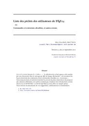
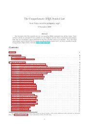
<strong>ChemFig</strong><br />
v1.1a<br />
23 february 2015<br />
Christian Tellechea<br />
A T E X package for drawing molecules<br />
OH<br />
HO<br />
OH<br />
CH 3<br />
OCH 3<br />
O<br />
CH 3<br />
HN<br />
O<br />
O<br />
O<br />
OH<br />
O<br />
CH 3<br />
O<br />
O<br />
O<br />
O<br />
CH 3<br />
Taxotere<br />
R ′<br />
N<br />
OH<br />
R<br />
N<br />
H ⊕ R ′ R<br />
⊕<br />
OH 2<br />
−H 2O<br />
⎡<br />
R ′<br />
⎢<br />
⎣<br />
R ′<br />
N<br />
⊕<br />
C R ⎤ ⎥ ⎥⎥⎦ H 2O<br />
⊕<br />
N C R<br />
R ′ N R<br />
⊕<br />
OH 2 OH<br />
−H ⊕ R ′ N R<br />
O<br />
R ′ N<br />
H<br />
R<br />
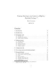
The Beckmann rearrangement
<strong>ChemFig</strong><br />
CONTENTS<br />
Contents<br />
I Introduction 3<br />
1 Foreword 3<br />
2 New in v1.1 4<br />
3 Presenting <strong>ChemFig</strong> 4<br />
II Operation of <strong>ChemFig</strong> 5<br />
1 Groups of atoms 5<br />
2 Different types of bonds 5<br />
3 Bond angle 7<br />
3.1 Predefined angles . . . . . . . . . . . . . . . . . . . . . . . . . . . . . . . . . . . . . . . . . . . . . 7<br />
3.2 Absolute angles . . . . . . . . . . . . . . . . . . . . . . . . . . . . . . . . . . . . . . . . . . . . . . 7<br />
3.3 Relative angles . . . . . . . . . . . . . . . . . . . . . . . . . . . . . . . . . . . . . . . . . . . . . . . 8<br />
4 Length of a bond 8<br />
5 Departure and arrival atoms 9<br />
6 Customization of bonds 10<br />
7 Default values 10<br />
8 Branches 11<br />
8.1 Principle . . . . . . . . . . . . . . . . . . . . . . . . . . . . . . . . . . . . . . . . . . . . . . . . . . 11<br />
8.2 Nesting . . . . . . . . . . . . . . . . . . . . . . . . . . . . . . . . . . . . . . . . . . . . . . . . . . . 12<br />
8.3 Method . . . . . . . . . . . . . . . . . . . . . . . . . . . . . . . . . . . . . . . . . . . . . . . . . . . 12<br />
9 Connecting distant atoms 13<br />
10 Rings 14<br />
10.1 Syntax . . . . . . . . . . . . . . . . . . . . . . . . . . . . . . . . . . . . . . . . . . . . . . . . . . . 14<br />
10.2 Angular position . . . . . . . . . . . . . . . . . . . . . . . . . . . . . . . . . . . . . . . . . . . . . . 15<br />
10.2.1 At the start . . . . . . . . . . . . . . . . . . . . . . . . . . . . . . . . . . . . . . . . . . . . 15<br />
10.2.2 After a bond . . . . . . . . . . . . . . . . . . . . . . . . . . . . . . . . . . . . . . . . . . . . 16<br />
10.3 Branches on a ring . . . . . . . . . . . . . . . . . . . . . . . . . . . . . . . . . . . . . . . . . . . . . 16<br />
10.4 Nested rings . . . . . . . . . . . . . . . . . . . . . . . . . . . . . . . . . . . . . . . . . . . . . . . . 17<br />
10.5 Rings and groups of atoms . . . . . . . . . . . . . . . . . . . . . . . . . . . . . . . . . . . . . . . . 18<br />
11 Representing electron movements 18<br />
11.1 Mesomeric effects . . . . . . . . . . . . . . . . . . . . . . . . . . . . . . . . . . . . . . . . . . . . . 19<br />
11.2 Reaction mechanisms . . . . . . . . . . . . . . . . . . . . . . . . . . . . . . . . . . . . . . . . . . . 20<br />
12 Writing a name under a molecule 21<br />
III Advanced usage 23<br />
1 Separating atoms 23<br />
2 Displaying atoms 23<br />
LATEXed by Christian Tellechea, the February 23, 2015. 1
<strong>ChemFig</strong><br />
CONTENTS<br />
3 Optional arguments 24<br />
4 Vertical alignment 25<br />
5 Shifted double bonds 26<br />
6 Delocalized double bonds 27<br />
7 Saving a sub-molecule 27<br />
8 Decorations 28<br />
8.1 Lewis diagrams . . . . . . . . . . . . . . . . . . . . . . . . . . . . . . . . . . . . . . . . . . . . . . 28<br />
8.2 Stacking characters . . . . . . . . . . . . . . . . . . . . . . . . . . . . . . . . . . . . . . . . . . . . 30<br />
8.3 Chemical reactions . . . . . . . . . . . . . . . . . . . . . . . . . . . . . . . . . . . . . . . . . . . . 31<br />
9 Using \chemfig in the tikzpicture environment 32<br />
10 Beyond chemistry 32<br />
11 Annotated examples 33<br />
11.1 Ethanal . . . . . . . . . . . . . . . . . . . . . . . . . . . . . . . . . . . . . . . . . . . . . . . . . . . 34<br />
11.2 2-amino-4-oxohexanoic acid . . . . . . . . . . . . . . . . . . . . . . . . . . . . . . . . . . . . . . . 34<br />
11.2.1 Absolute angles . . . . . . . . . . . . . . . . . . . . . . . . . . . . . . . . . . . . . . . . . . 34<br />
11.2.2 Relative angles . . . . . . . . . . . . . . . . . . . . . . . . . . . . . . . . . . . . . . . . . . 35<br />
11.2.3 Ring . . . . . . . . . . . . . . . . . . . . . . . . . . . . . . . . . . . . . . . . . . . . . . . . 35<br />
11.2.4 Nested rings . . . . . . . . . . . . . . . . . . . . . . . . . . . . . . . . . . . . . . . . . . . . 35<br />
11.3 Glucose . . . . . . . . . . . . . . . . . . . . . . . . . . . . . . . . . . . . . . . . . . . . . . . . . . . 36<br />
11.3.1 Skeleton diagram . . . . . . . . . . . . . . . . . . . . . . . . . . . . . . . . . . . . . . . . . 36<br />
11.3.2 Fisher projection . . . . . . . . . . . . . . . . . . . . . . . . . . . . . . . . . . . . . . . . . 36<br />
11.3.3 “Chair” representation . . . . . . . . . . . . . . . . . . . . . . . . . . . . . . . . . . . . . . 37<br />
11.3.4 Haworth projection . . . . . . . . . . . . . . . . . . . . . . . . . . . . . . . . . . . . . . . . 38<br />
11.4 Adrenaline . . . . . . . . . . . . . . . . . . . . . . . . . . . . . . . . . . . . . . . . . . . . . . . . . 38<br />
11.4.1 Using one ring . . . . . . . . . . . . . . . . . . . . . . . . . . . . . . . . . . . . . . . . . . 38<br />
11.4.2 Using two rings . . . . . . . . . . . . . . . . . . . . . . . . . . . . . . . . . . . . . . . . . . 39<br />
11.5 Guanine . . . . . . . . . . . . . . . . . . . . . . . . . . . . . . . . . . . . . . . . . . . . . . . . . . 40<br />
12 How to ... 41<br />
12.1 Write a colored atom . . . . . . . . . . . . . . . . . . . . . . . . . . . . . . . . . . . . . . . . . . . 41<br />
12.2 Add a superscript without modifying a bond . . . . . . . . . . . . . . . . . . . . . . . . . . . . . . 42<br />
12.3 Draw a curve bond . . . . . . . . . . . . . . . . . . . . . . . . . . . . . . . . . . . . . . . . . . . . 42<br />
12.4 Modify the size of a molecule . . . . . . . . . . . . . . . . . . . . . . . . . . . . . . . . . . . . . . . 43<br />
12.5 Draw a ploymer element . . . . . . . . . . . . . . . . . . . . . . . . . . . . . . . . . . . . . . . . . 43<br />
12.6 Draw the symmetrical of a molecule . . . . . . . . . . . . . . . . . . . . . . . . . . . . . . . . . . . 44<br />
12.7 Add text above bonds and arc to angles . . . . . . . . . . . . . . . . . . . . . . . . . . . . . . . . . 45<br />
12.8 Schéma de Lewis à l’angle près . . . . . . . . . . . . . . . . . . . . . . . . . . . . . . . . . . . . . . 45<br />
IV Reaction schemes 47<br />
1 Overview 47<br />
2 Arrow types 48<br />
3 Arrows features 48<br />
4 Compounds names 49<br />
5 Anchoring 49<br />
6 Compounds style 51<br />
LATEXed by Christian Tellechea, the February 23, 2015. 2
<strong>ChemFig</strong> 1 FOREWORD<br />
7 Branching 52<br />
8 Subscheme 52<br />
9 Arrows optional arguments 55<br />
10 Arrows customization 57<br />
10.1 First arrow . . . . . . . . . . . . . . . . . . . . . . . . . . . . . . . . . . . . . . . . . . . . . . . . . 57<br />
10.2 Curved arrow . . . . . . . . . . . . . . . . . . . . . . . . . . . . . . . . . . . . . . . . . . . . . . . 58<br />
11 The \merge command 59<br />
12 The + sign 61<br />
V List of commands 64<br />
VI Gallery 66<br />
Index 82<br />
PART I<br />
1 Foreword<br />
Introduction<br />
This package has seen the light of day thanks to the assistance of Christophe Casseau, who had the idea after<br />
being confronted with the complexity of the syntax of the ppchtex package.<br />
Throughout the writing of the code, he helped me find interesting features. He always encouraged me to write<br />
more advanced features even though I was sometimes (nearly always?) reluctant; if <strong>ChemFig</strong> has the features it<br />
does, it is in large part thanks to him. I thank him as well for his testing of beta versions of this package, and for<br />
his contributions to the writing of this manual.<br />
Experience shows that is it has been difficult to combine drawing of molecules with the typographic<br />
quality of a program like L A TEX, leaving little choice for the user who wishes to have a vector format<br />
for these drawings. After having abandoned the ppchtex package (developed for conTEXt and available<br />
under L A TEX) because of the complexity of its syntax, I turned to the world of programs outside L A TEX.<br />
The difficulty in this case is finding a compromise between quality and price. After many unsuccessful<br />
attempts I found the only option was a new package, and I would like to thank Christian Tellechea for<br />
bringing it to life. To meet my requirements, <strong>ChemFig</strong> needed to be easy to use but still have advanced<br />
features, something well nigh impossible. Yet he was able to put together a very flexible TEX code which<br />
makes it a pleasure for me to write my molecules. I hope it will be the same for you readers looking for a<br />
package useful in the field of chemistry.<br />
Christophe Casseau<br />
Finally, I wish to warmly thank Theo Hopman and more recently Nikola Castillo for offering to translate this<br />
manual into English.<br />
LATEXed by Christian Tellechea, the February 23, 2015. 3
<strong>ChemFig</strong> 3 PRESENTING <strong>ChemFig</strong><br />
2 New in v1.1<br />
For those who find it “ugly 1 ”, it is now possible to join simple bonds with a slightly increased compilation time. The<br />
macro \enablebondjoin enables this feature and \disablebondjoin disables it (better behaviour, set by default).<br />
\setbondstyle{line width=3pt}<br />
\chemfig{-[1]-[7]} and<br />
\enablebondjoin\chemfig{-[1]-[7]}\disablefixedbondlength<br />
Bond join<br />
When a star follows the macro \ chemfig*, the bonds have a fixed length and therefore, the distance between<br />
center to center atoms becomes variable. The macro \enablefixedbondlength makes this behavior valid for all<br />
macros (starred or not) while \disablefixedbondlength goes back to the default behavior.<br />
\chemfig{Cl-Cl}\par<br />
\chemfig*{Cl-Cl}<br />
Fixed length<br />
Cl<br />
Cl<br />
Cl<br />
Cl<br />
and<br />
3 Presenting <strong>ChemFig</strong><br />
To use this package, start by adding the following code to the preamble:<br />
• \input chemfig.tex with εTEX;<br />
• \usepackage{chemfig} with L A TEX;<br />
• \usemodule[chemfig] with ConTEXt.<br />
In all cases, the tikz package, if not loaded before, is loaded by <strong>ChemFig</strong>.<br />
The most important command for drawing molecules is \chemfig{}. The argument code is a set of<br />
characters describing the structure of the molecule according to the rules which are described in this manual.<br />
Care has been taken to make it possible to draw the greatest possible number of molecular configurations, while<br />
maintaining a simple, flexible, and intuitive syntax. Despite this, the which describes the 2D structure of<br />
the molecule increases in complexity in proportion to that of the molecule being drawn.<br />
The command \chemfig draws a molecule using the commands provided by the tikz package, placed inside a<br />
tikzpicture environment. The choice of tikz implies that:<br />
• the user has a choice of compilation method: pdfL A TEX can be used equally well in dvi mode (tex −→<br />
dvi −→ ps −→ pdf) or in pdf mode (tex −→ pdf). In effect tikz, via the underlying pgf, gives identical<br />
graphical results in the two modes;<br />
• the bounding box is automatically calculated by tikz and the user need not worry about any overlap with<br />
the text. However, care must be taken with alignment when the molecule is drawn in a paragraph. In the<br />
O<br />
following example, we have drawn the bounding box for the molecule: H 3 C<br />
always places the first atom of the molecule on the baseline of the preceding code.<br />
C<br />
OH<br />
. <strong>ChemFig</strong><br />
1 see http://tex.stackexchange.com/questions/161796/ugly-bond-joints-in-chemfig<br />
LATEXed by Christian Tellechea, the February 23, 2015. 4
<strong>ChemFig</strong> 2 DIFFERENT TYPES OF BONDS<br />
PART II<br />
Operation of <strong>ChemFig</strong><br />
This part is devoted to describing the most common features of <strong>ChemFig</strong>. The user will find here explanations<br />
sufficient to draw most molecules. The presentation of features is done from a theoretical angle, and the goal of<br />
this part is not to draw real molecules but to give the user a formal description of the functionality of <strong>ChemFig</strong>.<br />
The “Advanced usage”, page 23, will be more practical and will illustrate advanced features for the most demanding<br />
uses. It will also highlight methods of building real molecules, page 33. Finally, the last part will give examples of<br />
molecules and the code used to draw them.<br />
1 Groups of atoms<br />
Drawing a molecule consists inherently of connecting groups of atoms with lines. Thus, in the molecule O O,<br />
there are two groups of atoms, each consisting of a single atom “O”.<br />
However, in this molecule<br />
H 3 C<br />
OH<br />
there are four groups of atoms: “H 3 C”, “C”, “O” and “OH”. For reasons which we shall see later, <strong>ChemFig</strong> splits<br />
each group into single atoms. Each atom extends up to the next capital letter or one of these special characters: -<br />
= ~ ( ! * < > @. <strong>ChemFig</strong> ignores all characters inside braces when splitting groups into atoms.<br />
Therefore the first group of atoms “H 3 C” is split into two atoms: H 3 and C . In terms of chemistry, of course,<br />
these are not real atoms; H 3 , for example, consists of three hydrogen atoms. In what follows the word atom refers<br />
to <strong>ChemFig</strong>’s definition. Thus <strong>ChemFig</strong> sees the preceding molecule as follows:<br />
H 3 C<br />
A space is ignored when at the begining of a group of atoms.<br />
C<br />
C<br />
O<br />
O<br />
O H<br />
2 Different types of bonds<br />
For <strong>ChemFig</strong>, bonds between two atoms are one of nine types, represented by the characters -, =, ~, >, :,<br />
| and B} A B right Cram, plain<br />
5 \chemfig{A:B} A B right Cram, dashed<br />
7 \chemfig{A|B} A B right Cram, hollow<br />
9 \chemfig{A
<strong>ChemFig</strong> 2 DIFFERENT TYPES OF BONDS<br />
The command \setdoublesep{} adjusts the spacing between the lines in double or triple bonds. This<br />
spacing is 2pt by default.<br />
We must understand that when a bond is made between two atoms, these atoms are contained within invisible<br />
rectangular boxes. The centres of these two rectangles are separated by an adjustable distance ∆ called the<br />
“interatomic distance”. Furthermore, bonds do not connect to the exact edges of the rectangles: a length δ, also<br />
adjustable, separates the edges of the rectangles and the beginning and end of the bond line. The rectangular<br />
boxes are made visible in the diagram below to help understanding.<br />
A<br />
δ<br />
∆<br />
δ<br />
B<br />
The macro \setatomsep{} adjusts the interatomic distance ∆. If the is empty, it takes<br />
the default value of 3em. This command, like all other settings commands, affects all the following molecules.<br />
\setatomsep{2em}\chemfig{A-B}\par<br />
\setatomsep{50pt}\chemfig{A-B}<br />
Interatomic distance<br />
The command \setbondoffset{} sets the spacing δ between the bond line and the atom. If the<br />
is empty, δ takes the default value of 2pt.<br />
\setbondoffset{0pt}\chemfig{A-B}\par<br />
\setbondoffset{5pt}\chemfig{A-B}<br />
Trimming bonds<br />
If one bond is followed immediately by another, then <strong>ChemFig</strong> inserts an empty group {}. Around this empty<br />
group the separation δ is zero:<br />
Empty groups<br />
\chemfig{A-B=-=C} A B C<br />
A<br />
A<br />
A<br />
A<br />
B<br />
B<br />
B<br />
B<br />
The \setbondstyle{} command sets the style for all the bonds drawn thereafter. The <br />
is empty by default. To custom a single bond, see page 10.<br />
\setbondstyle{line width=1pt,red}<br />
\chemfig{A-B=C>|D:F}<br />
Style of bonds<br />
A B C D E F<br />
The spacing δ for just one bond can be specified with the character #. This character must be placed immediately<br />
after the bond symbol and has one required argument between parentheses of the form “#(,)”,<br />
where is the spacing δ at the beginning of the bond and is the that at the end. If is omitted,<br />
the spacing at the end of the bond takes the value of δ in effect at that time. One can see in the example how the<br />
shortening, set to 4pt to be more visible, is nullified for the bond arriving at “B”, then for the one leaving “B”, and<br />
finally for both:<br />
\setbondoffset{4pt}<br />
\chemfig{A-B-C}\par<br />
\chemfig{A-#(,0pt)B-C}\par<br />
\chemfig{A-B-#(0pt)C}\par<br />
\chemfig{A-#(,0pt)B-#(0pt)C}<br />
Fine adjustment of bond shortening<br />
A B C<br />
A B C<br />
A B C<br />
A B C<br />
By default, all atoms within groups of atoms are typeset in math mode (spaces are ignored). They may therefore<br />
contain math mode specific commands such as subscripts or superscripts 2 :<br />
Math mode<br />
\chemfig{A_1B^2-C _ 3 ^ 4} A 1 B 2 C 4 3<br />
2 There is a problem with the placement of groups of atoms containing exponents or subscripts. See page 25.<br />
LATEXed by Christian Tellechea, the February 23, 2015. 6
<strong>ChemFig</strong> 3 BOND ANGLE<br />
There are settings specifically for Cram bonds. This syntax is used:<br />
\setcrambond{}{}{}<br />
Any empty argument takes its default value. The three arguments are:<br />
• is the size of the base of the triangle, and is 1.5pt by default;<br />
• is the thickness of the dots, and is 1pt by default;<br />
• is the spacing between the dots, and is 2pt by default.<br />
Here is an example where the three dimensions are changed:<br />
Modified Cram bonds<br />
\setcrambond{10pt}{0.4pt}{1pt}<br />
\chemfig{A>B>:C>|D}<br />
A B C D<br />
3 Bond angle<br />
Each bond takes an optional argument in brackets. This optional argument can adjust every aspect of a bond,<br />
and consists of five optional fields separated by commas. The first of these fields defines the bond angle. Angles<br />
increase counterclockwise, and are relative to the horizontal. If the angle field is empty, the angle takes its default<br />
value of 0 ◦ . We will see later how to change this default.<br />
There are several ways of specifying the bond angle.<br />
3.1 Predefined angles<br />
When the angle field contains an integer, this represents the angle the bond makes relative to the horizontal, in<br />
multiples of 45 ◦ . For example, [0] specifies an angle of 0 ◦ , [1] is 45 ◦ , and so on up to [7] which specifies an angle<br />
of 315 ◦ . The integer may lie outside the interval [0, 7], in which case the angle is reduced to the interval [0, 360).<br />
Predefined angles<br />
D<br />
\chemfig{A-B-[1]C-[3]-D-[7]E-[6]F}<br />
C<br />
E<br />
A<br />
B<br />
F<br />
These angles remain valid if the atoms are empty, and this is the case for all the features we will see below:<br />
Predefined angles with empty groups<br />
\chemfig{--[1]-[3]--[7]-[6]}<br />
3.2 Absolute angles<br />
If one wishes to specify an angle in degrees relative to the horizontal, then the optional angle field must take this<br />
form: [:]. If necessary, the is reduced to the interval [0, 360):<br />
Absolute angles<br />
E<br />
\chemfig{A-[:30]B=[:-75]C-[:10]D-[:90]>|[:60]-[:-20]E-[:0]~[:-75]F}<br />
A<br />
B<br />
C<br />
D<br />
F<br />
LATEXed by Christian Tellechea, the February 23, 2015. 7
<strong>ChemFig</strong> 4 LENGTH OF A BOND<br />
3.3 Relative angles<br />
It is often useful to specify a bond angle relative to the preceding bond. This syntax must be then be used:<br />
[::]. The sign of the can be omitted if it is a +.<br />
Here is a molecule where the first bond has an absolute angle of −5 ◦ , and the rest of the bond angles are<br />
incremented by 20 ◦ :<br />
Result of relative angles<br />
C<br />
\chemfig{A-[:-5]-[::+20]-[::20]B-[::+20]-[::20]C-[::20]}<br />
One can “break” a chain of relative angles by putting an absolute or predefined angle where desired. Here, atom<br />
“B” is followed by a bond at an absolute angle of 315 ◦ .<br />
\chemfig{A-[:-5]-[::20]-[::20]B-[7]-[::20]C-[::20]}<br />
Result of relative angles followed by absolute<br />
A<br />
A<br />
B<br />
B<br />
C<br />
4 Length of a bond<br />
Rather than speaking of length of a bond, we should use the term interatomic spacing. If effect, only the interatomic<br />
spacing is adjustable with \setatomsep as we have seen on page 6. Once this parameter is set, the length of a<br />
bond depends on the content of atoms and, to a lesser extent, the angle the bond makes with the horizontal. It<br />
should be obvious that two “slimmer” atoms will have larger edge separations than two which are larger. This can<br />
be seen easily in the following example where an “I” atom is narrower than an “M” atom, which means that the<br />
bond between the “I” atoms is longer than that between the “M” atoms:<br />
\chemfig{I-I}\par<br />
\chemfig{M-M}<br />
Influence of the size of atoms<br />
This aspect of the size of atoms becomes particularly acute when the atom involves subscripts or superscripts. In<br />
this example, the bond is extremely short, to the point of confusion with a negative sign −:<br />
Too-short bond<br />
\chemfig{A^{++}_{2}-B^{-}_3} A ++<br />
2 B − 3<br />
It is important to note that the exponent - is put inside braces. If this were not done, <strong>ChemFig</strong> would stop the<br />
atom on this character, which is a bond character. The atom would then be “B^”, which would lead to unexpected<br />
results.<br />
It is possible to change the behavior of <strong>ChemFig</strong> about the interatomic spacing. Indeed, when the \chemfig<br />
macro is immediately followed by a star, the macro \setatomsep{} no longer defines the distance<br />
between the centers of atoms, denoted ∆, but length of the bonds. Consequently, the bonds have fixed lengths<br />
while the distance between the centers of the atoms is variable and depends on their size. Here is the diagram on<br />
page 6 and what becomes with the macro \ chemfig*:<br />
I<br />
M<br />
I<br />
M<br />
macro \chemfig<br />
macro \chemfig*<br />
A<br />
δ<br />
∆<br />
δ<br />
B<br />
A<br />
δ<br />
∆<br />
δ<br />
B<br />
LATEXed by Christian Tellechea, the February 23, 2015. 8
<strong>ChemFig</strong> 5 DEPARTURE AND ARRIVAL ATOMS<br />
In rings, even with starred \chemfig*, the default behaviour is restored in order to draw regular polygons.<br />
Fixed length bonds<br />
\chemfig{Cl-Cl}\par<br />
\chemfig*{Cl-Cl}<br />
The macro \enablefixedbondlength enables the “fixed bond length behaviour”, even for non starred \chemfig<br />
while \disablefixedbondlength goes back to the default behaviour (fixed interatomic distance).<br />
Especially with the default behavior, to avoid too short bonds, it is sometimes necessary to increase (or perhaps<br />
reduce) the interatomic distance. For this, the optional argument to bonds is actually made up of several commaseparated<br />
fields. As we have seen, the first field specifies the angle. The second field, if it is not empty, is a<br />
coefficient which multiplies the default interatomic distance ∆. Thus, writing -[,2] asks that this bond have the<br />
default angle (first field is empty) and that the atoms it connects be separated by twice the default distance.<br />
Modified bond length<br />
\chemfig{A^{++}_{2}-[,2]B^{-}_3}\par<br />
\chemfig{A-B-[,2]C=[,0.5]D}\par<br />
\chemfig{-=[,1.5]-[,0.75]=[:-20,2]}<br />
Cl<br />
Cl<br />
Cl<br />
Cl<br />
A ++<br />
2 B − 3<br />
A B C D<br />
We can change the size of molecules by altering the font size or the argument of \setatomsep, possibly on both 3 ,<br />
being careful to confine these changes within a group if we want to limit the scope:<br />
How to modify the size of molecule<br />
O<br />
\normalsize \chemfig{H-[:30]O-[:-30]H}\par<br />
\setatomsep{2.5em}\chemfig{H-[:30]O-[:-30]H}\par<br />
\small<br />
\chemfig{H-[:30]O-[:-30]H}\par<br />
\footnotesize \chemfig{H-[:30]O-[:-30]H}\par<br />
\scriptsize \chemfig{H-[:30]O-[:-30]H}\par<br />
\tiny<br />
\chemfig{H-[:30]O-[:-30]H}<br />
H<br />
H<br />
H<br />
H<br />
H<br />
O<br />
H<br />
O<br />
H<br />
O<br />
H<br />
O<br />
H H<br />
O<br />
H H<br />
5 Departure and arrival atoms<br />
A group of atoms can contain several atoms. Suppose we want to connect the group “ABCD” to the group<br />
“EFG” with a bond. <strong>ChemFig</strong> calculates which atom of the first group and which of the second group are to be<br />
connected by looking at the angle of bond relative to the horizontal. If the angle is between (but not including)<br />
−90 ◦ and 90 ◦ (modulo 360 ◦ ) then the bond is made between the last atom of the first group and the first atom of<br />
the second group. In all other cases, the bond is made between the first atom of the first group and the last atom<br />
of the second group.<br />
Here are some examples where the bond is in the interval (−90, 90), and where the bond is made between D and<br />
E:<br />
Default atom connections<br />
\chemfig{ABCD-[:75]EFG}\quad<br />
\chemfig{ABCD-[:-85]EFG}\quad<br />
\chemfig{ABCD-[1]EFG}<br />
ABCD<br />
EFG<br />
ABCD<br />
EFG<br />
ABCD<br />
In the following examples, the angles are in the interval [90, 270] and so the bond is made between A and G:<br />
Default atom connections<br />
\chemfig{ABCD-[:100]EFG}\quad<br />
\chemfig{ABCD-[:-110]EFG}\quad<br />
\chemfig{ABCD-[5]EFG}<br />
3 You can also use the second optional argument of \chemfig, see page 24.<br />
EFG<br />
ABCD<br />
EFG<br />
ABCD<br />
EFG<br />
ABCD<br />
EFG<br />
LATEXed by Christian Tellechea, the February 23, 2015. 9
<strong>ChemFig</strong> 7 DEFAULT VALUES<br />
One may sometimes want the bond partners to be atoms other than those determined by <strong>ChemFig</strong>. The departure<br />
and arrival atoms can be set with the optional bond argument by writing:<br />
[,,,]<br />
where and are the numbers of the desired departure and arrival atoms. These atoms<br />
must exist, otherwise an error message will be given.<br />
\chemfig{ABCD-[:75,,2,3]EFG}\qquad<br />
\chemfig{ABCD-[:75,,,2]EFG}\qquad<br />
\chemfig{ABCD-[:75,,3,2]EFG}<br />
Specified atom connections<br />
EFG<br />
ABCD<br />
ABCD<br />
EFG<br />
EFG<br />
ABCD<br />
6 Customization of bonds<br />
There is a fifth and last optional argument for bonds which is found after the fourth comma:<br />
[,,,,]<br />
This is passed directly to tikz when the bond is drawn. There one can put characteristics such as<br />
colour (red), dash type (dash pattern=on 2pt off 2pt), thickness (line width=2pt), or even decoration if the<br />
tikz decoration library has been loaded. A bond can be made invisible by writing “draw=none”. To set several<br />
attributes, the syntax of tikz is used, separating them by a comma:<br />
\chemfig{A-[,,,,red]B}\par<br />
\chemfig{A-[,,,,dash pattern=on 2pt off 2pt]B}\par<br />
\chemfig{A-[,,,,line width=2pt]B}\par<br />
\chemfig{A-[,,,,red,line width=2pt]B}<br />
Passing tikz code<br />
Numerous tikz decoration libraries are available. For example, one can use the “pathmorphing” library by putting<br />
\usetikzlibrary{decorations.pathmorphing} in the preamble in order to draw wavy bonds:<br />
\chemfig{A-[,3,,,decorate,decoration=snake]B} A B<br />
Cram bonds ignore thickness and dash settings.<br />
Wavy bonds<br />
A<br />
A<br />
A<br />
A<br />
B<br />
B<br />
B<br />
B<br />
7 Default values<br />
At the beginning of each molecule, the default values for the optional arguments are initialized. They are:<br />
• 0 ◦ for the bond angle;<br />
• 1 for the length multiplication coefficient;<br />
• for the numbers of the departure and arrival atoms, which lets <strong>ChemFig</strong> calculate these based<br />
on the bond angle;<br />
• for the parameters passed to tikz.<br />
These default values can be changed for the whole molecule by beginning the molecule code with<br />
[,,,,
<strong>ChemFig</strong> 8 BRANCHES<br />
If something odd like [1,1.5,2,2,red,thick] is written, then unless otherwise indicated all the bonds will have<br />
an angle of 45 ◦ , the interatomic distances will be 1.5 times the default distance, the bonds will begin and end on<br />
the second atom of each group, and the bonds will be red and thick:<br />
Default values<br />
GHI<br />
\chemfig{[1,1.5,2,2,red,thick]ABC-DEF=GHI}<br />
DEF<br />
ABC<br />
8 Branches<br />
8.1 Principle<br />
Up to now, all the molecules have been linear, which is rare. A sub-molecule can be attached to an atom by<br />
following the atom with in parentheses. This is the code of the submolecule which will be attached<br />
to the atom.<br />
In this example, the sub-molecule “-[1]W-X” will be attached to atom “B”:<br />
\chemfig{A-B(-[1]W-X)-C}<br />
A branch<br />
There can be several sub-molecules which are to be attached to the same atom. Just have several parentheses<br />
containing the code for each sub-molecule:<br />
Multiple branches<br />
A<br />
B<br />
W<br />
W<br />
C<br />
X<br />
X<br />
\chemfig{A-B(-[1]W-X)(-[6]Y-[7]Z)-C}<br />
A<br />
B<br />
C<br />
Y<br />
Z<br />
The code of each sub-molecule can define its own default values, which will be valid throughout the whole<br />
sub-molecule. Here a sub-molecule “[:60]-D-E” is attached to atom “B”, with a default angle of 60 ◦ absolute. A<br />
second sub-molecule “[::-60,1.5]-X-Y” is attached to “B” with a default bond angle 60 ◦ less than that of the<br />
preceding bond (which will be the one between “A” and “B”) and with an interatomic distance 1.5 times the default<br />
value:<br />
Default values in branches<br />
D<br />
E<br />
\chemfig{A-B([:60]-D-E)([::-30,1.5]-X-Y)-C}<br />
A<br />
B<br />
C<br />
X<br />
Y<br />
Observe what happens if, at the beginning of the main molecule, one writes “[:-45]”:<br />
LATEXed by Christian Tellechea, the February 23, 2015. 11
<strong>ChemFig</strong> 8 BRANCHES<br />
Effect of the default bond angle<br />
E<br />
A<br />
D<br />
B<br />
\chemfig{[:-45]A-B([:60]-D-E)([::-30,1.5]-X-Y)-C}<br />
C<br />
X<br />
Y<br />
We see that the angle between the bond B-C and the bond B-X stays at 30 ◦ because it is a relative angle for the<br />
sub-molecule “-X-Y”. By contrast, the branch “-D-E” stays inclined at 60 ◦ to the horizontal, and does not follow<br />
the rotation given by the −45 ◦ angle at the beginning; this is expected because “-D-E” has an absolute angle. It is<br />
essential that all the angles be relative in order to rotate the whole molecule.<br />
8.2 Nesting<br />
Sub-molecules may be nested, and the rules seen in the preceding paragraphs stay in force:<br />
Nested branches<br />
Z<br />
Y<br />
\chemfig{A-B([1]-X([2]-Z)-Y)(-[7]D)-C}<br />
A<br />
B<br />
X<br />
D<br />
C<br />
8.3 Method<br />
O<br />
Suppose now that we want to draw an acid anhydride molecule: R<br />
C<br />
O<br />
R<br />
C<br />
O<br />
The best way to get this is to find the longest chain. Here, for example, we can draw the chain R-C-O-C-R taking<br />
into account angles and using only relative angles:<br />
Acid anhydride structure<br />
R<br />
C<br />
\chemfig{R-C-[::-60]O-[::-60]C-[::-60]R}<br />
O<br />
R<br />
C<br />
To this structure we just have to add two “=O” sub-molecules to each of the carbon atoms:<br />
LATEXed by Christian Tellechea, the February 23, 2015. 12
<strong>ChemFig</strong> 9 CONNECTING DISTANT ATOMS<br />
Acid anhydride<br />
O<br />
R<br />
C<br />
\chemfig{R-C(=[::+60]O)-[::-60]O-[::-60]C(=[::+60]O)-[::-60]R}<br />
O<br />
R<br />
C<br />
O<br />
Because we used only relative angles, we can rotate this molecule by giving a default angle of e.g. 75 ◦ :<br />
Rotation of a molecule<br />
O<br />
O<br />
C<br />
\chemfig{[:75]R-C(=[::+60]O)-[::-60]O-[::-60]C(=[::+60]O)-[::-60]R}<br />
O<br />
C<br />
R<br />
R<br />
9 Connecting distant atoms<br />
We have seen how to connect atoms which are adjacent in the code. It is often necessary to connect atoms which<br />
are not next to each other in the code. Let’s call these particular bonds “distant bonds”.<br />
Let’s take this molecule:<br />
Branched structure<br />
W<br />
X<br />
\chemfig{A-B(-[1]W-X)(-[7]Y-Z)-C} A B<br />
C<br />
Y<br />
Z<br />
and suppose that we want to connect the atoms X and C. In this case, <strong>ChemFig</strong> allows a “hook” to be placed<br />
immediately after the atom of interest. The character used for a hook is “?” because of its similarity to a hook. So,<br />
if one writes X? then the atom X will have a hook. Later in the code, all atoms followed by a ? will be connected to<br />
X:<br />
Distant bond<br />
W<br />
X<br />
\chemfig{A-B(-[1]W-X?)(-[7]Y-Z)-C?} A B<br />
C<br />
Y<br />
Z<br />
We could connect other atoms to X by following them with ?. Here it’s the atoms C and Z:<br />
Several distant bonds<br />
W X<br />
\chemfig{A-B(-[1]W-X?)(-[7]Y-Z?)-C?} A B<br />
C<br />
Y<br />
Z<br />
Now imagine if we were to leave the distant bonds X-C and X-Zwhile adding another: A-W. We must therefore ask<br />
for two different hooks, one on A and the other on X. Fortunately the character ? has an optional argument:<br />
where each field takes its default value if it is empty:<br />
?[,,]<br />
• The is the name of the hook: all alphanumeric characters (a...z, A...Z, 0...9) are allowed 4 . The<br />
name is a by default. In the first occurrence of the hook with this name, only this field is used.<br />
4 This is not exactly right. Actually all the characters that can be put between \csname...\endcsname are allowed.<br />
LATEXed by Christian Tellechea, the February 23, 2015. 13
<strong>ChemFig</strong> 10 RINGS<br />
• specifies how the atom with the current occurrence of the named hook is to be bonded to the atom<br />
with the first occurrence of the hook. There are two ways this can be done. First, this field can be an<br />
integer representing the desired bond type: 1=single bond, 2=double bond, etc. (See the table on page 5 for<br />
the bond codes.)<br />
Second, the field can be one of the bond character codes, provided that this character is between braces.<br />
• will be passed directly to tikz as we have seen with regular bonds.<br />
Here is our molecule with the required distant bonds, then with the bond A-W and X-C customized:<br />
Multiple distant bonds<br />
W<br />
X<br />
A<br />
B<br />
C<br />
\chemfig{A?[a]-B(-[1]W?[a]-X?[b])(-[7]Y-Z?[b])-C?[b]}\par\medskip<br />
\chemfig{A?[a]-B(-[1]W?[a,2,red]-X?[b])(-[7]Y-<br />
Z?[b,1,{line width=2pt}])-C?[b,{>},blue]}<br />
Y<br />
W<br />
Z<br />
X<br />
A<br />
B<br />
C<br />
Y<br />
Z<br />
Several different hooks can be written after an atom. Suppose that in this unfinished pentagon, we wish to connect<br />
A-E, A-C and E-C:<br />
\chemfig{A-[:-72]B-C-[:72]D-[:144]E}<br />
An incomplete ring<br />
A<br />
E<br />
D<br />
B<br />
C<br />
Then we must do this:<br />
\chemfig{A?[a]-[:-72]B-C?[a]?[b]-[:72]D-[:144]E?[a]?[b]}<br />
Multiple distant bonds<br />
A<br />
E<br />
D<br />
B<br />
C<br />
10 Rings<br />
The preceding example shows how to draw a regular polygon, but the method used is tedious because the angles<br />
depend on the number of sides of the polygon.<br />
10.1 Syntax<br />
<strong>ChemFig</strong> can easily draw regular polygons. The idea is to attach a ring to an outside the ring with this<br />
syntax:<br />
*()<br />
is the number of sides of the polygon and the describes the bonds and groups of atoms which make<br />
up its edges and vertices. This code must begin with a bond because the atom is outside the ring.<br />
Here is a 5-ring, attached to the atom “A”:<br />
\chemfig{A*5(-B=C-D-E=)}<br />
5-ring<br />
E<br />
A<br />
D<br />
B<br />
C<br />
A ring can also be drawn with one, several, or all the groups of atoms empty, as is the case for diagrams outside<br />
rings:<br />
LATEXed by Christian Tellechea, the February 23, 2015. 14
<strong>ChemFig</strong> 10 RINGS<br />
5-ring with empty groups<br />
\chemfig{*5(-=--=)}<br />
A ring can be incomplete:<br />
Incomplete 5-ring<br />
D<br />
\chemfig{*5(-B=C-D)}<br />
C<br />
If a ring has a code which contains too many bonds and atom groups for the given number of vertices, all the<br />
bonds and groups over the maximum allowed are ignored:<br />
Truncated 5-ring<br />
\chemfig{A*5(-B=C-D-E=F-G=H-I)}<br />
It is possible to draw a circle or an arc in the inside of a ring. To do so, the following syntax is used:<br />
**[,,]()<br />
where each field of the optional argument takes its default value if it is empty:<br />
• and are the absolute angles of the start and finish of the arc. These default to 0 ◦ and<br />
360 ◦ respectively so that a circle is drawn by default;<br />
• is the code that will be passed to tikz for drawing the arc.<br />
Rings and arcs<br />
E<br />
A<br />
B<br />
D<br />
B<br />
C<br />
\chemfig{**6(------)}\quad<br />
\chemfig{**[30,330]5(-----)}\quad<br />
\chemfig{**[0,270,dash pattern=on 2pt off 2pt]4(----)}<br />
10.2 Angular position<br />
10.2.1 At the start<br />
As can be seen in the examples above, the rule is that the attachment atom “A” is always at the south-west of the<br />
ring. Furthermore, the ring is always constructed counterclockwise, and the last bond descends vertically onto<br />
the attachment atom:<br />
Angular position of rings<br />
\chemfig{A*4(-B-C-D-)}\qquad\chemfig{A*6(------)}<br />
D<br />
A<br />
C<br />
B<br />
A<br />
If this angular position is not convenient, it is possible to specify another angle using the optional argument at<br />
the beginning of the molecule. Here is a 6-cycle which has been rotated by +30 ◦ , by −30 ◦ , and lastly by +60 ◦ :<br />
Rotation of rings<br />
\chemfig{[:30]A*6(------)}\qquad<br />
\chemfig{[:-30]A*6(------)}\qquad<br />
\chemfig{[:60]A*6(------)}<br />
A A A<br />
LATEXed by Christian Tellechea, the February 23, 2015. 15
<strong>ChemFig</strong> 10 RINGS<br />
10.2.2 After a bond<br />
When a ring does not begin a molecule and one or more bonds have already been drawn, the default angular<br />
position changes: the ring is drawn is such a way that the bond ending on the attachment atom bisects the angle<br />
formed by the first and last sides of the ring.<br />
Here is a simple case:<br />
Bond ending on a ring<br />
\chemfig{A-B*5(-C-D-E-F-)} A B<br />
F<br />
C<br />
E<br />
D<br />
The rule remains valid, whatever the angle of the preceding bond:<br />
Bonds ending on a ring<br />
\chemfig{A-[:25]B*4(----)}\vskip5pt<br />
\chemfig{A=[:-30]*6(=-=-=-)}<br />
A<br />
A<br />
B<br />
10.3 Branches on a ring<br />
To have branches attached to the vertices of a ring, we use the syntax we have already seen:<br />
()<br />
where the is that of the sub-molecule and the is at the vertex. Unique to rings, the default angle of<br />
the sub-molecule is not 0 ◦ but is calculated so that it will bisect the sides leaving the vertex:<br />
\chemfig{X*6(-=-(-A-B=C)=-=-)}<br />
Branch on a ring<br />
A<br />
B<br />
C<br />
X<br />
A sub-molecule can be attached to the first vertex of a ring, just like the other vertices:<br />
Ring and branches<br />
F<br />
G<br />
\chemfig{*5((-A=B-C)-(-D-E)-(=)-(-F)-(-G=)-)}<br />
A<br />
C<br />
B<br />
D<br />
E<br />
If one wants the bond leaving a vertex not to be the bisector of its sides, one can tinker with the optional global<br />
parameter or the optional bond parameter:<br />
LATEXed by Christian Tellechea, the February 23, 2015. 16
<strong>ChemFig</strong> 10 RINGS<br />
Branches at specified angles<br />
B<br />
B<br />
B<br />
\chemfig{*5(---([:90]-A-B)--)}\qquad<br />
A<br />
A<br />
A<br />
\chemfig{*5(---(-[:90]A-B)--)}\qquad<br />
\chemfig{*5(---([::+0]-A-B)--)}<br />
It is worth noting that in the third example, where a relative angle of 0 ◦ was given, the bonds of the branch are<br />
drawn in line with the preceding bond in the ring. This is the rule on page 8 which specified that the reference<br />
angle was that of the bond last drawn.<br />
We can now connect together rings with bonds:<br />
Connected rings<br />
\chemfig{*6(--(-*5(----(-*4(----))-))----)}<br />
10.4 Nested rings<br />
To “glue” two rings together, the syntax is only slightly different: the vertex is specified where the other ring<br />
is going to start. Simply follow this vertex by the usual syntax for a ring. Here for example is a 5-ring which is<br />
attached to the second vertex of a 6-ring:<br />
Nested rings<br />
\chemfig{A*6(-B*5(----)=-=-=)}<br />
A<br />
B<br />
Note that the ring which is going to be attached to the main ring has an angular position such that two of the<br />
rings’ sides coincide. In addition, the 5-ring has only four bonds “----”. In effect, the fifth will be useless because<br />
it is the second side of the 6-ring, which has already been drawn.<br />
It is quite possible to glue multiple rings together:<br />
Multiple nested rings<br />
\chemfig{*5(--*6(-*4(-*5(----)--)----)---)}<br />
There is a case where a trick must be used. It can be seen in this example that the fourth side of the second 5-ring<br />
just passes through the centre of atom “E”.<br />
LATEXed by Christian Tellechea, the February 23, 2015. 17
<strong>ChemFig</strong> 11 REPRESENTING ELECTRON MOVEMENTS<br />
Flawed drawing<br />
F<br />
Z<br />
E<br />
\chemfig{A-B*5(-C-D*5(-X-Y-Z-)-E-F-)} A B<br />
Y<br />
D<br />
C X<br />
This is normal because the second 5-ring (which is attached to atom “D”) is drawn before <strong>ChemFig</strong> knows about<br />
atom “E”. In this case, it is necessary to use two hooks to draw the bond Z-E:<br />
Distant bond and ring<br />
\chemfig{A-B*5(-C-D*5(-X-Y-Z?)-E?-F-)} A B<br />
F<br />
C<br />
E<br />
D<br />
Z<br />
X<br />
Y<br />
We could also use a \phantom{E} at the last vertex of the 5-ring:<br />
Using \phantom<br />
\chemfig{A-B*5(-C-D*5(-X-Y-Z-\phantom{E})-E-F-)} A B<br />
F<br />
C<br />
E<br />
D<br />
Z<br />
X<br />
Y<br />
10.5 Rings and groups of atoms<br />
Some care must be taken with rings when one or more vertices are made up of groups of atoms:<br />
\chemfig{AB*5(-CDE-F-GH-I-)}<br />
Ring and groups of atoms<br />
In order for the ring to have a regular shape, it is necessary to override the <strong>ChemFig</strong> mechanism which<br />
automatically calculates the departure and arrival atoms of bonds. Here, C-F and F-G must be connected by using<br />
the optional argument of these bonds:<br />
\chemfig{AB*5(-CDE-[,,1]F-[,,,1]GH-I-)}<br />
Forced departure and arrival atoms<br />
AB<br />
I<br />
AB<br />
I<br />
GH<br />
CDE<br />
GH<br />
F<br />
CDE<br />
F<br />
11 Representing electron movements<br />
Starting with <strong>ChemFig</strong> version 0.3, we can represent the movement of electrons in mesomeric effects or reaction<br />
mechanisms. This is done by marking the departure and arrival points of the electron movement arrow using<br />
the syntax “@{}”. This syntax allows a tikz node to be placed and makes this node accessible outside<br />
the argument of the \chemfig command thanks to the “remember picture” option which is passed to all the<br />
“tikzpicture” environments. It is assumed that the viewer supports “picture remembering” and that the compilation<br />
is done twice.<br />
Two types of diagrams can arise, so we can ask for:<br />
• a zero size node on a bond using the syntax “@{,}” placed at the beginning of the optional<br />
argument of the relevant bond, without being followed by a comma if there is a first optional argument. In<br />
this case, the node takes the name “” and the , which must be between 0 and 1, determines<br />
where the node is located on the bond. If “@{}” is used, the is set to 0.5 by default, which<br />
means that the node is placed halfway along the bond;<br />
LATEXed by Christian Tellechea, the February 23, 2015. 18
<strong>ChemFig</strong> 11 REPRESENTING ELECTRON MOVEMENTS<br />
• a node on an atom using the syntax “@{}” immediately before the relevant atom. In this case, the<br />
node has exactly the same footprint as the atom, but may be empty and therefore have zero dimensions.<br />
Once the \chemfig command has drawn the molecule(s) and has placed the nodes with the syntax described<br />
above, we can connect these nodes to each other with tikz instructions. These instructions are placed in the<br />
argument of the command \chemmove 5 and has the following syntax if (for example) we need to connect a node<br />
named “” to the node named “”:<br />
\chemmove[]{\draw[]()();}<br />
The optional argument of the \chemmove command will be added to the argument of the tikzpicture<br />
environment in which the links between the nodes will be drawn. The and instructions<br />
are describe in detail in the documentation of the tikz package.<br />
11.1 Mesomeric effects<br />
To make these concepts concrete, let’s take the example of a mesomeric effect involving a double bond and<br />
non-bonding lone pair conjugate. Let’s begin with the possible delocalization of electrons from the double bond.<br />
We will place a node named “db” (double bond) in the middle of the double bond and a node named “a1” on the<br />
end of the double bond.<br />
Mesomeric effect 1<br />
\chemfig{@{a1}=_[@{db}::30]-[::-60]\lewis{2,X}}<br />
\chemrel{}<br />
\chemfig{\chemabove{\vphantom{X}}{\ominus}-[::30]=_[::-60]<br />
\chemabove{X}{\scriptstyle\oplus}}<br />
\chemmove{\draw[->](db).. controls +(80:8mm) and +(145:8mm).. (a1);}<br />
As noted above, there is no comma after the node placed in the optional arguments of a bond; we write<br />
“=_[@{db}::30]” and not “=_[@{db},::30]” as one might be tempted to do.<br />
To link the nodes “db” and “a1” we have used the following syntax:<br />
\chemmove{\draw[->](db)..controls +(80:8mm) and +(145:8mm)..(a1);}<br />
In this example we ask for an arrow ([->]) and we use two control points 6 . These will be located using polar<br />
coordinates at 80 ◦ and 8 mm from “db” for the first and at 145 ◦ and 8 mm from “a1” for the second. Though this<br />
syntax may seem complicated at first reading, one need not be alarmed because its use will usually be a matter of<br />
copying and pasting. Only the names and coordinates of the control points need be changed, as can be verified<br />
from the example below, where an arrow has been added from the lone pair (node “dnl” to the single bond (node<br />
“sb”).<br />
\chemfig{@{a1}=_[@{db}::30]-[@{sb}::-60]@{dnl}\lewis{2,X}}<br />
\chemrel{}<br />
\chemfig{\chemabove{\vphantom{X}}{\ominus}-[::30]=_[::-60]<br />
\chemabove{X}{\scriptstyle\oplus}}<br />
\chemmove{<br />
Mesomeric effect 2<br />
\draw[->](db)..controls +(100:5mm) and +(145:5mm)..(a1);<br />
\draw[->](dnl)..controls +(90:4mm) and +(45:4mm)..(sb);}<br />
For our new arrow we have set the control points as follows: 4 mm at an angle of 90 ◦ from “dnl” and 4 mm at an<br />
angle of 45 ◦ from “sb”. But we are not completely satisfied, since we would like the arrow not to touch the line<br />
segment representing the lone pair. To do this we will add some options to our arrow.<br />
\chemfig{@{a1}=_[@{db}::30]-[@{sb}::-60]@{dnl}\lewis{2,X}}<br />
\chemrel{}<br />
\chemfig{\chemabove{\vphantom{X}}{\ominus}-[::30]=_[::-60]<br />
\chemabove{X}{\scriptstyle\oplus}}<br />
\chemmove[->]{<br />
\draw(db).. controls +(100:5mm) and +(145:5mm).. (a1);<br />
\draw[shorten =1pt](dnl) ..<br />
and +(45:4mm) ..<br />
(sb);}<br />
Mesomeric effect 3<br />
controls +(90:4mm)<br />
5 Actually, the \chemmove command puts its argument in a “tikzpicture” environment with the options “remember picture, overlay”.<br />
6 To find all the ways of connecting two nodes with tikz, read the documentation for that package.<br />
X<br />
X<br />
X<br />
⊖<br />
⊖<br />
⊖<br />
⊕<br />
X<br />
⊕<br />
X<br />
⊕<br />
X<br />
LATEXed by Christian Tellechea, the February 23, 2015. 19
<strong>ChemFig</strong> 11 REPRESENTING ELECTRON MOVEMENTS<br />
The option “shorten =2pt”<br />
means that the head of the arrow is shortened by 2 pt.<br />
We can use all the power of tikz instructions to modify the style of the arrow. Here we change the head of the<br />
arrow leaving the double bound, writing “-stealth” instead of “->”, and we draw the arrow with a fine dashed<br />
red line. We also add the letter π above the middle of the arrow:<br />
Mesomeric effect 4<br />
\chemfig{@{a1}=_[@{db}::30]-[@{sb}::-60]@{dnl}\lewis{2,X}}<br />
\chemrel{}<br />
\chemfig{\chemabove{\vphantom{X}}{\ominus}-[::30]=_[::-60]<br />
\chemabove{X}{\scriptstyle\oplus}}<br />
\chemmove{<br />
\draw[-stealth,thin,dash pattern= on 2pt off 2pt,red]<br />
(db)..<br />
controls +(100:5mm) and +(145:5mm)..<br />
node[sloped,above] {$\pi$} (a1);<br />
\draw[->, shorten = 1pt]<br />
(dnl).. controls +(90:4mm) and +(45:4mm).. (sb);}<br />
In the following example, we’ll see how to indicate the position of the departure or arrival anchor points of the<br />
arrow. If we write<br />
Departure or arrival anchor point 1<br />
\chemfig{@{x1}\lewis{1:,X}}<br />
\hspace{2cm}<br />
\chemfig{@{x2}\lewis{2|,X}}<br />
\chemmove{\draw[->,shorten >=4pt]<br />
(x1).. controls +(90:1cm) and +(90:1cm).. (x2);}<br />
Note that the tail of the arrow does not leave correctly from our electrons; it leaves from the middle of the upper<br />
edge of the node. Indeed, we chose a departure angle of 90 ◦ and so tikz makes the arrow leave from the anchor<br />
“x1.90” which corresponds to the intersection of the ray leaving from the centre of node “x1” at a 90 ◦ angle relative<br />
to the horizontal and of the edge of the rectangular node. To get the arrow departure angle that we want, we<br />
must specify its position. After some trial and error, it is “x1.57”:<br />
Departure or arrival anchor point 2<br />
\chemfig{@{x1}\lewis{1:,X}}<br />
\hspace{2cm}<br />
\chemfig{@{x2}\lewis{2|,X}}<br />
\chemmove{\draw[->,shorten =4pt]<br />
(x1.57).. controls +(60:1cm) and +(120:1cm).. (x2);}<br />
In some cases it will be easier to use Cartesian coordinated for the control points. Here we use just one control<br />
point placed 1 cm to the right of and 1.5 cm above “x1”:<br />
A single control point<br />
\chemfig{@{x1}\lewis{1:,X}}<br />
\hspace{2cm}<br />
\chemfig{@{x2}\lewis{2|,X}}<br />
\chemmove{\draw[->,shorten =4pt]<br />
(x1.57).. controls +(1cm,1.5cm).. (x2);}<br />
All the graphics drawn by means of the command \chemmove are superimposed and will not be included in the<br />
bounding boxes. We can see this in the preceding example.<br />
π<br />
X<br />
X<br />
X<br />
X<br />
X<br />
X<br />
X<br />
⊖<br />
⊕<br />
X<br />
11.2 Reaction mechanisms<br />
Thanks to the option remenber picture which is passed to all the “tikzpicture” environments we can easily draw<br />
arrows indicating reaction mechanisms. Let’s take for example the first step of the esterification reaction.<br />
Esterification: step 1<br />
\setatomsep{7mm}<br />
\setchemrel{}{}{5mm}<br />
\chemfig{R-@{dnl}\lewis{26,O}-H}<br />
\chemsign{+}<br />
\chemfig{R-@{atoc}C([6]-OH)=[@{db}]O}<br />
\chemrel[\chemfig{@{atoh}\chemabove{H}{\scriptstyle\oplus}}]{}<br />
\chemmove[->,shorten =2pt](dnl)..controls +(90:1cm)and+(north:1cm)..(atoc);<br />
\draw[shorten >=6pt](db)..controls +(north:5mm)and+(100:1cm)..(atoh);}<br />
R O H + R C<br />
OH<br />
O<br />
⊕<br />
H<br />
LATEXed by Christian Tellechea, the February 23, 2015. 20
<strong>ChemFig</strong> 12 WRITING A NAME UNDER A MOLECULE<br />
The use of the \chemabove{}{} command does not change the dimensions of the bounding<br />
box of . For this reason we can run into some difficulty in pointing to the symbol representing the charge<br />
carried (⊕ or ⊖). In the example above the solution is to create a control point with an angle of 110 ◦ at 1 cm from<br />
“atoh” and to shorten the arrow by 6pt. In the following example, the second step of the esterification reaction, we<br />
can see that the arrow can take more complicated forms without complicating the code.<br />
\setatomsep{7mm}<br />
\setchemrel{}{}{5mm}<br />
\chemfig{R-O-C(-[2]R)(-[6]OH)-@{dnl}\lewis{26,O}H}\hspace{1cm}<br />
\chemfig{@{atoh}\chemabove{H}{\scriptstyle\oplus}}<br />
\chemmove{<br />
\draw[->,shorten =7pt]<br />
Esterification: step 2<br />
(dnl).. controls +(south:1cm) and +(north:1.5cm).. (atoh);}<br />
The rest is left as an exercise to the reader. . . .<br />
R<br />
R O C<br />
OH<br />
OH<br />
⊕<br />
H<br />
12 Writing a name under a molecule<br />
For convenience, <strong>ChemFig</strong> can write the name of a molecule underneath it with the command<br />
\chemname[]{\chemfig{}}{}<br />
The , which is 1.5ex by default, will be inserted between the baseline of the molecule and the top of the<br />
letters of the . The will be centred relative to the molecule, but the may not contain multiple<br />
paragraphs. As we see in this example: H O H, the which is displayed under the molecule is<br />
The water molecule: H 2O<br />
taken into account only for the vertical size of the bounding box. The horizontal size of is always zero.<br />
Here is a reaction with the names under the molecules:<br />
Displaying names of molecules<br />
\chemname{\chemfig{R-C(-[:-30]OH)=[:30]O}}{Carboxylic acid}<br />
\chemsign{+}<br />
\chemname{\chemfig{R’OH}}{Alcohol}<br />
\chemrel{->}<br />
\chemname{\chemfig{R-C(-[:-30]OR’)=[:30]O}}{Ester}<br />
\chemsign{+}<br />
\chemname{\chemfig{H_2O}}{Water}<br />
R<br />
C<br />
O<br />
OH<br />
Carboxylic acid<br />
+ R ′ OH<br />
Alcohol<br />
R<br />
C<br />
Ester<br />
O<br />
OR ′<br />
+ H 2 O<br />
There are some limitations to this command. Suppose we switch the acid and the alcohol on the left side:<br />
\chemname{\chemfig{R’OH}}{Alcohol}<br />
\chemsign{+}<br />
Name alignment 1<br />
\chemname{\chemfig{R-C(-[:-30]OH)=[:30]O}}{Carboxylic acid}<br />
\chemrel{->}<br />
\chemname{\chemfig{R-C(-[:-30]OR’)=[:30]O}}{Ester}<br />
\chemsign{+}<br />
\chemname{\chemfig{H_2O}}{Water}<br />
R ′ OH<br />
Alcohol<br />
+ R C<br />
O<br />
OH<br />
Carboxylic acid<br />
R<br />
C<br />
Ester<br />
O<br />
OR ′<br />
Water<br />
+ H 2 O<br />
In fact, to draw the the command \chemname inserts 1.5ex + the largest of the depths 7 of the molecules<br />
thus far below the baseline of each molecule (light grey for the examples in this manual). The command<br />
\chenameinit{} initializes this largest depth with the . Therefore one should:<br />
Water<br />
7 In TEX terms, the depth is the dimension which extends vertically below the baseline.<br />
LATEXed by Christian Tellechea, the February 23, 2015. 21
<strong>ChemFig</strong> 12 WRITING A NAME UNDER A MOLECULE<br />
• write \chemnameinit{} before using the \chemname command in a reaction, unless<br />
the reaction begins with the deepest molecule;<br />
• write \chemnameinit{} after having written all the names in a chemical reaction lest the greatest depth in<br />
this reaction interfere with a future reaction.<br />
Thus the correct code uses \chemnameinit before and after the reaction:<br />
\chemnameinit{\chemfig{R-C(-[:-30]OH)=[:30]O}}<br />
\chemname{\chemfig{R’OH}}{Alcohol}<br />
\chemsign{+}<br />
Name alignment 2<br />
\chemname{\chemfig{R-C(-[:-30]OH)=[:30]O}}{Carboxylic acid}<br />
\chemrel{->}<br />
\chemname{\chemfig{R-C(-[:-30]OR’)=[:30]O}}{Ester}<br />
\chemsign{+}<br />
\chemname{\chemfig{H_2O}}{Water}<br />
\chemnameinit{}<br />
R ′ OH<br />
Alcohol<br />
+ R C<br />
O<br />
OH<br />
Carboxylic acid<br />
R<br />
C<br />
Ester<br />
O<br />
OR ′<br />
+ H 2 O<br />
Finally, to write a name on multiple lines, the command \\ encountered in a causes a line break 8 :<br />
Name on 2 lines<br />
\chemname{\chemfig{R-C(-[:-30]OH)=[:30]O}}{Carboxylic\\acid}<br />
\chemsign{+}<br />
\chemname{\chemfig{R’OH}}{Alcohol}<br />
\chemrel{->}<br />
\chemname{\chemfig{R-C(-[:-30]OR’)=[:30]O}}{Ester}<br />
\chemsign{+}<br />
\chemname{\chemfig{H_2O}}{Water}<br />
\chemnameinit{}<br />
R<br />
C<br />
O<br />
OH<br />
Carboxylic<br />
acid<br />
+ R ′ OH<br />
Alcohol<br />
R<br />
C<br />
Ester<br />
O<br />
OR ′<br />
Water<br />
+ H 2 O<br />
Water<br />
If \chemname*{} is written, the macro does not take into account the previous names.<br />
8 Conversely, the command \par is forbidden and causes a compilation error.<br />
LATEXed by Christian Tellechea, the February 23, 2015. 22
<strong>ChemFig</strong> 2 DISPLAYING ATOMS<br />
PART III<br />
Advanced usage<br />
1 Separating atoms<br />
The separating atom mechanism described previously extends each atom until the next capital letter or one of the<br />
characters - = ~ ( ! * < > @<br />
In certain cases this automatic separation produces incorrect atoms which can translate into an imperfect diagram.<br />
Consider this example molecule, noting that the “(” character is placed between braces so that <strong>ChemFig</strong> doesn’t<br />
incorrectly create a branch:<br />
Alkene<br />
\chemfig{CH_3CH_2-[:-60,,3]C(-[:-120]H_3C)=C(-[:-60]H)-[:60]C{(}CH_3{)}_3}<br />
C(CH 3 ) 3<br />
CH 3 CH 2<br />
C<br />
C<br />
C H 3<br />
H<br />
We find that the bond which arrives at the carbon atom in the upper right is too short. This happens because,<br />
if we apply the <strong>ChemFig</strong> rules for separating atoms to the upper right group, the atoms are split in this way:<br />
“C{(}”, “C”, “H_3{)}_3”. We now realize that the first atom contains a parenthesis and thus has too great a depth in<br />
math mode; we can see this by making the bounding boxes visible:<br />
C(CH 3 ) 3<br />
CH 3 CH 2<br />
C<br />
C<br />
C H 3<br />
H<br />
The character “|” forces splitting of the atom when it is encountered. Thus we can write C|{(CH_3)_3} to ensure<br />
that <strong>ChemFig</strong> separates just two atoms here: “C” and “{(CH_3)_3}”. The problem of the too-short bond is thus<br />
solved:<br />
Alkene<br />
\chemfig{CH_3CH_2-[:-60,,3]C(-[:-120]H_3C)=C(-[:-60]H)-[:60]C|{(CH_3)_3}}<br />
CH 3 CH 2<br />
C<br />
C<br />
C(CH 3 ) 3<br />
C H 3<br />
H<br />
2 Displaying atoms<br />
Once a molecule has been split into atoms, the macro \printatom is called internally by <strong>ChemFig</strong> in order to<br />
display each atom. Its sole argument is the code of the atom to be displayed (e.g. “H_3”). By default, this macro<br />
enters math mode and displays its argument with the math font family “rm”. It is defined by the following code:<br />
• \newcommand*\printatom[1]{\ensuremath{\mathrm{#1}}}<br />
when compiling with L A TEX<br />
LATEXed by Christian Tellechea, the February 23, 2015. 23
<strong>ChemFig</strong> 3 OPTIONAL ARGUMENTS<br />
• \def\printatom#1{\ifmmode\rm#1\else$\rm#1$\fi}<br />
when compiling with εTEX ou ConTEXtX.<br />
One can modify the code of this macro to customize how atoms are displayed. In the following example, we<br />
redefine \printatom so that each atom will be enclosed in a rectangular box:<br />
Redefinition of \printatom<br />
\fboxsep=1pt<br />
\renewcommand*\printatom[1]{\fbox{\ensuremath{\mathrm{#1}}}}<br />
\chemfig{H_3C-C(=[:30]O)(-[:-30]OH)}<br />
H 3 C<br />
C<br />
O<br />
O H<br />
Here is how to redefine it to use the “sf” font family of math mode:<br />
Atoms displayed with “sf” font family<br />
\renewcommand*\printatom[1]{\ensuremath{\mathsf{#1}}}<br />
H<br />
\chemfig{H_3C-C(=[:30]O)(-[:-30]OH)}<br />
3 C<br />
C<br />
O<br />
OH<br />
3 Optional arguments<br />
The \chemfig command takes two optional arguments; their syntax is as follows:<br />
\chemfig[][]{}<br />
The first optional argument contains tikz instructions which will be passed to the tikzpicture environment<br />
in which the molecule is drawn. The second optional argument contains tikz instructions which will be<br />
executed when each node 9 is drawn.<br />
With the use of the first optional argument one can, for example, choose the global colour or thickness of lines:<br />
Style choice<br />
C<br />
\chemfig{A-B-[2]C}\par\medskip<br />
\chemfig[line width=1.5pt]{A-B-[2]C}\par\medskip<br />
\chemfig[red]{A-B-[2]C}<br />
A<br />
A<br />
B<br />
C<br />
B<br />
C<br />
A<br />
B<br />
With the second optional argument, one can choose the colour of nodes drawn by tikz, change the angle of the<br />
drawing or its scale:<br />
Style choices<br />
C<br />
A<br />
B<br />
C<br />
\chemfig{A-B-[2]C}\par\medskip<br />
A<br />
B<br />
\chemfig[][red]{A-B-[2]C}\par\medskip<br />
\chemfig[dash pattern=on 1pt off 2pt][red]{A-B-[2]C}\par\medskip<br />
C<br />
\chemfig[][rotate=20]{A-B-[2]C}\par\medskip<br />
\chemfig[][scale=0.5]{A-B-[2]C}<br />
A<br />
C<br />
B<br />
A B<br />
C<br />
A<br />
B<br />
9 These instructions are added to the end of the argument of every node/.style{}. This argument contains by default the<br />
following instructions: “anchor=base,inner sep=0pt,outer sep=0pt,minimum size=0pt”.<br />
LATEXed by Christian Tellechea, the February 23, 2015. 24
<strong>ChemFig</strong> 4 VERTICAL ALIGNMENT<br />
4 Vertical alignment<br />
In some cases with condensed structural diagram of molecules having horizontal bonds, the placement of groups<br />
of atoms is incorrect.<br />
Careful study of the following example shows that the groups of atoms are not correctly aligned on the baseline:<br />
\Huge\setatomsep{2em}<br />
\chemfig{A^1-B-C-D}\qquad<br />
\chemfig{E_1-F-G-H}<br />
Vertical placement<br />
A 1 B C D E 1 F G H<br />
Surprisingly, the second atom is correctly aligned while the last two undergo a vertical shift which seems to be<br />
the results of the different height of the bounding box of the atoms “A^1” and “E_1’’.<br />
In order to understand this phenomenon, we need to consider how <strong>ChemFig</strong> places groups of atoms relative to<br />
each other. Let us limit ourselves to the case of horizontal bonds in order to simplify terminology, although the<br />
algorithm is the same for other bonds. A horizontal bond leaves from the middle of the right side of the bounding<br />
box of the departure atom of this bond. The arrival atom is positioned in such a way that the middle of the left side<br />
of its bounding box is at the end of the bond. It follows that the vertical placement of the arrival atom depends on<br />
the height of the departure atom. To limit this phenomenon, <strong>ChemFig</strong> adds to each arrival atom the \vphantom<br />
of the departure atom, but does not include it in the contents of the arrival atom; this \vphantom is not intended<br />
to affect the following atoms. The atoms remaining in each group are aligned so that their baseline coincides with<br />
the baseline of the preceding atom.<br />
The defective alignment can thus be explained. The atoms “B” and “F” are aligned correctly as they reflect<br />
the height of the atoms before them because of their \vphantom. For the atoms “C” and “F”, the heights of the<br />
immediately preceding atoms are taken into account, but those of the atoms “A^1” and “E_1” are ignored! It<br />
follows that these atoms are a little too high or too low, depending on the height of these bonds.<br />
We can show this by making visible the bounding boxes of the atoms; one sees clearly that the atoms “B” and “F”<br />
have bounding boxes that reflect the heights of the immediately preceding atoms:<br />
\Huge\setatomsep{2em}<br />
\fboxsep=0pt<br />
\renewcommand\printatom[1]{\fbox{\ensuremath{\mathrm#1}}}<br />
\chemfig{A^1-B-C-D}\qquad<br />
\chemfig{E_1-F-G-H}<br />
Vertical placement and bounding boxes<br />
A 1 B C D E 1 F G H<br />
Since there is no satisfactory manual solution, this problem can be worked around manually by putting inside the<br />
third atom a \vphantom having the same height as the first, so that the height affects the following atoms:<br />
\Huge\setatomsep{2em}<br />
\chemfig{A^1-B-{\vphantom{A^1}C}-D}\qquad<br />
\chemfig{E_1-F-{\vphantom{E_1}G}-H}<br />
Vertical placement workaround<br />
A 1 B C D E 1 F G H<br />
For any group of atoms it is possible to temporarily deactivate the alignment adjustment mechanism and thus<br />
neutralize the \vphantom. Simply place the \chemskipalign command in the group of atoms; the alignment will<br />
resume in the following group of atoms as if the group of atoms containing \chemskipalign had never existed.<br />
The following example shows the effects of this instruction: the reference point of the box containing the first<br />
atom is placed at the level of the bond which arrives from the left. The bounding boxes of the atoms are drawn in<br />
the second line.<br />
LATEXed by Christian Tellechea, the February 23, 2015. 25
<strong>ChemFig</strong> 5 SHIFTED DOUBLE BONDS<br />
Deactivation of the alignment mechanism<br />
\large<br />
\chemfig{A-.-B}\quad<br />
\chemfig{A-\chemskipalign.-B}\par\bigskip<br />
\fboxsep=0pt<br />
\renewcommand\printatom[1]{\fbox{\ensuremath{\mathrm{#1}}}}<br />
\chemfig{A-.-B}\quad<br />
\chemfig{A-\chemskipalign.-B}<br />
A . B A . B<br />
A . B A . B<br />
This command is to be used with caution lest the alignment of atoms in the next group be disrupted. In general,<br />
all will be well if the group of atoms featuring \chemskipalign contains a single atom whose height and depth<br />
are less than those of the preceding and following atoms, and if the preceding and following atoms have identical<br />
heights and depths. Here is an example of the mess that results when the group of atoms contains two atoms,<br />
here “\chemskipalign.” and “B”:<br />
\large<br />
\fboxsep=0pt<br />
\renewcommand\printatom[1]{\fbox{\ensuremath{\mathrm{#1}}}}<br />
\chemfig{A-\chemskipalign.B-C}<br />
Consequence of the \chemskipaligncommand<br />
A .B C<br />
This feature can sometimes be useful. Suppose we want to draw the following molecule<br />
A<br />
B<br />
We can define commands which will draw the empty and full disks with tikz. To ensure that these disks are at the<br />
right height, namely the height of the bond arriving at them, we will use the command \chemskipalign. In the<br />
second line below the bonds are “stuck” to the disks by using the ability to change the bond shortening with the<br />
“#” character, a feature seen on page 6.<br />
\begingroup<br />
\def\emptydisk{\chemskipalign\tikz\draw(0,0)circle(2pt);}<br />
\def\fulldisk{\chemskipalign\tikz\fill(0,0)circle(2pt);}<br />
\chemfig{A-\emptydisk-\fulldisk-B}\par<br />
\chemfig{A-#(,0pt)\emptydisk-#(0pt,0pt)\fulldisk-#(0pt)B}<br />
\endgroup<br />
Use of \chemskipalign and #<br />
A<br />
A<br />
B<br />
B<br />
5 Shifted double bonds<br />
All double bonds are made up of two line segments, and these segments are drawn on either side of the imaginary<br />
line along which a single bond would be drawn. It is possible to shift a double bond so that one of the line segments<br />
lies on the imaginary line. The other segment is then shifted above or below the bond. Actually, it is more correct<br />
to say “left” or “right” of the imaginary line, as the bond is traversed in the direction of drawing.<br />
To shift the bond to the left, write “=^” and to shift it to the right, write “=_”:<br />
\chemfig{A-=-B}\par<br />
\chemfig{A-=^-B}\par<br />
\chemfig{A-=_-B}<br />
Shifted double bonds<br />
In rings, double bonds are automatically shifted to the left. However, they can be shifted to the right by specifying<br />
it with “=_”:<br />
Shifted double bonds and rings<br />
A<br />
A<br />
A<br />
B<br />
B<br />
B<br />
\chemfig{*6(-=-=-=)}\qquad<br />
\chemfig{*6(-=_-=_-=_)}<br />
Shifted bonds are particularly useful in drawing skeleton diagrams of molecules consisting of carbon chains with<br />
double bonds. They give a continuous zig-zag path, whereas the path will be broken with regular double bonds:<br />
LATEXed by Christian Tellechea, the February 23, 2015. 26
<strong>ChemFig</strong> 7 SAVING A SUB-MOLECULE<br />
Shifted bonds and skeleton diagrams<br />
\chemfig{-[:30]=[:-30]-[:30]=[:-30]-[:30]}\par<br />
\chemfig{-[:30]=^[:-30]-[:30]=^[:-30]-[:30]}\par<br />
\chemfig{-[:30]=_[:-30]-[:30]=_[:-30]-[:30]}<br />
6 Delocalized double bonds<br />
It is sometimes necessary to draw a double bond so that one line segment is dashed while the other is solid 10 . This<br />
feature is not hard-coded into <strong>ChemFig</strong>; instead tikz, its “decorations” library and its programmable styles make<br />
it possible.<br />
First of all, after having loaded the “decorations” library by putting \usetikzlibrary{decorations} in the<br />
preamble, a decoration named “ddbond” (for Dashed Double Bond) is defined (lines 1 to 14) and then two tikz<br />
styles called “lddbond” and “rddbond” (lines 15 and 16). For the former, the dashed line segment is on the left<br />
of the solid middle segment; for the latter it is on the right. These styles can be called with the fifth optional<br />
argument of bonds:<br />
\pgfdeclaredecoration{ddbond}{initial}<br />
{<br />
}<br />
\state{initial}[width=4pt]<br />
{<br />
}<br />
\pgfpathlineto{\pgfpoint{4pt}{0pt}}<br />
\pgfpathmoveto{\pgfpoint{2pt}{2pt}}<br />
\pgfpathlineto{\pgfpoint{4pt}{2pt}}<br />
\pgfpathmoveto{\pgfpoint{4pt}{0pt}}<br />
\state{final}<br />
{<br />
}<br />
\pgfpathlineto{\pgfpointdecoratedpathlast}<br />
\tikzset{lddbond/.style={decorate,decoration=ddbond}}<br />
Custom decorations<br />
\tikzset{rddbond/.style={decorate,decoration={ddbond,mirror}}}<br />
\setatomsep{4em}<br />
\chemfig{[:-30]R-C-[::60]C(-[::60,,,,rddbond]O)-[,,,,lddbond]N(-[::-60]H)-[::60]C-R}<br />
O<br />
R<br />
C<br />
C<br />
C<br />
N<br />
R<br />
H<br />
7 Saving a sub-molecule<br />
<strong>ChemFig</strong> is capable of saving a as an alias for reuse in a more compact form in the code of a molecule.<br />
This is particularly useful when the appears several times.<br />
To do this, one gives the command<br />
\definesubmol{}{}<br />
which saves the for recall in the code of the molecule via the shortcut “!{name}”. This can be:<br />
• a sequence of characters: all the alphanumeric characters able to be between \csname and \endcsname are<br />
accepted;<br />
10 Thanks to Andreas Bröermann who suggested this feature and who gave me the solution to this problem.<br />
LATEXed by Christian Tellechea, the February 23, 2015. 27
<strong>ChemFig</strong> 8 DECORATIONS<br />
• a control sequence.<br />
In all cases, if the alias is already defined you should not overwrite it with a new definition using \definesubmol.<br />
A warning will be issued to the user that the old alias will be overwritten by the new one. To override the definition<br />
of an alias made previously, use:<br />
\redefinesubmol{}{}<br />
Here is a code which draws the pentane molecule. An alias “xy” was defined beforehand for the code CH_2:<br />
\definesubmol{xy}{CH_2}<br />
\chemfig{H_3C-!{xy}-!{xy}-!{xy}-CH_3}<br />
Pentane<br />
H 3 C CH 2 CH 2 CH 2 CH 3<br />
In this case the technique is not very interesting because “!{xy}” is just as long to type as the code it replaces.<br />
But in certain cases, this feature saves a lot of space in the code of the molecule and increases readability. In the<br />
following example, we draw the complete structural diagram of butane. We will define an alias with the control<br />
sequence “\xx” for the sub-molecule CH 2 . If we use only relative angles, it is possible to rotate the entire molecule<br />
to any given angle by using the optional global angle parameter which specifies the default bond angle of the<br />
main molecule. It is set to 15 ◦ here:<br />
Butane<br />
\definesubmol\xx{C(-[::+90]H)(-[::-90]H)}<br />
\chemfig{[:15]H-!\xx-!\xx-!\xx-!\xx-H}<br />
The \definesubmol command takes an optional argument; its syntax is as follows:<br />
\definesubmol{}[]{code2}<br />
When the optional argument is present, the alias “!” will be replaced by if the bond which arrives<br />
at the alias comes from the right, i.e., if the angle which the arriving bond makes is between but is not equal to<br />
90 ◦ and 270 ◦ . For all the other cases where the bond arrives from the left of vertically, the alias will be replaced by<br />
.<br />
We will define a control sequence \Me pour “methyl” so that the alias “!\Me” will be replaced by “H_3C” when the<br />
bond arrives from the right and by “CH_3” when it arrives from the left. We can observe in the example that with<br />
this alias we need no longer worry about the angle:<br />
Dual alias<br />
H<br />
H<br />
C<br />
H<br />
H<br />
C<br />
H<br />
H<br />
CH 3<br />
C<br />
H<br />
H<br />
C<br />
H<br />
H<br />
H 3 C<br />
CH 3<br />
\definesubmol\Me[H_3C]{CH_3}<br />
\chemfig{*6((-!\Me)=(-!\Me)-(-!\Me)=(-!\Me)-(-!\Me)=(-!\Me)-)}<br />
H 3 C<br />
CH 3<br />
CH 3<br />
8 Decorations<br />
8.1 Lewis diagrams<br />
The macro \lewis allows placement of pairs of electrons, of single electrons, or of empty slots. This syntax is<br />
used:<br />
\lewis{...,}<br />
LATEXed by Christian Tellechea, the February 23, 2015. 28
<strong>ChemFig</strong> 8 DECORATIONS<br />
where the ... represent the desired positions (in multiples of 45 ◦ ) around the . These whole<br />
numbers must be between 0 and 7.<br />
This command can also be used inside the argument of \chemfig:<br />
The \lewis macro<br />
A<br />
\lewis{0246,A}\par\medskip<br />
\lewis{1357,B}\par\medskip<br />
B<br />
O<br />
\chemfig{H-\lewis{26,O}-S(=[2]\lewis{13,O})<br />
(=[6]\lewis{57,O})-\lewis{26,O}-H}<br />
H O S<br />
O<br />
H<br />
O<br />
If one wishes to draw two electrons instead of a line, follow the integer with a “:”. If one wishes to draw a single<br />
electron, follow it with a “.”. To draw a lacuna, follow it with a “|”:<br />
Lewis diagrams<br />
C<br />
C<br />
\lewis{0:2:4:6:,C}\qquad\lewis{1:3:5:7:,C}\par\bigskip<br />
C<br />
C<br />
\lewis{0.2.4.6.,C}\qquad\lewis{1.3.5.7.,C}\par\bigskip<br />
\lewis{0:2.4|,X}\par\bigskip<br />
X<br />
Hydronium ion:<br />
\chemfig{H-\lewis{5|7,O^+}(-[2]H)-H}<br />
H<br />
Hydronium ion: H O +<br />
H<br />
All the decorations drawn by \lewis are not included in the bounding box of the atom; they are drawn afterwards.<br />
A consequence of this is seen in the two examples above, where the frame does not appear to be properly fitted<br />
to the drawing of the molecule, which extends downward slightly. This will be seen more often in this the<br />
“Decorations” chapter, which presents commands which do not change the bounding box.<br />
The \Lewis macro works the same way as \lewis but decorations are taken into account in the bounding box.<br />
This can be seen more clearly by drawing an \fbox around decorated atoms:<br />
Bounding box and the \lewis macro<br />
\fboxsep0pt<br />
\fbox{\lewis{0.2.4.6.,A}}\quad\fbox{\Lewis{0.2.4.6.,A}}\par\medskip<br />
\fbox{\lewis{13,B}}\quad\fbox{\Lewis{13,B}}<br />
A<br />
B<br />
A<br />
B<br />
Several parameters can be set with the help of the macro<br />
If an argument is empty, it takes its default value.<br />
\setlewis[dim1]{}{}{}<br />
• is the width of the rectangle which represents the empty slot obtained whith the character “|”;<br />
• is the distance between the bounding box and the decoration. It is 0.2ex by default;<br />
• is the length of the line segment representing a pair of electrons. It is 1.5ex by default;<br />
• is code which is passed directly to tikz. This code is empty by default.<br />
Parameters for the \lewis macro<br />
\setlewis{4pt}{1.5em}{red}<br />
\chemfig{A-\lewis{26,B}-C}\par\bigskip<br />
\setlewis{}{}{line width=0.4pt}<br />
\chemfig{A-\lewis{2|,B}-C}<br />
A B C<br />
A B C<br />
A problem sometimes occurs with the decorations of Lewis in the odd directions. In the example below with the<br />
atom “O”, the decoration in position 1 seems farther from the atom than the decoration in position 4:<br />
Odd directions<br />
\huge<br />
\Lewis{1|4|,O}<br />
O<br />
LATEXed by Christian Tellechea, the February 23, 2015. 29
<strong>ChemFig</strong> 8 DECORATIONS<br />
However, it is not the case as shown below by drawing the bounding box of the atom:<br />
\huge<br />
\fboxsep0pt<br />
\def\printatom#1{\fbox{$\mathrm{#1}$}}<br />
\Lewis{1|4|,O}<br />
Optical illusion<br />
The impression of greater distance is due to the shape of the letter “O” which is farther from the one of the<br />
bounding box in the corners, that is to say, in odd directions.<br />
To move nearer (or farther) the Lewis drawings in odd directions, the \lewis and \Lewis accept an optional<br />
argument that contains a factor which multiplies the gap between the bounding box and decoration Lewis set<br />
with the \setlewis command. For the letter “O”, it semms that 0.5 is the appropriated value:<br />
\huge<br />
\Lewis{1|4|,O}\quad \Lewis[0.5]{1|4|,O}<br />
Optional argument of \lewis<br />
O<br />
\Lewis{0:3:,O}\quad \Lewis[2]{0:5:,O}\quad \Lewis[0]{0:5:,O}\quad \Lewis[0.5]{0:5:,O}<br />
O O<br />
O O O O<br />
Finally, the \setlewisdist macro sets the distance between the two disks representing a pair of electrons. The<br />
argument of this macro must be valid distance for TEX or, if it is empty sets the default value is 0.3em:<br />
Distance between electrons<br />
\Lewis{1:3:5:7:,X}\qquad\Lewis{0:2:4:6:,X}\bigskip<br />
\setlewisdist{0.2em}\Lewis{1:3:5:7:,X}\qquad\Lewis{0:2:4:6:,X}\bigskip<br />
X<br />
X<br />
X<br />
X<br />
\setlewisdist{4pt}\Lewis{1:3:5:7:,X}\qquad\Lewis{0:2:4:6:,X}<br />
X<br />
X<br />
8.2 Stacking characters<br />
The macros<br />
and<br />
\chemabove[]{}{}<br />
\chembelow[]{}{}<br />
place the above and below the respectively at a vertical distance , without changing the<br />
bounding box of . The optional argument allows, if written, to specify this dimension at each call. If the<br />
optional argument is not used, a default size will be taken: its value is 1.5pt but it can be modified with the macro<br />
\setstacksep{}<br />
These commands are independent of the macro \chemfig and can be used either inside or outside its argument.<br />
They are especially useful in rings, if care is taken to put braces around the letters A, B, C and D in order to<br />
prevent <strong>ChemFig</strong> from starting a new atom on these letters:<br />
\chemfig{*5(-\chembelow{A}{B}--\chemabove{C}{D}--)}<br />
Staking in rings<br />
They are sometimes useful for placing pseudo-exponents which do not change the bounding box of the atoms, so<br />
that the bonds do not end up being too short:<br />
A<br />
B<br />
D<br />
C<br />
LATEXed by Christian Tellechea, the February 23, 2015. 30
<strong>ChemFig</strong> 8 DECORATIONS<br />
Hydronium ion<br />
\chemfig{H-\chemabove{\lewis{5|7,O}}{\quad\scriptstyle+}(-[2]H)-H}<br />
H<br />
H<br />
+<br />
O<br />
H<br />
Les commandes \Chemabove et \Chembelow fonctionnent de la même façon sauf que la boîte englobante tient<br />
compte du placé au dessus ou au dessous.<br />
8.3 Chemical reactions<br />
warning: macros in this section are no longer maintained and will be removed in a future version of <strong>ChemFig</strong>.<br />
Please, prefer a scheme construction with macros \schemestart and \ schemestop and between these two macros,<br />
use \arrow and \+.<br />
To write chemical reactions, <strong>ChemFig</strong> provides a command for the signs and a command for the arrows.<br />
The command \chemsign[] typesets the , which is surrounded on both sides by an unbreakable<br />
horizontal space defaulting to 0.5em.<br />
The command \chemrel[][]{} draws an arrow where the optional arguments <br />
and are placed above and below the arrow respectively, without modifying its bounding box. The<br />
is passed directly to tikz except when it involves “”, which allows two arrows to be drawn one<br />
above the other.<br />
Types of arrows<br />
A\chemrel{->}B\par<br />
A\chemrel{,red,thick}B<br />
The command \setchemrel{}{}{} allows settings of the dimensions used in drawing the<br />
arrow:<br />
• is the vertical spacing between the arrow and the optional text above and/or below it. If the<br />
argument is empty, it defaults to 2pt;<br />
• is the unbreakable horizontal space inserted before and after the arrow. If the argument is empty,<br />
it defaults to 0.7em;<br />
• is the length of the arrow. If the argument is empty, if defaults to 4em.<br />
\setchemrel{1pt}{}{6em}<br />
A\chemrel[\footnotesize above][\tiny below]{}B<br />
Text above arrows<br />
A<br />
A<br />
A<br />
A<br />
A<br />
A<br />
above<br />
below<br />
B<br />
B<br />
B<br />
B<br />
B<br />
B<br />
Here is an example of a chemical reaction:<br />
\setchemrel{0pt}{1.2em}{6em}<br />
\chemfig{**6(------)}\chemsign+\chemfig{H_3C-Cl}<br />
\chemrel[\itshape\footnotesize Catalyst]{->}<br />
\chemfig{**6(---(-)---)}\chemsign+\chemfig{H-Cl}<br />
Chemical reaction<br />
+ H 3 C Cl<br />
Catalyst<br />
+ H Cl<br />
And another:<br />
Synthesis of phenylacetylene<br />
\chemfig{*6(-=*6(-(-Br)-(-Br))-=-=)}<br />
\chemrel[\chemfig{NaNH_2}][\chemfig{NH_3}]{->}<br />
LATEXed by Christian Tellechea, the February 23, 2015. 31
<strong>ChemFig</strong> 10 BEYOND CHEMISTRY<br />
\chemfig{*6(-=(-~)-=-=)}<br />
NaNH 2<br />
Br<br />
NH 3<br />
Br<br />
9 Using \chemfig in the tikzpicture environment<br />
It is possible to call the \chemfig inside a tikzpicture environment:<br />
\chemfig inside tikzpicture<br />
\begin{tikzpicture}[help lines/.style={thin,draw=black!50}]<br />
\draw[help lines] (0,0) grid (4,4);<br />
A<br />
B<br />
C<br />
Y<br />
\draw(0,0) -- (2,1);<br />
\draw(2,2) circle (0.5);<br />
X<br />
\node at (1,3) {\chemfig{A=B-[:30]C}};<br />
\node[draw,red,anchor=base] at(3,2){\chemfig{X>[2,,,,blue]Y}};<br />
\end{tikzpicture}<br />
10 Beyond chemistry<br />
At heart <strong>ChemFig</strong> is a tool for drawing graphs, and this tool has been programmed to adapt it for chemistry. In<br />
some ways it is possible to return <strong>ChemFig</strong> to its roots to draw organization charts or other diagrams represented<br />
by graphs.<br />
Each atom is contained in a tikz node. By default these nodes have an “inner sep” and an “outer sep” equal to 0pt.<br />
They are rectangular as seen on page 6. These defaults can be overwritten with the macro \setnodestyle, the<br />
argument of which is passed to tikz and specifies the style of the nodes containing the atoms.<br />
In this example we specify only “draw,inner sep=2pt”, which has the effect of drawing the outline of the nodes<br />
and separating the outline and node contents by 2pt. We also specify \setbondoffset{0pt}\setbondoffset so<br />
that the bonds touch the edges of the nodes. The interatomic spacing is increased to 75pt. Finally, the command<br />
\printatom is made as simple as possible so that math mode is no longer used and spaces are thus preserved.<br />
\setnodestyle{draw,inner sep=2pt}<br />
\setbondoffset{0pt}<br />
\setatomsep{75pt}<br />
\renewcommand\printatom[1]{#1}<br />
An organization chart<br />
\chemfig{The boss-[6]Me(-[4]Them(-[6]The others)(-[7,2]Group 1))-You(-[:-120,0.5]Him)(-[:-60,0.5]Her)}<br />
LATEXed by Christian Tellechea, the February 23, 2015. 32
<strong>ChemFig</strong> 11 ANNOTATED EXAMPLES<br />
The boss<br />
Them<br />
Me<br />
You<br />
Him<br />
Her<br />
The others<br />
Group 1<br />
Here is another organization chart where the nodes are circular and coloured cyan:<br />
Family diagram<br />
\setnodestyle{draw,circle,fill=cyan,minimum size=30pt}<br />
\setbondoffset{0pt}<br />
\setatomsep{80pt}<br />
\renewcommand\printatom[1]{\textsf{#1}}<br />
\chemfig{Me(-[:-50,1.2]Brother)(-[:-10]Brother(-[:15]Niece)(-[:-35]Niece))<br />
(-[:-155,0.8]Sister-[:-80]Nephew)(-[:95,1.25]Father(-[:-25,0.8]Uncle)(-[:-65,0.8]Aunt))<br />
(-[:135]Mother-[:-95,0.5]Uncle)}<br />
Father<br />
Mother<br />
Aunt<br />
Uncle<br />
Uncle<br />
Sister<br />
Me<br />
Brother<br />
Niece<br />
Brother<br />
Niece<br />
Nephew<br />
11 Annotated examples<br />
In this chapter, several molecules will be drawn, putting into use the methods previously described. The aim here<br />
is to show a logical order for putting together a molecule so that the user unfamiliar with <strong>ChemFig</strong> will learn<br />
how to construct complex molecules. The construction steps will be shown to help with this learning process.<br />
In addition, several possibilities — some intuitive and others less so — will be shown which give the same graphical<br />
results, with the objective being to show that <strong>ChemFig</strong> allows some flexibility in encoding molecules. One can<br />
see how each is put together and adopt the methods with which one is most comfortable.<br />
LATEXed by Christian Tellechea, the February 23, 2015. 33
<strong>ChemFig</strong> 11 ANNOTATED EXAMPLES<br />
11.1 Ethanal<br />
H<br />
O<br />
Here we will draw the ethanal (or acetaldehyde) molecule: H<br />
C<br />
C<br />
H<br />
H<br />
The best method for non-cyclic molecules is to select the longest chain. Here one could take “H-C-C=0” for example.<br />
The bond C=O is tilted to 45 ◦ by using the predefined angle “[1]”. This give a “backbone” of the molecule to which<br />
the branches merely have to be added:<br />
Backbone of ethanal<br />
\chemfig{H-C-C=[1]O}<br />
H C C<br />
O<br />
The three hydrogen atoms still have to placed at the correct orientation with the help of predefined angles. The<br />
first is at 90 ◦ with the branch “(-[2]H)”, the second at 270 ◦ with “(-[6H])”, and the one on the right at 315 ◦ with<br />
“(-[7]H)”:<br />
Ethanal<br />
H<br />
O<br />
\chemfig{H-C(-[2]H)(-[6]H)-C(-[7]H)=[1]O} H C<br />
C<br />
H<br />
H<br />
11.2 2-amino-4-oxohexanoic acid<br />
Here is the molecule to be drawn:<br />
O NH 2<br />
O<br />
As is often the case for most molecules, there are several methods and for each several different ways of getting<br />
the result. Here we will look at four different methods.<br />
OH<br />
11.2.1 Absolute angles<br />
We will first of all draw the central chain with absolute angles. We set the default angle to +30 ◦ with the optional<br />
argument, and so only the descending bonds need to have their absolute angle set to −30 ◦ :<br />
Backbone (absolute angles)<br />
\chemfig{[:30]--[:-30]--[:-30]--[:-30]OH}<br />
OH<br />
The branches “(=[6]O)”, “(-[6]NH_2)” and “(=[2]O)” still have to be added to the correct vertices:<br />
Molecule (absolute angles)<br />
\chemfig{[:30]--[:-30](=[6]O)--[:-30](-[6]NH_2)-(=[2]O)-[:-30]OH}<br />
O<br />
NH 2<br />
O<br />
OH<br />
LATEXed by Christian Tellechea, the February 23, 2015. 34
<strong>ChemFig</strong> 11 ANNOTATED EXAMPLES<br />
11.2.2 Relative angles<br />
A more general approach uses only relative angles, in this way:<br />
Structure (relative angles)<br />
\chemfig{[:30]--[::-60]--[::-60]--[::-60]OH}<br />
OH<br />
then<br />
Molecule (relative angles)<br />
\chemfig{[:30]--[::-60](=[::-60]O)--[::-60](-[::-60]NH_2)<br />
-(=[::60]O)-[::-60]OH}<br />
O<br />
NH 2<br />
O<br />
OH<br />
11.2.3 Ring<br />
Since the angles between the bonds are 120 ◦ , it is possible to use a 6-ring, although this method is less natural.<br />
Here we take advantage of the fact that a ring can be left unfinished. The ring must be rotated 120 ◦ so that the<br />
first vertex is to the south-east of the ring:<br />
Backbone (ring)<br />
\chemfig{[:120]NH_2*6(---=O)}<br />
O<br />
NH 2<br />
Now the branches must be added to the right vertices:<br />
Molecule (ring)<br />
O<br />
\chemfig{[:120]NH_2*6(-(-(=[::60]O)-[::-60]OH)--(--[::60])=O)}<br />
OH<br />
O<br />
NH 2<br />
11.2.4 Nested rings<br />
Delving deeper into the ring method, we can also consider nesting incomplete 6-rings. We could start with this<br />
backbone:<br />
Backbone (nested rings)<br />
O<br />
\chemfig{*6(--*6(--=O))}<br />
And then add the bonds which leave the vertices of these rings. There are no angles to worry about because the<br />
bonds leaving the rings are the bisectors of the sides of the ring, exactly what we want here:<br />
Molecule (nested rings)<br />
O<br />
\chemfig{*6((-)-(=O)-*6(-(-NH_2)-(-OH)=O))}<br />
O NH 2<br />
OH<br />
LATEXed by Christian Tellechea, the February 23, 2015. 35
<strong>ChemFig</strong> 11 ANNOTATED EXAMPLES<br />
A close look shows that the second line segment of the double bond to the oxygen atom is inside the incomplete<br />
6-ring 11 Despite its brevity, this code does not give a perfect drawing. This can of course be corrected by adding a<br />
little to the code:<br />
Molecule (corrected nested rings)<br />
O<br />
\chemfig{*6((-)-(=O)-*6(-(-NH_2)-(-OH)(=[::60]O)))}<br />
O NH 2<br />
OH<br />
11.3 Glucose<br />
The goal here is to represent the glucose molecule according to several different conventions.<br />
11.3.1 Skeleton diagram<br />
The code here looks like that of 2-amino-4-oxohexanoic acid. This gives almost the same structure with absolute<br />
angles, except here the default angle is −30 ◦ :<br />
\chemfig{[:-30]HO--[:30]--[:30]--[:30]-H}<br />
Backbone<br />
HO<br />
H<br />
Adding the branches is no problem. We use predefined absolute angles:<br />
Glucose, skeleton diagram<br />
OH<br />
OH<br />
O<br />
\chemfig{[:-30]HO--[:30](
<strong>ChemFig</strong> 11 ANNOTATED EXAMPLES<br />
The idea is to begin to draw the longest chain vertically by giving a default angle of “[2]”. Here is the skeleton,<br />
where we have added lower case letters at the end of each vertical bond:<br />
Skeleton<br />
O<br />
d<br />
\chemfig{[2]OH-[3]-a-b-c-d-=[1]O}<br />
c<br />
b<br />
a<br />
OH<br />
Next we define two aliases for the horizontal bonds and the atoms at their ends. Lets choose “x” which we will put<br />
in place of the lower case a, c and d, and “y” which will replace the letter c. Since these alias are just one character,<br />
we do not need braces and can write “!x” instead of “!{x}”:<br />
Glucose (Fisher projection)<br />
O<br />
H<br />
OH<br />
\definesubmol{x}{(-[4]H)(-[0]OH)}<br />
\definesubmol{y}{(-[0]H)(-[4]OH)}<br />
\chemfig{[2]OH-[3]-!x-!x-!y-!x-=[1]O}<br />
OH<br />
H<br />
H<br />
OH<br />
H<br />
OH<br />
OH<br />
11.3.3 “Chair” representation<br />
OH<br />
We will depict the α-D-glucose molecule:<br />
OH<br />
OH<br />
O<br />
OH<br />
OH<br />
To do this, we will first of all draw five sides of the chair and link the first vertex to the last with a hook “?”. We<br />
will use the following absolute angles, running counterclockwise: −50 ◦ , 10 ◦ , −10 ◦ , 130 ◦ , 190 ◦ .<br />
\chemfig{?-[:-50]-[:10]-[:-10]-[:130]O-[:190]?}<br />
Structure<br />
O<br />
Now we simply add the branches inside parentheses. The angles are chosen to give the best impression of<br />
perspective, and some bonds are shortened by a factor of 0.7:<br />
LATEXed by Christian Tellechea, the February 23, 2015. 37
<strong>ChemFig</strong> 11 ANNOTATED EXAMPLES<br />
Chair representation<br />
OH<br />
\chemfig{?(-[:190]OH)-[:-50](-[:170]OH)-[:10](-[:-55,0.7]OH)<br />
-[:-10](-[6,0.7]OH)-[:130]O-[:190]?(-[:150,0.7]-[2,0.7]OH)}<br />
OH<br />
OH<br />
O<br />
OH<br />
OH<br />
11.3.4 Haworth projection<br />
OH<br />
The goal is to depict this D-glucopyranose molecule: HO<br />
OH<br />
First of all we will choose the longest chain, which starts at the “HO” group on the left and continues through<br />
fives sides of the ring. The ring will be closed with a hook. For the vertical bond which leaves from the first “HO”<br />
group, we need to specify that it will leave from the second atom using the optional argument. Furthermore, it<br />
will be shortened with a coefficient of 0.5. Its optional argument will thus be “[2,0.5,2]”.<br />
Next, to give the impression of perspective to the ring, the diagonal bonds will be shortened by a coefficient<br />
of 0.7. For the bold diagonal lines we will use Cram bonds, having redefined the base of the triangles to be<br />
2pt. The bold horizontal bond needs to be drawn with a thickness of 2pt, and so its optional argument will be<br />
“[0,,,,line width=2pt]”. Here is the skeleton of the molecule:<br />
Structure<br />
OH<br />
O<br />
OH<br />
\setcrambond{2pt}{}{}<br />
\chemfig{HO-[2,0.5,2]?[1,0.7]-[3,0.7]O-[4]?}<br />
HO<br />
O<br />
All that needs to be done now is to add the branches at the correct places, giving the right absolute angles and<br />
sometimes reducing the length to better give the illusion of perspective:<br />
Haworth projection<br />
OH<br />
\setcrambond{2pt}{}{}<br />
\chemfig{HO-[2,0.5,2]?[1,0.7](-[6,0.5]OH)-[3,0.7]<br />
O-[4]?(-[2,0.3]-[3,0.5]OH)}<br />
HO<br />
OH<br />
O<br />
OH<br />
OH<br />
11.4 Adrenaline<br />
OH<br />
HO<br />
We want to draw the adrenaline molecule:<br />
We are going to use two different methods.<br />
HO<br />
HN<br />
CH 3<br />
11.4.1 Using one ring<br />
First of all, we start with a 6-ring and we draw the start of the branches which leave it:<br />
LATEXed by Christian Tellechea, the February 23, 2015. 38
<strong>ChemFig</strong> 11 ANNOTATED EXAMPLES<br />
Skeleton of adrenaline<br />
HO<br />
\chemfig{*6((-HO)-=-(-)=-(-HO)=)}<br />
HO<br />
The branch on the right still needs to be completed using, for example, relative angles:<br />
Adrenaline, step two<br />
HO<br />
\chemfig{*6((-HO)-=-(--[::-60]-[::-60]<br />
HN-[::+60]CH_3)=-(-HO)=)}<br />
HO<br />
HN<br />
CH 3<br />
Then we need to add a Cram-bonded OH and indicate that the bond which arrives at “HN” does so on the second<br />
atom, i.e., “N”. We use the fourth optional argument of the bond:<br />
Adrenaline<br />
OH<br />
\chemfig{*6((-HO)-=-(-(
<strong>ChemFig</strong> 11 ANNOTATED EXAMPLES<br />
To finish, we specify that the bonds that arrive at and leave from “HN” must do so at the second atom. We therefore<br />
define another alias for the invisible bond which arrives at “HN”:<br />
Adrenaline<br />
OH<br />
\definesubmol{&}{-[,,,,draw=none]}<br />
\definesubmol{&&}{-[,,,2,draw=none]}<br />
\chemfig{*6((-HO)-=*6(!&!{&&}HN(-CH_3)-[,,2]-(
<strong>ChemFig</strong> 12 HOW TO ...<br />
Guanine<br />
O<br />
\chemfig{*6((-H_2N)=N-*6(-\chembelow{N}{H}-=N?)=?-(=O)-HN-[,,2])}<br />
HN<br />
N<br />
H 2 N N N<br />
H<br />
We could also draw the same molecule with a regular 5-ring, as is sometimes done:<br />
Guanine with 5-ring<br />
O<br />
\chemfig{*6((-H_2N)=N-*5(-\chembelow{N}{H}-=N-)=-(=O)-HN-[,,2])}<br />
HN<br />
N<br />
N H 2<br />
N<br />
N<br />
H<br />
12 How to ...<br />
12.1 Write a colored atom<br />
Since the package xcolor is loaded by tikz, itself loaded by <strong>ChemFig</strong>, we can write color commands in the code<br />
of a molecule, mainly \color and \textcolor. The atoms are displayed in tikz nodes which behaves like boxes of<br />
TEX and it is as if these atoms were put in a group. Therefore, the color change remains local to the atom.<br />
Colors<br />
\chemfig{C\color{blue}H_3-C(=[1]O)-[7]O\color{red}H} CH 3 C<br />
O<br />
OH<br />
This code does not work, because of the rule used to separate atoms: here, the first atom sarts at “C” and spreads<br />
to the next uppercase letter. Therefore, this atom is “C\color{blue}” and the color change occurs at the end of<br />
atom and has no effect. We need to force <strong>ChemFig</strong> to cut the first atom just after “C” with the character “|” and<br />
then include \color{blue}H_3 between braces so that <strong>ChemFig</strong> does not stop the atom 2 before the uppercase<br />
“H” which would leave the color change alone and therefore ineffective in an atom:<br />
Colors<br />
\chemfig{C|{\color{blue}H_3}-C(=[1]O)-[7]O|{\color{red}H}} CH 3 C<br />
O<br />
OH<br />
The same effect can be obtained with \textcolor:<br />
Colors<br />
O<br />
\chemfig{C|\textcolor{blue}{H_3}-C(=[1]O)-[7]O|\textcolor{red}{H}} CH 3 C<br />
OH<br />
The main disadvantage is that we have to do the same for every atom that need to be colored, even if they are<br />
contiguous.<br />
LATEXed by Christian Tellechea, the February 23, 2015. 41
<strong>ChemFig</strong> 12 HOW TO ...<br />
12.2 Add a superscript without modifying a bond<br />
Adding a charge to an atom with a mathematical exponent implies that the box (and therefore the tikz node)<br />
containing the atom has its dimensions modified. It has no importance when the atom is trailing but the alignment<br />
may be compromised if a bond is attached to the atom. The first reaction is to put the charge in a box with no<br />
width and therefore use the command \rlap 13 , which often gives good results. We see here that with \rlap, the<br />
horizontal alignment of atoms is preserved:<br />
\chemfig{A^+-[2]B}<br />
\qquad<br />
\chemfig{A\rlap{${}^+$}-[2]B}<br />
Charge and bond<br />
If you want to use the command \oplus which displays “⊕”, some could find that the charge is too low: A ⊕ . In<br />
that case, why not use \chemabove to put as precisely as you will, both vertically and horizontally the charge:<br />
\chemfig{\chemabove[0.5pt]{A}{\scriptstyle\hspace{3.5mm}\oplus}-[2]B}<br />
\qquad<br />
Charge et \chemabove<br />
\chemfig{{\chemabove[-0.5pt]{A}{\scriptstyle\hspace{3.5mm}\oplus}}-[2]B}<br />
We notice an additional level of braces for the second molecule. Indeed, as we specify “-0.5pt” for the optional<br />
argument of \chemabove to lower the charge, it is necessary to prevent <strong>ChemFig</strong> to understand the sign “-” as a<br />
single bond.<br />
To add a load near the vertex of a cycle , the best method is to attach an invisible bond to this vertex, which is<br />
done here with \definesubmol with a bond with a length coefficient equal to 0.2:<br />
\definesubmol\nobond{-[,0.2,,,draw=none]}<br />
Charges and cycles<br />
\chemfig{*5(---(!\nobond\scriptstyle\oplus)-(!\nobond\scriptstyle{-})-)}<br />
B<br />
A +<br />
B<br />
⊕<br />
A<br />
−<br />
B<br />
B<br />
⊕<br />
A<br />
A +<br />
⊕<br />
12.3 Draw a curve bond<br />
We have already seen that with the tikz library “decorations.pathmorphing”, we can draw a wavy bond:<br />
\chemfig{A-[,3,,,decorate,decoration=snake]B}<br />
\chemfig{A-[,3,,,decorate,decoration={snake,amplitude=1.5mm,<br />
segment length=2.5mm}]B}<br />
Wavy bond<br />
For more flexibility, you can also define nodes using the character “@” and reuse these nodes after the molecule<br />
has been drawn to connect them with a curved line using \chemmove:<br />
\chemfig{@{a}A-[,,,,draw=none]@{b}B}<br />
\chemmove{\draw[-](a)..controls +(45:7mm) and +(225:7mm)..(b);}<br />
\bigskip<br />
Curved bonds<br />
A<br />
A<br />
A<br />
B<br />
B<br />
B<br />
\chemfig{*6(@{a}---@{b}---)}<br />
\chemmove{\draw[-](a)..controls +(60:3em) and +(240:3em)..(b);}<br />
\quad<br />
\chemfig{*6(@{a}---@{b}---)}<br />
\chemmove{\draw[-](a)..controls +(60:3em) and +(30:1em)..<br />
++(20:2em) ..controls +(210:3em) and +(-120:4em) ..(b);}<br />
13 If you have to put the charge at the left of the atom, you must use the command \llap.<br />
LATEXed by Christian Tellechea, the February 23, 2015. 42
<strong>ChemFig</strong> 12 HOW TO ...<br />
12.4 Modify the size of a molecule<br />
Two parameters determine the default size of a molecule: the font size and the parameter of \setatomsep which<br />
is 3em the default. We can modify independently these two parameters to change the size of a molecule:<br />
Change the size<br />
\definesubmol\hho{H-[:30]O-[:-30]H}<br />
\chemfig{!\hho}<br />
\setatomsep{2.5em}\chemfig{!\hho}<br />
\scriptsize\chemfig{!\hho}<br />
\tiny\chemfig{!\hho}\setatomsep{5em}\chemfig{!\hho}<br />
H<br />
H<br />
H<br />
H<br />
O<br />
H<br />
O<br />
H<br />
O<br />
H<br />
O<br />
HH<br />
O<br />
H<br />
You can use the optional second argument of \chemfig to globally enlarge or reduce a molecule, i.e. the text and<br />
links will be reduced by the same ratio:<br />
Global change of the size<br />
\definesubmol\hho{H-[:30]O-[:-30]H}<br />
\chemfig{!\hho}<br />
\chemfig[][scale=0.75]{!\hho}<br />
\chemfig[][scale=0.5]{!\hho}<br />
\chemfig[][scale=0.33]{!\hho}<br />
H<br />
H<br />
H<br />
O<br />
H<br />
O<br />
O<br />
H<br />
O<br />
H<br />
H<br />
H<br />
12.5 Draw a ploymer element<br />
The difficulty lies in the display of delimiters (parentheses or brackets) on bond. For this, we will again use the<br />
character “@” to define global nodes that will be used later as anchors for delimiters.<br />
We will write a simple macro \setpolymerbracket, followed by two characters which define the opening delimiter<br />
and closing delimiter.<br />
Then, the macro \makebraces has an argument of the form “[,]”. These two dimensions are<br />
the height and depth of the delimiters from the baseline. The following arguments are the subscript located at the<br />
right bottom of the closing delimiter and the names of the 2 nodes at which the opening and closing delimiters<br />
will be drawn.<br />
Polymers<br />
\newcommand\setpolymerdelim[2]{\def\delimleft{#1}\def\delimright{#2}}<br />
\def\makebraces[#1,#2]#3#4#5{%<br />
\edef\delimhalfdim{\the\dimexpr(#1+#2)/2}%<br />
\edef\delimvshift{\the\dimexpr(#1-#2)/2}%<br />
\chemmove{%<br />
\node[at=(#4),yshift=(\delimvshift)]<br />
{$\left\delimleft\vrule height\delimhalfdim depth\delimhalfdim<br />
width0pt\right.$};%<br />
\node[at=(#5),yshift=(\delimvshift)]<br />
{$\left.\vrule height\delimhalfdim depth\delimhalfdim<br />
width0pt\right\delimright_{\rlap{$\scriptstyle#3$}}$};}}<br />
\setpolymerdelim()<br />
Polyéthylène:<br />
\chemfig{\vphantom{CH_2}-[@{op,.75}]CH_2-CH_2-[@{cl,0.25}]}<br />
\makebraces[5pt,5pt]{\!\!n}{op}{cl}<br />
\bigskip<br />
Polyvinyl chloride:<br />
\chemfig{\vphantom{CH_2}-[@{op,.75}]CH_2-CH(-[6]Cl)-[@{cl,0.25}]}<br />
\makebraces[5pt,25pt]{\!\!\!n}{op}{cl}<br />
\bigskip<br />
Nylon 6:<br />
\chemfig{\phantom{N}-[@{op,.75}]{N}(-[2]H)-C(=[2]O)-{(}CH_2{)_5}-[@{cl,0.25}]}<br />
\makebraces[30pt,5pt]{}{op}{cl}<br />
\bigskip<br />
LATEXed by Christian Tellechea, the February 23, 2015. 43
<strong>ChemFig</strong> 12 HOW TO ...<br />
Polycaprolactame:\setatomsep{2em}<br />
\chemfig{[:-30]-[@{left,.75}]N(-[6]H)-[:30](=[2]O)--[:30]--[:30]--[@{right,0.25}:30]}<br />
\makebraces[5pt,25pt]{\!\!\!n}{left}{right}<br />
\bigskip<br />
\setpolymerdelim[]<br />
Polyphénylène sulfide:<br />
\chemfig{\vphantom{S}-[@{op,.75}]S-(**6(---(-[@{cl,0.25}])---))}<br />
\makebraces[15pt,15pt]{}{op}{cl}<br />
\bigskip<br />
\chemfig{-CH_2-CH([6]-CO-NH-CH_2-NH-CO-CH([4]-CH_2-)([0]-[@{downleft,0.8},2]CH_2<br />
-CH([2]-CO-NH_2)-[@{downright,0.3},2]CH_2-[,1.5]C?H-))-[@{upleft,0.8},2]CH_2<br />
-CH([6]-CO-NH_2)-[@{upright,0.3},2]CH_2-[,1.5]CH([6]-CO-NH-CH_2-NH-C?O)-}<br />
\makebraces[5pt,40pt]{n}{upleft}{upright}<br />
\makebraces[38pt,7pt]{n}{downleft}{downright}<br />
( )<br />
Polyéthylène: CH 2 CH 2<br />
n<br />
⎛<br />
⎞<br />
Polyvinyl chloride: CH 2 CH<br />
⎜<br />
⎟<br />
⎝<br />
⎠<br />
Nylon 6:<br />
⎛<br />
H<br />
⎜<br />
⎝<br />
N<br />
O<br />
C<br />
Cl<br />
(CH 2 ) 5<br />
n<br />
⎞<br />
⎟<br />
⎠<br />
Polycaprolactame: ⎛<br />
⎜N<br />
⎝<br />
H<br />
Polyphénylène sulfide:<br />
O<br />
⎡<br />
⎢<br />
⎣ S<br />
⎤<br />
⎥<br />
⎦<br />
⎞<br />
⎟<br />
⎠<br />
n<br />
⎡<br />
⎤<br />
CH 2 CH CH 2 CH CH 2 CH<br />
CO<br />
CO<br />
⎢<br />
⎥<br />
CO<br />
⎣<br />
⎦<br />
NH<br />
NH 2 NH<br />
n<br />
CH 2<br />
CH 2<br />
⎡<br />
⎤<br />
NH<br />
NH 2 NH<br />
CO<br />
CO<br />
⎢<br />
⎥<br />
CO<br />
⎣<br />
⎦<br />
CH 2 CH CH 2 CH CH 2 CH<br />
n<br />
12.6 Draw the symmetrical of a molecule<br />
The two commands \hflipnext and \vflipnext allow to draw the symmetrical of the next molecule about a<br />
horizontal or vertical axis. If we want to draw more symmetrical molecules, we need to write these commands<br />
before each molecule involved.<br />
Symmetry<br />
\chemfig{H_3C-C(=[:30]O)-[:-30]OH}% original<br />
\vflipnext<br />
\chemfig{H_3C-C(=[:30]O)-[:-30]OH}\medskip<br />
\chemfig{H_3C-C(=[:30]O)-[:-30]OH}% original<br />
\hflipnext<br />
\chemfig{H_3C-C(=[:30]O)-[:-30]OH}<br />
H 3 C<br />
H 3 C<br />
H 3 C<br />
C<br />
C<br />
C<br />
O<br />
OH<br />
OH<br />
O<br />
O<br />
O<br />
OHHO<br />
C<br />
CH 3<br />
LATEXed by Christian Tellechea, the February 23, 2015. 44
<strong>ChemFig</strong> 12 HOW TO ...<br />
12.7 Add text above bonds and arc to angles<br />
Once we have understood that the character “@” can put a “global” tikz node, that is to say a node accessible<br />
after the molecule has been drawn, everything that tikz can do with nodes (that is to say a lot of things) becomes<br />
possible.<br />
To write something above or below a bond, we can put two “global” nodes on the atoms at the ends of this bond<br />
and write midway of them a text, raised or lowered so that it falls to just above or below the bond. This is done by<br />
the macro \bondname in the code below 14 .<br />
To draw an arc between two bonds, three atoms are involved on which we have to put three “global” nodes. The<br />
macro \arcbetweennodes calculates the angle between two lines drawn from a node. Then \arclabel draws an<br />
arc between two bonds and writes a text next to the arc: the optional argument of this macro is the tikz code used<br />
to custom the arc. The second argument is the radius of the arc and the following three arguments are the names<br />
of global nodes between which the arc must be drawn, the middle name needs to be the vertex of the angle. The<br />
last argument is the text to write.<br />
Arcs and text on bonds<br />
\newcommand\namebond[4][5pt]{\chemmove{\path(#2)--(#3)node[midway,sloped,yshift=#1]{#4};}}<br />
\newcommand\arcbetweennodes[3]{%<br />
\pgfmathanglebetweenpoints{\pgfpointanchor{#1}{center}}{\pgfpointanchor{#2}{center}}%<br />
\let#3\pgfmathresult}<br />
\newcommand\arclabel[6][stealth-stealth,shorten =1pt]{%<br />
\chemmove{%<br />
\arcbetweennodes{#4}{#3}\anglestart \arcbetweennodes{#4}{#5}\angleend<br />
\draw[#1]([shift=(\anglestart:#2)]#4)arc(\anglestart:\angleend:#2);<br />
\pgfmathparse{(\anglestart+\angleend)/2}\let\anglestart\pgfmathresult<br />
\node[shift=(\anglestart:#2+1pt)#4,anchor=\anglestart+180,rotate=\anglestart+90,inner sep=0pt,<br />
outer sep=0pt]at(#4){#6};}}<br />
\chemfig{@{a}A=[:30,1.5]@{b}B-[7,2]@{c}C-@{d}D}<br />
\namebond{a}{b}{\scriptsize My text}<br />
\namebond[-3.5pt]{b}{c}{\small\color{red}$\pi$}<br />
\namebond{c}{d}{\small1\si\angstrom}<br />
\medskip<br />
Horizontal water molecule: \chemfig{@{1}H-[::37.775,2]@{2}O-[::-75.55,2]@{3}H}.<br />
\namebond{1}{2}{\footnotesize0.9584\si\angstrom}<br />
\namebond{2}{3}{\footnotesize0.9584\si\angstrom}<br />
\arclabel{0.5cm}{1}{2}{3}{\footnotesize104.45\si\degree}<br />
\qquad<br />
Water molecule rorated 30\si\degree: \chemfig{[:30]@1H-[::37.775,2]@2O-[::-75.55,2]@3H}<br />
\namebond12{\footnotesize0.9584\si\angstrom}<br />
\namebond23{\footnotesize0.9584\si\angstrom}<br />
\arclabel{0.5cm}{1}{2}{3}{\footnotesize104.45\si\degree}<br />
A<br />
My text<br />
104.45°<br />
Horizontal water molecule: H<br />
H.<br />
0.9584Å<br />
O<br />
0.9584Å<br />
B<br />
π<br />
1Å<br />
C D<br />
O<br />
0.9584Å<br />
Water molecule rorated 30°: H<br />
0.9584Å<br />
104.45°<br />
H<br />
12.8 Schéma de Lewis à l’angle près<br />
Pour quelques cas très particuliers, il est parfois nécessaire de positionner des schémas de Lewis au degrés près et<br />
non plus à des multiples de 45 degrés.<br />
Pour cela, il est relativement facile d’écrire une macro \mylewis, admettant un argument optionnel (la longueur<br />
du doublet) qui vaut ici 2ex et deux arguments obligatoires; le premier étant le nom de l’atome et le second étant<br />
la liste des angles séparés par des virgules.<br />
14 The \si command is provided by the siunitx package.<br />
LATEXed by Christian Tellechea, the February 23, 2015. 45
<strong>ChemFig</strong> 12 HOW TO ...<br />
L’astuce consiste à créer un nœud invisible circulaire qui contient l’atome et tracer les doublets aux angles désirés<br />
de façon à ce qu’ils soient tangents à ce cercle :<br />
\makeatletter<br />
Doublets au degrés prés<br />
\newcommand\mylewis[3][2ex]{% #1=longueur, #2=atome #3=liste des angles<br />
\tikzpicture[baseline,anchor=base]%<br />
\node[inner sep=0pt,outer sep=1pt,circle,overlay](atom@@)at(0,0){\phantom{#2}};%<br />
\node[inner sep=0pt,outer sep=0pt]at(0,0){#2};%<br />
\def\list@angle{#3,}%<br />
\loop<br />
\expandafter\grab@angle\list@angle\@nil<br />
\pgfextractx\CF@dim{\pgfpointanchor{atom@@}\current@angle}\edef\CF@dimax{\the\CF@dim}%<br />
\pgfextracty\CF@dim{\pgfpointanchor{atom@@}\current@angle}\edef\CF@dimay{\the\CF@dim}%<br />
\pgfmathparse{#1*sin(\current@angle)/2}\let\offset@xx\pgfmathresult<br />
\pgfmathparse{#1*cos(\current@angle)/2}\let\offset@yy\pgfmathresult<br />
\draw[line width=.4pt,overlay]<br />
(\CF@dimax-\offset@xx,\CF@dimay+\offset@yy)--(\CF@dimax+\offset@xx,\CF@dimay-\offset@yy);%<br />
\unless\ifx\@empty\list@angle<br />
\repeat<br />
\endtikzpicture<br />
}<br />
\def\grab@angle#1,#2\@nil{\def\current@angle{#1}\def\list@angle{#2}}<br />
\makeatother<br />
Essai :<br />
\bigskip<br />
\mylewis{Cl}{15}\qquad \mylewis[3ex]{Cl}{-60}\qquad \mylewis[1.5ex]{Cl}{60,120,240,300}<br />
\chemfig{P(-[:72]\mylewis{Cl}{-18,72,162})(-[:-72]Cl)<br />
(-[:144]Cl)(-[:-144]Cl)-\mylewis{Cl}{0,90,-90}}<br />
Essai : Cl Cl Cl<br />
Cl<br />
Cl<br />
P<br />
Cl<br />
Cl<br />
Cl<br />
LATEXed by Christian Tellechea, the February 23, 2015. 46
<strong>ChemFig</strong> 1 OVERVIEW<br />
PART IV<br />
Reaction schemes<br />
Following several requests from users, it had become evident that <strong>ChemFig</strong> had a weakness regarding the<br />
drawing of reaction schemes. The gap is now filled. Therefore, <strong>ChemFig</strong> has now reached version 1.0 since I<br />
consider that the main features sought are now available.<br />
I thank Clemens Niederberger for his help and the tests he carried out on the new features presented in this part.<br />
1 Overview<br />
A reaction scheme must be contained between the commands “\schemestart” and “\schemestop”. As shown<br />
in this example, debug information is either hidden or displayed with the command “\schemedebug” and the<br />
argument “false” or “true”:<br />
Example 1<br />
\schemedebug{false}<br />
\schemestart<br />
\chemfig{*6(-=-=-=)}\arrow<br />
\chemfig{X=[1]Y}\arrow<br />
\chemfig{S>T}<br />
\schemestop<br />
X<br />
Y<br />
S<br />
T<br />
\bigskip<br />
c1<br />
\schemedebug{true}<br />
\schemestart<br />
\chemfig{*6(-=-=-=)}\arrow<br />
\chemfig{X=[1]Y}\arrow<br />
X<br />
c2<br />
Y<br />
S<br />
c3<br />
T<br />
\chemfig{S>T}<br />
\schemestop<br />
Some comments:<br />
• the \arrow commands draw the arrows;<br />
• everything lying between two \arrow commands is considered a compound. It was decided that all possible<br />
settings, whether for arrows or compounds, are controlled by the arguments of the \arrow command,<br />
whose syntax may become quite complex;<br />
• arrows are plotted horizontally, this can obviously be modified;<br />
• arrows are plotted on the imaginary line connecting the center of the compounds’ bounding boxes (the<br />
red and blue squares are the anchoring points of arrows). This behavior can also be modified;<br />
• debug information is displayed with the \schemedebug command. It consists of:<br />
– the green label above the bounding boxes is the default name assigned to compounds by <strong>ChemFig</strong>.<br />
It follows the series "c1", "c2", etc. Numbering is reset to 1 for every reaction scheme.<br />
– display of the compounds bounding boxes;<br />
– the arrows start and end points represented by red points and anchors by blue points;<br />
• the distance from edge to edge between two compounds is defined with the \setcompoundsep{}<br />
command, where the argument is a valid dimension in the sense of TEX. By default, and if the argument is<br />
empty, this dimension is 5em;<br />
• finally, the distance between the edges of the compounds and the beginning and end of the arrows is<br />
defined with the \setarrowoffset{} command where the argument is valid under a dimension of<br />
TEX. By default, and if the argument is empty, this dimension is 4pt.<br />
LATEXed by Christian Tellechea, the February 23, 2015. 47
<strong>ChemFig</strong> 3 ARROWS FEATURES<br />
2 Arrow types<br />
When the \arrow command is followed by an optional argument in braces (which is not mandatory), the argument<br />
defines the type of arrow:<br />
\schemestart A\arrow{->}B\schemestop\par % by default<br />
\schemestart A\arrow{-/>}B \schemestop\par<br />
\schemestart A\arrow{}B \schemestop\par<br />
\schemestart A\arrow{}B \schemestop<br />
Arrow types<br />
A<br />
A<br />
A<br />
A<br />
A<br />
A<br />
A<br />
A<br />
A<br />
The arrow “-U>” is not fully drawn, an arc can be added tangent to the arrow center using optional arguments on<br />
the command, see page 55. Here is a “-U>” arrow with the arc on top of it: A<br />
For the sake of clarity, capital letters will be used throughout the documentation instead of chemical formulas<br />
made with the \chemfigcommand except for specific examples. Reaction schemes obviously work identically<br />
with letters and drawn molecules. Several examples are shown in the Gallery with proper reaction schemes.<br />
B<br />
B<br />
B<br />
B<br />
B<br />
B<br />
B<br />
B<br />
B<br />
x<br />
y<br />
B<br />
3 Arrows features<br />
Each arrow is characterized by:<br />
• an angle expressed in degrees;<br />
• a coefficient that specifies the arrow length through the multiplication of the compounds spacing value<br />
defined by \setcompoundsep;<br />
• a style with tikz instructions to customize the color, the thickness or other graphical attribute of the arrow.<br />
These features are defined with the command \setarrowdefault{angle,coeff,style}. And this is made outside<br />
the reaction scheme. If the angle is empty, it takes the value 0, and if the coefficient is empty, it is equal to 1. The<br />
as-defined features will be kept throughout the document, from the point where the instruction is found. To reset<br />
the default settings, just enter an empty argument.<br />
\schemestart A\arrow B\arrow C\schemestop<br />
\setarrowdefault{15,1.5,red,thick}<br />
\schemestart A\arrow B\arrow C\schemestop<br />
\setarrowdefault{,2.5,dashed}<br />
\schemestart A\arrow B\arrow C\schemestop<br />
\setarrowdefault{}<br />
\schemestart A\arrow B\arrow C\schemestop<br />
Definition of default values<br />
A B C<br />
B<br />
A<br />
A B C<br />
A B C<br />
In order to locally modify one or all of these default values, the \schemestart command accepts an optional<br />
argument in the form [angle,coeff,style] which changes the default arrow features within the sole reaction<br />
scheme:<br />
Optional argument<br />
\setarrowdefault{5,2.5,blue}<br />
\schemestart A\arrow B\arrow C\schemestop<br />
\schemestart[0] A\arrow B\arrow C\schemestop<br />
\schemestart[0,1] A\arrow B\arrow C\schemestop<br />
\schemestart[0,1,thick] A\arrow B\arrow C\schemestop<br />
\schemestart[0,1,black] A\arrow B\arrow C\schemestop<br />
C<br />
B<br />
A<br />
A B C<br />
A B C<br />
A B C<br />
A B C<br />
C<br />
LATEXed by Christian Tellechea, the February 23, 2015. 48
<strong>ChemFig</strong> 5 ANCHORING<br />
Regarding style, the rule is: the style specified in the argument in brackets applies after the default style, without<br />
overwrting it! This is why only the “black” color attribute is able to overwrite the “ blue” default style.<br />
Finally, the \arrow command accepts an optional argument in brackets in the form [angle,coeff,style] to<br />
change the feature of that given arrow. As above, style applies after the default style and after the style possiblyspecified<br />
in the optional argument of the \schemestart command, again without overwrting them.<br />
\schemestart<br />
A\arrow[45]B\arrow[-20,2]C<br />
\schemestop<br />
\bigskip<br />
\schemestart<br />
A\arrow[90,,thick]B\arrow[,2]C<br />
\arrow[-45,,dashed,red]D<br />
\schemestop<br />
Arrows features<br />
A<br />
B<br />
A<br />
B<br />
C<br />
C<br />
D<br />
4 Compounds names<br />
Automatic naming of compounds (“c1”, “c2”, etc.) can be overridden. For this, the \arrow command must be<br />
immediately followed by an argument in parentheses. The argument is of the form: (n1--n2). The compounds<br />
located at the beginning and at the end of the arrow are named “n1” and “n2”, respectively. Any alphanumeric<br />
string can be used. The numbering of the names "c" continues internally, so if a compound has a different<br />
name than the default one, it does not affect the default name of the subsequent compounds.<br />
Names are optional, and the argument can be either (n1--) and (--n2).<br />
Compounds names<br />
\schemedebug{true}<br />
\schemestart<br />
A\arrow(aa--bb)B\arrow(--cc)C\arrow(--dd)D\arrow E<br />
\schemestop<br />
aa<br />
A<br />
bb<br />
B<br />
cc<br />
C<br />
dd<br />
D<br />
c5<br />
E<br />
\bigskip<br />
\schemestart<br />
aa<br />
A<br />
bb<br />
B<br />
cc<br />
C<br />
dd<br />
D<br />
c5<br />
E<br />
A\arrow(aa--)B\arrow(bb--)C\arrow(cc--dd)D\arrow E<br />
\schemestop<br />
Note that both methods are equivalent. Therefore, compounds can either be named by arrows preceding or<br />
following them. However, when a compound is surrounded by two arrows specifying its name, the first name is<br />
ignored and a warning message is generated:<br />
Overful naming<br />
\schemedebug{true}<br />
\schemestart<br />
A\arrow(--foo)B\arrow(bar--)C<br />
c1<br />
A<br />
bar<br />
B<br />
c3<br />
C<br />
\schemestop<br />
Here compound “B” is called “foo” by the arrow pointing at it, and “bar” by the arrowing leaving from it. Thus<br />
<strong>ChemFig</strong> generates a warning mentioning that the name "foo" will be ignored:<br />
Package chemfig Warning: two names for the same node, first name "foo" ignored<br />
5 Anchoring<br />
As noted above, arrows lie on the line connecting the center of the compounds’ bounding boxes. Default anchors<br />
are called “center” in the sense of tikz. Non-default anchoring points can be user-specified as well with an<br />
argument between brackets:<br />
(n1.a1--n2.a2)<br />
LATEXed by Christian Tellechea, the February 23, 2015. 49
<strong>ChemFig</strong> 5 ANCHORING<br />
where the anchor “a1” or “a2” can be: north west, north, north east, west, center, east, mid west, mid, mid east,<br />
base west, base, base east, south west, south , south east, text, or any angle. Here is an example from the tikz<br />
manual where the anchors are located on the bounding box:<br />
\Huge<br />
\begin{tikzpicture}[baseline]<br />
TikZ anchoring<br />
\node[anchor=base west,name=x,draw,inner sep=25pt] {\color{lightgray}Rectangle\vrule width 1pt height 2cm};<br />
\foreach \anchor/\placement in<br />
{north west/above left, north/above, north east/above right,west/left, center/above, east/right,<br />
mid west/left, mid/above, mid east/right,base west/left, base/below, base east/right,<br />
south west/below left, south/below, south east/below right,text/below,10/right,45/above,150/left}<br />
\draw[shift=(x.\anchor)] plot[mark=x] coordinates{(0,0)}<br />
node[\placement,inner sep=0pt,outer sep=2pt] {\scriptsize\texttt{(\anchor)}};<br />
\end{tikzpicture}<br />
(north west) (north) (45) (north east)<br />
(150)<br />
(west)<br />
(mid west)<br />
(base west)<br />
(center)<br />
(mid)<br />
Rectangle<br />
(text)<br />
(base)<br />
(10)<br />
(east)<br />
(mid east)<br />
(base east)<br />
(south west) (south) (south east)<br />
Like for names, arrival and departure anchoring points are independent and optional.<br />
In this example, the default alignment is not good because the two “A” are not aligned vertically. Debug information<br />
show that the default “center” anchors are not suitable:<br />
Alignment problems<br />
c2<br />
\schemedebug{true}<br />
c1<br />
\schemestart<br />
\chemfig{A*5(-----)}<br />
\arrow<br />
\chemfig{A*5(---(-)--)}<br />
A<br />
\schemestop<br />
A<br />
For the alignment to be correct, arrows will leave/arrive either from the anchor “base east”/“base west”, or from<br />
anchor “mid east”/“mid west”:<br />
Alignment problems<br />
c2<br />
\schemedebug{true}<br />
\schemestart<br />
\chemfig{A*5(-----)}<br />
\arrow(.base east--.base west)<br />
\chemfig{A*5(---(-)--)}<br />
\schemestop<br />
\bigskip<br />
A<br />
c1<br />
A<br />
bar<br />
\schemestart<br />
\chemfig{A*5(-----)}<br />
\arrow(foo.mid east--bar.mid west)<br />
\chemfig{A*5(---(-)--)}<br />
\schemestop<br />
A<br />
foo<br />
A<br />
One last anchor need be specified: the anchor of the first compound with respect to the baseline of the text just<br />
before it. This is illustrated by the green point on the left-hand side of the scheme below:<br />
Initial anchoring<br />
\schemedebug{true}<br />
Preceding text:<br />
\schemestart<br />
\chemfig{A*5(-----)}\arrow A<br />
\schemestop<br />
Preceding text: A<br />
c1<br />
c2<br />
A<br />
LATEXed by Christian Tellechea, the February 23, 2015. 50
<strong>ChemFig</strong> 6 COMPOUNDS STYLE<br />
The default position of this anchor on the first compound’s bounding box is that given by “text”. This position can<br />
be controlled with the second optional argument of the \schemestart command:<br />
\schemedebug{true}<br />
Preceding text:<br />
\schemestart[][south]<br />
\chemfig{A*5(-----)}\arrow A<br />
\schemestop<br />
\bigskip<br />
Preceding text:<br />
\schemestart[][north west]<br />
\chemfig{A*5(-----)}\arrow A<br />
\schemestop<br />
\bigskip<br />
Adjusting the initial anchoring<br />
Preceding text: A<br />
Preceding text:<br />
A<br />
c1<br />
c1<br />
c1<br />
c2<br />
A<br />
c2<br />
A<br />
Preceding text:<br />
\schemestart[][west]<br />
\chemfig{A*5(-----)}\arrow A<br />
\schemestop<br />
Preceding text:<br />
A<br />
c2<br />
A<br />
6 Compounds style<br />
The \arrow command can also include tikz instructions to define the bounding box style “s” of the reactant and the<br />
product of the reaction. This is done with the argument between parentheses. Always style through the argument<br />
in brackets of the \arrow, we can specify with tikz instructions the style “s” to bounding box of the compound of<br />
departure or of arrival. Therefore the complete syntax of the \arrow command, with each specification being<br />
optional, is as follows:<br />
\arrow(n1.a1[s1]--n2.a2[s2]){arrow type}[angle,coeff,arrow style]<br />
Like forn names, if specific styles are given to one compound by arrows arriving on it and leaving from it, the<br />
first style will be ignored with a warning.<br />
Compounds style<br />
\schemestart<br />
A<br />
\arrow([red]--[fill=blue,semitransparent,text opacity=1,<br />
inner sep=10pt,rounded corners=2mm])<br />
B<br />
\schemestop<br />
\bigskip<br />
\schemestart<br />
A\arrow(--foo[yshift=5mm])B<br />
\schemestop<br />
A<br />
A<br />
B<br />
B<br />
The macro \setcompoundstyle{} allows to globally define the style of compounds displayed thereafter.<br />
Entering an empty argument results in the absence of style, which corresponds to the default case.<br />
Here a style is defined with round corner-shaped boxes and semitransparent background:<br />
Global styles<br />
\setcompoundstyle{draw,line width=0.8pt,semitransparent,<br />
text opacity=1,inner sep=8pt,rounded corners=1mm}<br />
\schemestart<br />
A\arrow([fill=red]--[fill=blue])[90]<br />
B\arrow(--[fill=gray])<br />
C\arrow(--[fill=green])[-90]<br />
D\arrow(--[draw=none])[-180]<br />
\schemestop<br />
B<br />
A<br />
C<br />
D<br />
LATEXed by Christian Tellechea, the February 23, 2015. 51
<strong>ChemFig</strong> 8 SUBSCHEME<br />
7 Branching<br />
So far, only linear reaction schemes have been treated. Branched schemes are also possible and this is where<br />
compound names play a key role. When a name is preceded by “@” in the argument between brackets of the<br />
\arrow command, it means that the compound already exists. Several scenarios are possible:<br />
• (@n1--n2): the arrow will leave from the existing compound “n1” and the scheme will continue following<br />
the arrow, thus creating a branch;<br />
• (@n1--@n2): the arrow is drawn between two existing compounds, no matter whether they are already<br />
defined or whether they will later in the reaction scheme: therefore this syntax can be placed anywhere in<br />
the code of the reaction scheme;<br />
• (n1--@n2): this syntax is not permitted;<br />
In the following example, 3 branches are made, a first one from “B”, a second one from “D” and a last one from<br />
“X”. Finally one more arrow connects two existing compounds: “XX” and “D”:<br />
Branching<br />
A B C D<br />
\schemestart<br />
A\arrow(aa--bb)B\arrow(--cc)C\arrow D<br />
\arrow(@bb--xx1)[-90]X\arrow[-90]Y% 1st branch<br />
\arrow(@c4--)[-90]Z\arrow W% 2nd branch<br />
\arrow(@xx1--xx2)[-45]XX% 3rd branch<br />
\arrow(@xx2--@c4)% XX-to-D arrow<br />
\schemestop<br />
X<br />
Y<br />
XX<br />
Z<br />
W<br />
One may wish to have “Y” and “XX” on the same horizontal line. To achieve this, a horizontal invisible bond is<br />
drawn between “Y” and “XX”; the scheme is completed with a final arrow between the two existing compounds<br />
“XX” and “D”:<br />
Branching<br />
A B C D<br />
\schemestart<br />
A\arrow(aa--bb)B\arrow(--cc)C\arrow D<br />
\arrow(@bb--xx1)[-90]X\arrow[-90]Y\arrow(--xx2){0}XX<br />
\arrow(@c4--)[-90]Z\arrow W<br />
\arrow(@xx1--@xx2)% X-to-XX arrow<br />
\arrow(@xx2--@c4)% XX-to-D arrow<br />
\schemestop<br />
X<br />
Z<br />
W<br />
Y<br />
XX<br />
8 Subscheme<br />
A fraction of the reaction scheme can be defined within a single bounding box, so that <strong>ChemFig</strong> treats it as<br />
a compound. The reaction scheme fraction is defined inside the compulsory argument between braces of the<br />
\subscheme command so it is subsequently reagarded as a single entity. When \subscheme is located after an<br />
arrow, the command labels this subscheme as a compound named “c”:<br />
\schemedebug{true}<br />
\schemestart<br />
A\arrow<br />
\subscheme{B\arrow[-90,2]C}<br />
\arrow<br />
D<br />
\schemestop<br />
Subscheme<br />
c1<br />
A<br />
c2 c3<br />
B<br />
c4<br />
C<br />
c5<br />
D<br />
LATEXed by Christian Tellechea, the February 23, 2015. 52
<strong>ChemFig</strong> 8 SUBSCHEME<br />
Although this is not clearly seen because of labels overlap, the box around the subscheme is called “c2”, and name<br />
numbering continues inside the subscheme with B called “c3” and C called “c4”. Since the first compound in the<br />
subscheme is “B”, the subscheme’s baseline is that of “B”. This can be pointed out by specifying the anchors:<br />
\schemedebug{true}<br />
\schemestart<br />
A\arrow(--.mid west)<br />
\subscheme{B\arrow[-90,2]C}<br />
\arrow<br />
D<br />
\schemestop<br />
Subscheme<br />
c1<br />
A<br />
Note that since “\subscheme{}” is only a convenient shortcut for<br />
c2 c3<br />
B<br />
c4<br />
C<br />
c5<br />
D<br />
\schemestart\schemestop<br />
Consequently, it can be used with the same optional arguments as \schemestart.<br />
<strong>ChemFig</strong> provides the \chemleft and \chemright command pair. These allow to set expandable delimiters on<br />
either side of a material. The commands must be followed by delimiters, just like in the case of TEX primitive<br />
commands \left and \right:<br />
\chemleft\chemright<br />
where and can be “(” et “)” or “[” and “]”, or any other expandable delimiter consistent with the<br />
\left et \right commands.<br />
The \chemleft and \chemrightmacros<br />
⌊<br />
B )<br />
\chemleft\lfloor\chemfig{A-[1]B}\chemright)<br />
\chemleft\{\chemfig{A-[1,1.25]B-[6,1.25]C}\chemright|<br />
\chemleft[\chemfig{H-[1]O-[7]H}\chemright]<br />
⎧A<br />
⎪⎨<br />
⎪⎩ A<br />
[<br />
B<br />
C<br />
∣<br />
O<br />
]<br />
H<br />
H<br />
The code of the reaction scheme discussed above including \chemleft and \chemright is written:<br />
\schemestart<br />
A\arrow<br />
\chemleft[\subscheme{B\arrow[-90,2]C}\chemright]<br />
\arrow<br />
D<br />
\schemestop<br />
Reaction scheme with \chemleft and \chemright<br />
A<br />
⎡ ⎤<br />
B<br />
⎢ ⎥<br />
⎣ ⎦<br />
By analogy, the macros \chemup and \chemdown can be used to draw expandable delimiters above and below the<br />
material, respectively:<br />
For example:<br />
\chemup\chemdown<br />
C<br />
D<br />
LATEXed by Christian Tellechea, the February 23, 2015. 53
<strong>ChemFig</strong> 8 SUBSCHEME<br />
The \chemup and \chemdownmacros<br />
X<br />
X<br />
\schemestart[-90]<br />
X\arrow<br />
\chemup\{\chemfig{A-[1]B-[7]C}\chemdown\}<br />
\arrow Y<br />
\schemestop<br />
\qquad<br />
\schemestart[-90]<br />
X\arrow<br />
\chemup[\chemfig{A-[1]B-[7]C}\chemdown]<br />
\arrow Y<br />
\schemestop<br />
A<br />
⎧⎪ ⎨<br />
⎪ ⎩<br />
⎫⎪ ⎬<br />
⎪ ⎭<br />
B<br />
Y<br />
C<br />
A<br />
B<br />
Y<br />
⎡ ⎤<br />
⎢ ⎥ ⎢⎢⎣ ⎥⎥⎦<br />
C<br />
Delimiters can can also be drawn through compounds’ style and apply them to a random compound (and hereby to<br />
a subscheme). These expandable delimiters (parentheses, brackets, braces) can be used upon loading the “matrix”<br />
tikz library in the document preamble:<br />
\usetikzlibrary{matrix}<br />
Since the \chemleft, \chemright, \chemup and \chemdown commands are available, the <strong>ChemFig</strong> package will<br />
not automatically load the library. As long as the user want to access this special set of delimiters, the library<br />
must be explicitly loaded.<br />
The same brackets-delimited subscheme as above is presented again:<br />
The “matrix” library delimiters<br />
⎡ B ⎤<br />
\schemestart<br />
A\arrow(--[left delimiter={[}, right delimiter={]}])<br />
\subscheme{B\arrow[-90,2]C}<br />
A<br />
\arrow<br />
D<br />
\schemestop<br />
⎢ ⎥<br />
⎣ ⎦<br />
Since the delimiters are drawn outside the bounding box, it is advisable to slightly shorten the incoming and<br />
outgoing arrows:<br />
\schemestart<br />
A\arrow(--[left delimiter={[},<br />
right delimiter={]}])[,,shorten >=6pt]<br />
\subscheme{B\arrow[-90,2]C}<br />
\arrow[,,shorten
<strong>ChemFig</strong> 9 ARROWS OPTIONAL ARGUMENTS<br />
The center of the subscheme is exactly located on the same vertical lign as the center of compound "A". This is<br />
because the two entities are connected by an invisible arrow with a −90 angle. However, the arrow between the<br />
two pre-existing compounds “A” and “tsoin” is not vertical because “tsoin” is not on the center of the subscheme<br />
since "tagada" is wider than "end". If this arrow is to be vertical within the use of the \subscheme command, one<br />
must find a correct angle for the arrival anchor of the invisible arrow by try-and-error.<br />
A much simpler method is to use a branch instead of a subscheme: draw a visible arrow between “A” and “tsoin”,<br />
and then draw horizontal arrows on both sides of “tsoin”, with a branch for the right-hand side arrows.<br />
Subscheme<br />
\schemedebug{true}<br />
\schemestart<br />
A<br />
\arrow(--tsoin){->}[-90]<br />
tsoin<br />
\arrow{”, “” have three optional arguments:<br />
– the first one contains the “label” to be placed above the arrow;<br />
– the second one contains the “label” to be placed below the arrow. The orientation of these two<br />
labels is given by the same angle as the arrow. The perpendicular shift between the arrow and<br />
the label anchor can be adjusted with the \setarrowlabelsep{} command, its argument is a<br />
valid dimension in the sense of TEX. By default or if the argument is empty, this distance is 3pt.<br />
Labels contained in the two optional arguments are not typed in math mode.<br />
– the third one is a dimension corresponding to a shift perpendicular to the arrow that can be applied<br />
to it: the dimension is positive for an upward shift of the arrow (and of its labels, if any), and<br />
negative for a downward shift.<br />
• the “-U>” arrow has 5 optional arguments:<br />
– the first three are identical to those found in the other arrow types;<br />
– the fourth one is a coefficient (which is 0.333 by default) which multiplies the length of the arrow<br />
to get the radius of the arc;<br />
– the fifth one is the half-angle from the center of the arc path, it is 60 degrees by default.<br />
• the invisible arrow “0” accepts two optional arguments of the same type as the first two listed above;<br />
Arrows optional arguments<br />
\schemedebug{false}<br />
\schemestart A\arrow{->[up][down]}B \schemestop<br />
\qquad<br />
A<br />
up<br />
down<br />
B<br />
A<br />
up<br />
down B A<br />
up<br />
down<br />
B<br />
\schemestart A\arrow{->[up][down][4pt]}B \schemestop<br />
\qquad<br />
\schemestart A\arrow{->[up][down][-4pt]}B \schemestop<br />
\medskip<br />
A<br />
up<br />
down<br />
B<br />
\schemestart A\arrow{[up][down]}[30,1.5]B \schemestop<br />
\medskip<br />
A<br />
B<br />
\schemestart[-20]<br />
A\arrow{->}B\arrow{->[][][3pt]}C\arrow{->[][][-3pt]}D<br />
C<br />
\schemestop<br />
D<br />
LATEXed by Christian Tellechea, the February 23, 2015. 55
<strong>ChemFig</strong> 9 ARROWS OPTIONAL ARGUMENTS<br />
A problem arises for vertical arrows:<br />
\schemestart<br />
A\arrow{->[up][down]}[-90]B<br />
\schemestop<br />
Vertical arrows<br />
A<br />
up<br />
down<br />
B<br />
For the sake of clarity, one may prefer to have the “above” and “below” labels written horizontally. Label angles<br />
can be specified, while default is the same angle as that of the arrow. To choose a specific angle, * {} can<br />
be written at the beginning of the optional arguments:<br />
\schemedebug{true}<br />
\schemestart A\arrow{->[*{0}up][*{0}down]}[90]B\schemestop<br />
\qquad<br />
\schemestart A\arrow{->[*{0}up][*{0}down]}[45]B\schemestop<br />
\qquad<br />
\schemestart A\arrow{->[*{0}up][*{0}down]}[-45]B\schemestop<br />
\qquad<br />
Choice of angles<br />
c2<br />
B<br />
\schemestart A\arrow{->[*{0}up][*{0}down]}[-90]B\schemestop<br />
up down<br />
c1<br />
A<br />
c1<br />
A<br />
c2<br />
B<br />
up<br />
down<br />
c1<br />
A<br />
up<br />
down<br />
c2<br />
B<br />
down<br />
c1<br />
A<br />
c2<br />
B<br />
up<br />
The default position of the label anchor can lead to undesired results:<br />
Anchors<br />
c2<br />
B<br />
\schemedebug{true}<br />
\schemestart<br />
A\arrow{->[*{0}on top of][*{0}underneath]}[45,2]B<br />
\schemestop<br />
c1<br />
A<br />
on top of<br />
underneath<br />
To counter this, the anchoring position can be specified as well to override the one selected by <strong>ChemFig</strong> by<br />
default. The syntax for this is: * {.}.<br />
\schemedebug{true}<br />
\schemestart<br />
A\arrow{->[*{0.0}on top of][*{0.180}underneath]}[45,2]B<br />
\schemestop<br />
\qquad<br />
\schemestart<br />
A\arrow{->[*{0.south east}on top of]%<br />
[*{0.north west}underneath]}[45,2]B<br />
\schemestop<br />
Anchors<br />
on top of underneath<br />
c1<br />
A<br />
c2<br />
B<br />
on top of<br />
underneath<br />
The “-U>” arrow remains a particular case. If one of the two labels from the first two optional arguments is present,<br />
the corresponding arc is plotted:<br />
\schemestart A\arrow{-U>[123][456]}B\schemestop<br />
\qquad<br />
\schemestart A\arrow{-U>[123]}[30]B\schemestop<br />
\qquad<br />
\schemestart A\arrow{-U>[][456]}[-30]B\schemestop<br />
The -U> arrow<br />
A<br />
123 456<br />
The fourth and fifth optional arguments modify the appearance of the arc: respectively the arrow length coefficient<br />
which sets the arc radius, and the angle that defines the half arc:<br />
\schemestart A\arrow{-U>[123][456][][0.25]}B\schemestop<br />
\qquad<br />
\schemestart A\arrow{-U>[123][456][][][90]}B\schemestop<br />
\qquad<br />
\schemestart A\arrow{-U>[123][456][][1][45]}B\schemestop<br />
The -U> arrow<br />
A<br />
123 456<br />
B<br />
B<br />
A<br />
A<br />
123<br />
c1<br />
A<br />
B<br />
123 456<br />
B<br />
A<br />
A<br />
c2<br />
B<br />
456<br />
B<br />
123 456<br />
B<br />
LATEXed by Christian Tellechea, the February 23, 2015. 56
<strong>ChemFig</strong> 10 ARROWS CUSTOMIZATION<br />
With negative values for the radius and the angle, the arc is drawn below the arrow:<br />
The -U> arrow<br />
\schemestart<br />
A\arrow{-U>[123][456][][-0.333][-60]}B<br />
\schemestop<br />
A 123<br />
456 B<br />
Label angles and anchoring customization is controlled with the first two arguments, just like for other arrows:<br />
The -U> arrow<br />
\schemestart<br />
A\arrow{-U>[123][456]}[-90]B<br />
\schemestop<br />
\qquad<br />
\schemestart<br />
A\arrow{-U>[*{0.180}123][*{0.180}456]}[-90]B<br />
\schemestop<br />
A<br />
B<br />
123 456<br />
A<br />
B<br />
123<br />
456<br />
10 Arrows customization<br />
This section is quite technical and requires some knowledge of tikz. It is targeted at advanced users only who<br />
need to define their own arrows.<br />
The \definearrow command allows to build custom arrows. Its syntax is:<br />
\definearrow{}{}{}<br />
where is the number of optional arguments that will be used in the , with the usual syntax #1, #2,<br />
etc. These optional arguments cannot accept default values; if no value is specified upon using the macro \arrow,<br />
the arguments will remain empty.<br />
Before going further, let’s examine the available internal macros when drawing arrows. Since these macros<br />
include the @ character in their name, they can only be accessed through the \makeatletter and \makeatother<br />
commands.<br />
• \CF@arrow@start@name and \CF@arrow@end@name include the names of the compounds (considered as<br />
nodes by tikz) between which the arrow is drawn;<br />
• \CF@arrow@start@node and \CF@arrow@end@node include the node names where arrow ends will be<br />
located. After these names, user-defined anchors can be specified in the argument between brackets of the<br />
\arrowcommand, unless the field is left empty;<br />
• \CF@arrow@current@style and \CF@arrow@current@angle contain the style and the angle of the arrow<br />
to be drawn;<br />
• \CF@arrow@shift@nodes{} shifts the nodes “\CF@arrow@start@node” and “\CF@arrow@end@node”<br />
perpendicularly relative to the arrow by a dimension specified in the argument;<br />
• \CF@arrow@display@label{#1}{#2}{#3}{#4}{#5}{#6}{#7}{#8} is the most complex one. It gives the<br />
labels position with the following arguments:<br />
– #1 and #5 are the labels to be written;<br />
– #2 and #6 are real numbers between 0 and 1. They specify the location of the labels on the arrow. 0<br />
is the beginning of the arrow and 1 is its end, assuming a straight arrow;<br />
– #3 and #7 are the “+” or “-” characters. “+” displays the label above the arrow, while “-” does it<br />
below it;<br />
– #4 and #8 are the names of the nodes corresponding to the beginning and the end of the arrow.<br />
• arrow ends are either “CF@full” 15 for a full arrow or “CF@half” for an upper-half arrow.<br />
10.1 First arrow<br />
As an example, assume we want to make an arrow with a circle on its center. Let’s call it “-.>”. This arrow will<br />
accept four optional arguments. Like for previously-defined arrows, the first and second arguments will be the<br />
labels to be located above and below the arrow. The third one will define the perpendicular shift relative to the<br />
15 this one is similar to the tikz-defined arrow : stealth.<br />
LATEXed by Christian Tellechea, the February 23, 2015. 57
<strong>ChemFig</strong> 10 ARROWS CUSTOMIZATION<br />
arrow direction. Finally, the 4th argument will define the circle size. If this last argument is absent the default<br />
circle size will be equal to 2pt.<br />
Let’s start with \definearrow{4}{-.>} to declare that the arrow will have 4 optional arguments and that it will<br />
be called -.>. First, the position of the nodes between which the arrow is to be drawn must be modified in order<br />
to take the third-argument shift into account. This is made with the macro \CF@arrow@shift@nodes, so the code<br />
of the arrow will start with: \CF@arrow@shift@nodes{#3}%. Then, one must plot the arrow itself, while taking<br />
the opportunity to set a node on the center of the segment, which will be called "mid@point". Finally, the circle is<br />
defined with its center on that node. The whole tikz code is:<br />
\edef\pt@radius{\ifx\@empty#4\@empty 2pt\else #4\fi}% circle radius<br />
\expandafter\draw\expandafter[\CF@arrow@current@style,-CF@full]<br />
(\CF@arrow@start@node)--(\CF@arrow@end@node)coordinate[midway](mid@point);<br />
\filldraw(mid@point)circle(\pt@radius);%<br />
The last step is to enter the labels, if any, with the folwing line:<br />
\CF@arrow@display@label{#1}{0.5}{+}{\CF@arrow@start@node}{#2}{0.5}{-}{\CF@arrow@end@node}<br />
Here is the completed arrow:<br />
\makeatletter<br />
\definearrow4{-.>}{%<br />
Arrow “-.>”<br />
\edef\pt@radius{\ifx\@empty#4\@empty 2pt\else #4\fi}% dot radius<br />
\CF@arrow@shift@nodes{#3}%<br />
\expandafter\draw\expandafter[\CF@arrow@current@style,-CF@full](\CF@arrow@start@node)--(\CF@arrow@end@node)<br />
coordinate[midway](mid@point);<br />
\filldraw(mid@point)circle(\pt@radius);%<br />
\CF@arrow@display@label{#1}{0.5}{+}{\CF@arrow@start@node}{#2}{0.5}{-}{\CF@arrow@end@node}<br />
}<br />
\makeatother<br />
\schemestart<br />
A \arrow{-.>} B \arrow{-.>[above][below][][1pt]} C \arrow{-.>[][below]}[30] D \arrow{-.>[above][][5pt][1.5pt]} E<br />
\schemestop<br />
above<br />
D<br />
E<br />
A<br />
B<br />
above<br />
below<br />
C<br />
below<br />
10.2 Curved arrow<br />
How about a curved arrow? To make things as simple as possible, assume it will have one single optional argument<br />
with the tikz code that will specify the point(s) of control. If this argument is empty, a “->” type arrow will be<br />
plotted.<br />
If #1 is not empty, attention should not be drawn to “\CF@arrow@start@node” and “\CF@arrow@end@node” which<br />
contain the node names of arrow ends positions, because the location of these nodes is already determined by<br />
the anchors calculated for straight arrows! Instead we will use \CF@arrow@start@name and \CF@arrow@end@name<br />
which contain the names of the compound (which are nodes for tikz), since the arrow must be plotted between<br />
them. Here’s the tikz code to draw the curved arrow between the two compounds:<br />
\draw[shorten =\CF@arrow@offset,\CF@arrow@current@style,-CF@full,<br />
(\CF@arrow@start@name).. controls #1 ..(\CF@arrow@end@name);%<br />
One must add a tikz code to shorten the arrowby an amount \CF@arrow@offset defined by \setarrowoffset.<br />
Indeed, the nodes ar not the same as those for straight arrows (\CF@arrow@start@node and \CF@arrow@end@node).<br />
So before \CF@arrow@current@style, the follwing code must be added:<br />
this is the role the two lines after \else.<br />
So here is our curved arrow:<br />
shorten =\CF@arrow@offset<br />
LATEXed by Christian Tellechea, the February 23, 2015. 58
<strong>ChemFig</strong> 11 THE \MERGE COMMAND<br />
Curved arrow<br />
\makeatletter<br />
\definearrow1{s>}{%<br />
\ifx\@empty#1\@empty<br />
\expandafter\draw\expandafter[\CF@arrow@current@style,-CF@full](\CF@arrow@start@node)--(\CF@arrow@end@node);%<br />
\else<br />
\def\curvedarrow@style{shorten =\CF@arrow@offset,}%<br />
\CF@expadd@tocs\curvedarrow@style\CF@arrow@current@style<br />
\expandafter\draw\expandafter[\curvedarrow@style,-CF@full](\CF@arrow@start@name)..controls#1..(\CF@arrow@end@name);<br />
\fi<br />
}<br />
\makeatother<br />
\schemestart<br />
A\arrow{s>}<br />
B\arrow{s>[+(0.5cm,0.5cm)]}<br />
C\arrow{s>[+(45:1cm)]}<br />
D\arrow(.60--.120){s>[+(60:1cm) and +(-120:1cm)]}<br />
E\arrow{s>[+(45:1) and +(-135:1)]}<br />
F\arrow{s>[+(-30:1) and +(150:1)]}[,1.5]<br />
G\arrow(.90--.90){s>[+(60:1)and+(120:1)]}[,2]<br />
H<br />
\schemestop<br />
\schemestart<br />
A\arrow(.90--.180){s>[+(90:0.8) and +(180:0.8)]}[45]B<br />
\arrow(.0--.90){s>[+(0:0.8) and +(90:0.8)]}[-45]C<br />
\arrow(.-90--.0){s>[+(-90:0.8) and +(0:0.8)]}[-135]D<br />
\arrow(.180--.-90){s>[+(180:0.8) and +(-90:0.8)]}[135]<br />
\schemestop<br />
A B C D E F G H<br />
B<br />
A<br />
C<br />
D<br />
11 The \merge command<br />
The \merge command allows to draw arrows coming from several existing compounds that merge into one single<br />
arrow that arrive to one single compounds.<br />
Just after the \merge command, the direction that follows up must be specified. For this, 4 different direction<br />
characters can be used: “>” (the default direction if no character is entered), “
<strong>ChemFig</strong> 11 THE \MERGE COMMAND<br />
The \mergecommand<br />
NO<br />
\schemestart<br />
ABC\arrow[30]EFGHIJ\arrow[45]KLM\arrow[60]NO<br />
KLM<br />
\merge>(c1)(c2)(c3)--()series 1<br />
\arrow series 2<br />
\schemestop<br />
\bigskip<br />
EFGHIJ<br />
series 1 series 2<br />
\schemestart<br />
Foooo\arrow(foo--bar){}Bar\arrow(--baz){}Bz<br />
\merge^(foo)(bar)(baz)--()series<br />
\schemestop<br />
\bigskip<br />
ABC<br />
series<br />
\schemedebug{true}<br />
\schemestart<br />
A\arrow{}[90]B<br />
\merge
<strong>ChemFig</strong> 12 THE + SIGN<br />
C<br />
C<br />
C<br />
C<br />
C<br />
A<br />
B<br />
A<br />
B<br />
A<br />
B<br />
A<br />
B<br />
A<br />
B<br />
Finally, it is possible to write labels above or below the merged arrow. For this, the direction character accepts<br />
two optional arguments in brackets, a first one for the label above the arrow and a second one for the label below<br />
it. Therefore, the full syntax of the merge command is:<br />
\merge{dir}[labelup][labeldow](n1.a1)(n2.a2)(...)(ni.ai)--(n.a[s])[c1,c2,c,style]<br />
All the features introduced before for arrow labelling can be implemented here as well, i.e. rotation angle and<br />
anchoring with the syntax * {angle.anchor} entered just before the content of the label.<br />
\schemestart<br />
Labels of the \mergecommand<br />
ABC\arrow{}[90]DEF\merge>[above][below](c1)(c2)--()[0.25,1,0.75]GHIJ<br />
\schemestop\qquad<br />
\schemestart<br />
ABC\arrow{}[90]DEF\merge>[*{45.south west}above][*{45.north east}below](c1)(c2)--()[0.25,1,0.75]GHIJ<br />
\schemestop\qquad<br />
\schemestart<br />
ABC\arrow{}[90]DEF\merge>[*{90}above][*{90}below](c1)(c2)--()[0.25,1,0.75]GHIJ<br />
\schemestop<br />
\bigskip<br />
\schemestart<br />
ABC\arrow{}DEF\merge v[above][below](c1)(c2)--()[0.25,1,0.75]GHIJ<br />
\schemestop\qquad<br />
\schemestart<br />
ABC\arrow{}DEF\merge v[*{45.north west}above][*{45.south east}below](c1)(c2)--()[0.25,1,0.75]GHIJ<br />
\schemestop\qquad<br />
\schemestart<br />
ABC\arrow{}DEF\merge v[*{0}above][*{0}below](c1)(c2)--()[0.25,1,0.75]GHIJ<br />
\schemestop<br />
DEF<br />
DEF<br />
DEF<br />
ABC<br />
above<br />
below<br />
GHIJ<br />
ABC<br />
below<br />
above<br />
GHIJ<br />
ABC<br />
above<br />
below<br />
GHIJ<br />
ABC<br />
DEF<br />
ABC<br />
DEF<br />
ABC<br />
DEF<br />
above<br />
below<br />
below<br />
above<br />
below<br />
above<br />
GHIJ<br />
GHIJ<br />
GHIJ<br />
12 The + sign<br />
The use of a “\+” macro that displays a + sign is available between the commands \schemestart and \schemestop.<br />
This macro accepts an optional argument in braces with 3 dimensions in the form {,,},<br />
where:<br />
• and are the dimensions to be inserted before and after the + sign;<br />
• is the vertical offset of the sign.<br />
If one argument is left empty or if the argument in braces is missing, the dimensions take their default values,<br />
which can be specified with the \setandsign{,,} command. An empty field leads <br />
and to be worth 0.5em, while becomes 0pt empty. The default values {0.5em,0.5em,0pt} are used<br />
when the user does not specify different ones.<br />
LATEXed by Christian Tellechea, the February 23, 2015. 61
<strong>ChemFig</strong> 12 THE + SIGN<br />
The \+ command<br />
\schemestart<br />
A\+B\+{2em,,5pt}C\+{0pt,0pt,-5pt}D\arrow E\+F<br />
\schemestop<br />
A + B<br />
+ C+ D E + F<br />
\setandsign{1em,1em,0pt}<br />
+<br />
A + B<br />
\schemestart<br />
C+ D E + F<br />
A\+B\+{2em,,5pt}C\+{0pt,0pt,-5pt}D\arrow E\+F<br />
\schemestop<br />
As shown in the example below, it should be kept in mind that the + sign inserted by the \+ command is part of<br />
the compound:<br />
Compounds and \+<br />
\schemedebug{true}<br />
c1<br />
\schemestart A\+ B\+{,,5pt}C\arrow D\+ E\schemestop A + B + C<br />
c2<br />
D + E<br />
This makes it difficult to draw a vertical arrow exactly below the letter “A” since this letter is not a single compound<br />
for <strong>ChemFig</strong>. This issue can be solved with the use of the \subscheme command to uniquely define the letter “A”<br />
as a single compound (the same procedure can be applied to the + sign itself) so that it can be referred to later<br />
on with its own name:<br />
Subcompound and \+<br />
\schemedebug{true}<br />
\schemestart<br />
\subscheme{A}\+ B\arrow C<br />
\arrow(@c2--)[-90]E<br />
\schemestop<br />
\medskip<br />
\schemestart<br />
A\subscheme{\+}BCDEF \arrow G<br />
\arrow(@c2--)[-90]H<br />
\schemestop<br />
c2 c1<br />
A + B<br />
c4<br />
E<br />
A c2 c1<br />
+ BCDEF<br />
A common problem can be the misalignment of the “+” sign with the molecules before or after it. For example:<br />
\schemedebug{true}<br />
\schemestart<br />
\chemfig{C(
<strong>ChemFig</strong> 12 THE + SIGN<br />
+ sign alignment<br />
\schemedebug{true}<br />
\schemestart[][west]<br />
\chemfig{C(
<strong>ChemFig</strong><br />
PART V<br />
List of commands<br />
The commands created by <strong>ChemFig</strong> are:<br />
\chemfig<br />
\chemfig*<br />
Commands<br />
\enablefixedbondlength<br />
\disablefixedbondlength<br />
\enablebondjoin et \disablebondjoin<br />
\printatom<br />
\setnodestyle{}<br />
Description<br />
draws the molecule whose design is described by the <br />
same as above but bonds have fixed lengths<br />
enable fixed bonds lengths<br />
enable fixed interatomic distances<br />
enable ou disable simple bonds joining<br />
displays the atoms within the molecules. It can be redefined to customize the<br />
output. See page 23<br />
using tikz syntax, this macro defines the style of nodes containing the atoms.<br />
See page 32<br />
\setbondestyle{} with the tikz syntax, this macro defines the style of the bonds. See page 6<br />
\hflipnext<br />
\vflipnext<br />
\definesubmol{}[code1]{}<br />
\chemskipalign<br />
the next molecule will be horizontally flipped<br />
the next molecule will be vertically flipped<br />
creates an alias ! which can be put in the code of molecules to be drawn,<br />
and which will be replaced with or depending on the angle of<br />
the last bond. See page 27<br />
tells the vertical alignment mechanism to ignore the current group of atoms.<br />
See page 25.<br />
\redefinesubmol{}{} replaces a preexisting alias ! with the new . See page 28<br />
\setcrambond{}{}{}<br />
sets the dimensions of the triangles representing Cram bonds: is the size<br />
of the base, is the spacing between the dashes and is the side of<br />
the dashes. See page 7<br />
\setatomsep{}> sets the interatomic distance. See page 6<br />
\setbondoffset{} sets the space between bonded atoms and the bond. See page 6<br />
\setdoublesep{} sets the spacing between the two lines of a double bond. See page 6<br />
\lewis[coeff]{,}<br />
\Lewis[coeff]{,}<br />
\setlewis{}{}{}<br />
displays the and places Lewis dot decorations as specified in the .<br />
The dots drawn do not change the bounding box. See page 28<br />
displays the and places Lewis dot decorations as specified in the .<br />
See page 28<br />
sets the Lewis dot parameters; is the distance between the atoms and<br />
the decoration, is the length of the line representing the pair of electrons<br />
and is code which is passed directly to tikz. See page 29<br />
\setlewisdist{dim} sets the distace between the 2 disks representing a pair of electrons. See page 30<br />
\chemmove[]<br />
\chemsign[]<br />
\chemrel[][]{}<br />
Makes a tikzpicture environment, adding to it the . Uses the<br />
to join the nodes specified in the molecules with the help pf the “@”<br />
character. See page 18.<br />
draws the , placing before and after it an unbreakable space of length<br />
. See page 31<br />
draws an arrow described by its and places the optional text<br />
and above and below the arrow respectively. See page 31<br />
LATEXed by Christian Tellechea, the February 23, 2015. 64
<strong>ChemFig</strong><br />
\setchemrel{}{}{}<br />
sets the dimensions of the arrow drawn with the command \chemrel: <br />
is the vertical space between the arrow and the optional text, is the<br />
unbreakable horizontal space inserted before and after the arrow and is<br />
the length of the arrow. See page 31<br />
\chemabove[]{}{txt2}<br />
\chembelow[]{}{txt2}<br />
\Chemabove[]{}{txt2}<br />
\Chembelow[]{}{txt2}<br />
\chemname[]{}{}<br />
\chemnameinit<br />
writes and places above, leaving of vertical space. This<br />
command does not change the bounding box of . See page 30<br />
writes {txt1} and places below, leaving of vertical space. This<br />
command does not change the bounding box of . See page 30<br />
writes and places above, leaving of vertical space. See<br />
page 30<br />
writes {txt1} and places below, leaving of vertical space. See<br />
page 30<br />
Places under the <br />
Initializes the greatest molecule depth to ensure correct alignment of the names<br />
of the following molecules.<br />
\schemestart. . . \schemestop commands between which a reaction scheme is drawn. See page 47.<br />
\arrow<br />
draws an arrow in a reaction scheme (this command is only defined inside a<br />
reaction scheme). See page 48.<br />
\+ prints a + sign in a reaction scheme (this command is only defined inside a<br />
reaction scheme). See page 61.<br />
\subscheme{}<br />
\definearrow defines an arrow. See page 57.<br />
\chemleft\chemright<br />
\chemup\chemdown<br />
\setcompoundsep{}<br />
draws a subscheme (this command is only defined inside a reaction scheme).<br />
Voir 52.<br />
draws expandable delimiters defined with and on the left and on<br />
the right of the , see page 53.<br />
draws expandable delimiters defined with and above and below<br />
the , voir page 53.<br />
sets the space between the edges of the compounds in a reaction scheme. See<br />
page 47.<br />
\setarrowoffset{} sets the space between the edges of the compound and the arrow. See page 47.<br />
\setarrowdefault{angle,coeff,style} sets the default settings of the arrow. See page 48.<br />
\setcompoundstyle{} set the default style of the compounds. See page 51.<br />
\setarrowlabelsep{} sets the space between the arrow and the anchor of its lables. See page 55.<br />
\setandsign{,,}<br />
sets the defaiult setting of the + sign where and are the dimensions<br />
before and after the sign while is the vertical shift. See page 61.<br />
LATEXed by Christian Tellechea, the February 23, 2015. 65
<strong>ChemFig</strong><br />
PART VI<br />
Gallery<br />
This manual concludes with drawings of molecules of varying complexity.<br />
The curious user can look at the of each molecule, though it does become less attractive the more complex<br />
the molecule gets. Indeed, beyond a certain level of complexity, though it it is fairly easy to write , it<br />
becomes much harder to read the to analyze it afterwards. We quickly reached the limits of immediate<br />
readability of the code of a complex drawing.<br />
Anyway, I hope that this package will help all L A TEX users wishing to draw molecules. Although <strong>ChemFig</strong><br />
has been thoroughly tested and although its version number is now greater than 1.0, I hope that you will be<br />
forgiving with bugs you encounter and send me an email to let me know of any malfunctions or suggestions for<br />
improvement.<br />
⋆<br />
⋆ ⋆<br />
Christian Tellechea<br />
\chemfig{[7]H_3C-CH(-[6]CH_3)-[1]CH_2-CH_2-[1]CH_3}<br />
2-methylpentane<br />
H 3 C<br />
CH CH 2<br />
CH 3<br />
3-ethyl-2-methylhexane<br />
\chemfig{H_3C-[7]CH(-[6]CH_3)-[1]CH(-[7]C_3H_7)-[2]CH_2-[3]H_3C}<br />
H 3 C<br />
CH 2<br />
H 3 C<br />
CH<br />
CH<br />
C 3 H 7<br />
CH 3<br />
Stearine, condensed structural diagram<br />
\definesubmol{@}{([0,2]-O-[0,1]C(=[2,1]O)-C_{17}H_{33})}<br />
\chemfig{[2,2]CH_2!@-CH_{\phantom 2}!@-CH_2!@}<br />
O<br />
CH 2 O C<br />
C 17 H 33<br />
O<br />
CH O C<br />
C 17 H 33<br />
O<br />
CH 2 O C<br />
C 17 H 33<br />
LATEXed by Christian Tellechea, the February 23, 2015. 66
<strong>ChemFig</strong><br />
Stearine, skeleton diagram<br />
\definesubmol{x}{-[:+30,.6]-[:-30,.6]}<br />
\definesubmol{y}{-O-(=[2,.6]O)-!x!x!x!x!x!x!x!x}<br />
\chemfig{[2]([0]!y)-[,1.5]([0]!y)-[,1.5]([0]!y)}<br />
O<br />
O<br />
O<br />
O<br />
O<br />
O<br />
\chemfig{H_3C-CH_2(-[2]CH_3)-C(=[1]O)-[7]O-CH_3}<br />
Methyl 2-methylpropanoate<br />
CH 3<br />
O<br />
H 3 C CH 2<br />
C<br />
O CH 3<br />
Vanillin<br />
\chemfig{HC*6(-C(-OH)=C(-O-[::-60]CH_3)-CH=C(-[,,,2]HC=[::-60]O)-HC=[,,2])} \quad or \quad<br />
\chemfig{*6(-(-OH)=(-OCH_3)-=(-=[::-60]O)-=)}<br />
HC<br />
O<br />
O<br />
HC<br />
C<br />
CH<br />
HC<br />
C<br />
C<br />
O<br />
or<br />
OCH 3<br />
OH<br />
CH 3<br />
OH<br />
Caffeine<br />
\chemfig{*6((=O)-N(-CH_3)-*5(-N=-N(-CH_3)-=)--(=O)-N(-H_3C)-)}<br />
O<br />
CH 3<br />
C H 3<br />
N<br />
N<br />
O<br />
N<br />
N<br />
CH 3<br />
Aspirin<br />
\chemfig{*6(-=-(-O-[::-60](=[::-60]O)-[::+60])=(-(=[::+60])-[::-60]OH)-=)}<br />
OH<br />
O<br />
O<br />
Aspirin is a registered trademark of Bayer in many countries.<br />
LATEXed by Christian Tellechea, the February 23, 2015. 67
<strong>ChemFig</strong><br />
Phthalic anhydride<br />
\chemfig{*6(=*5(-(=O)-O-(=O)-)-=-=-)}<br />
O<br />
O<br />
O<br />
Camphor<br />
\chemfig{*6(-(
<strong>ChemFig</strong><br />
Adenosine triphosphate<br />
\setcrambond{3pt}{}{}<br />
\definesubmol{a}{-P(=[::-90,0.75]O)(-[::90,0.75]HO)-}<br />
\chemfig{[:-54]*5((--[::60]O([::-60]!aO([::-60]!aO([::60]!aHO))))(-N*5(-=N-*6(-(-NH_2)=N-=N-)=_-))-O-)}<br />
HO<br />
O<br />
P<br />
HO<br />
HO<br />
O<br />
P<br />
O<br />
O<br />
O<br />
P<br />
HO<br />
O<br />
O<br />
N<br />
N<br />
N<br />
N<br />
NH 2<br />
OH<br />
OH<br />
Viagra<br />
\chemfig{N*6((-H_3C)---N(-S(=[::+120]O)(=[::+0]O)-[::-60]*6(-=-(-O-[::-60]-[::+60]CH_3)<br />
=(-*6(=N-*5(-(--[::-60]-[::+60]CH_3)=N-N(-CH_3)-=)--(=O)-N(-H)-))-=))---)}<br />
O<br />
CH 3<br />
H<br />
N<br />
N<br />
C H 3<br />
N<br />
O<br />
N<br />
S<br />
O<br />
O<br />
N<br />
CH 3<br />
N<br />
CH 3<br />
Cholesterol ester<br />
\chemfig{[:30]R-(=[::+60]O)-[::-60]O-*6(--*6(=--*6(-*5(---(-(-[::+60]Me)<br />
-[::-60]-[::-60]-[::+60]-[::-60](-[::-60]Me)-[::+60]Me)-)-(-[::+0]Me)---)--)-(-[::+0]Me)---)}<br />
Me<br />
Me<br />
Me<br />
Me<br />
Me<br />
O<br />
R<br />
O<br />
Porphyrin<br />
\chemfig{?=[::+72]*5(-N=(-=[::-72]*5(-[,,,2]HN-[,,2](=-[::-36]*5(=N-(=-[::-72]*5(-NH-[,,1]?=-=))<br />
-=-))-=-))-=-)}<br />
LATEXed by Christian Tellechea, the February 23, 2015. 69
<strong>ChemFig</strong><br />
N<br />
HN<br />
NH<br />
N<br />
Manganese 5,10,15,20-tetra(N-ethyl-3-carbazolyl) porphyrin<br />
\definesubmol{A}{*6(=-*5(-*6(-=-=-)--N(--[::-60])-)=-=-)}<br />
\chemfig{([::+180]-!A)=[::+72]*5(-N=(-(-[::+54]!A)=[::-72]*5(-N(-[::-33,1.5,,,draw=none]Mn)<br />
-(=(-[::+72]!A)-[::-36]*5(=N-(=(-[::+54]!A)-[::-72]*5(-N-(-)=-=))-=-))-=-))-=-)}<br />
N<br />
N<br />
N<br />
N<br />
Mn<br />
N<br />
N<br />
N<br />
N<br />
Penicillin<br />
\chemfig{[:-90]HN(-[::-45](-[::-45]R)=[::+45]O)>[::+45]*4(-(=O)-N*5(-(
<strong>ChemFig</strong><br />
R<br />
HN<br />
S<br />
O<br />
N<br />
O<br />
O<br />
OH<br />
LSD<br />
\chemfig{[:150]?*6(=*6(--*6(-N(-CH_3)--(
<strong>ChemFig</strong><br />
A dye (red)<br />
\chemfig{**6(--*6(-(-NO_2)=-(-\lewis{26,O}-[0]H)=(-\lewis{4,N}=[0]\lewis{2,N}-[0]Ar)-)----)}<br />
N N Ar<br />
NO 2<br />
O H<br />
Menthone<br />
\chemfig{CH_3-?(-[2]H)(-[::-30,2]-[::+60](=[1]\lewis{20,O})<br />
-[::-150,1.5](-[:20]CH(-[1]CH_3)(-[7]CH_3))(-[6]H)-[::-90,2]-[::+60]?)}<br />
H<br />
CH 3<br />
O<br />
CH 3<br />
CH<br />
CH 3<br />
H<br />
Fischer indole synthesis<br />
\schemestart<br />
\chemfig{*6(=-*6(-\chembelow{N}{H}-NH_2)=-=-)}<br />
\+<br />
\chemfig{(=[:-150]O)(-[:-30]R_2)-[2]-[:150]R_1}<br />
\arrow(.mid east--.mid west){->[\chemfig{H^+}]}<br />
\chemfig{*6(-=*5(-\chembelow{N}{H}-(-R_2)=(-R_1)-)-=-=)}<br />
\schemestop<br />
R 1<br />
R 1<br />
H + N<br />
H<br />
R 2<br />
N<br />
H<br />
NH 2<br />
+<br />
O R 2<br />
Reaction mechanisms: carbonyl group<br />
\chemfig{C([3]-)([5]-)=[@{db,.5}]@{atoo}\lewis{06,O}}<br />
\chemrel{}<br />
\chemfig{\chemabove{C}{\scriptstyle\oplus}([3]-)([5]-)-\chemabove<br />
{\lewis{026,O}}{\hspace{5mm}\scriptstyle\ominus}}<br />
\chemmove{\draw[->,shorten =2pt](db) ..controls +(up:5mm) and +(up:5mm)..(atoo);}<br />
C<br />
O<br />
⊕<br />
C<br />
⊖<br />
O<br />
Reaction mechanisms: nitro group<br />
\chemfig{R-\chembelow{N}{\hspace{-5mm}\scriptstyle\oplus}([1]=[@{db}]@{atoo1}O)([7]-[@{sb}]@{atoo2}<br />
\chemabove{\lewis{157,O}}{\hspace{7mm}\scriptstyle\ominus})}<br />
\chemrel{}<br />
\chemfig{R-\chemabove{N}{\hspace{-5mm}\scriptstyle\oplus}([1]-\chemabove{O}{\scriptstyle\ominus})([7]=O)}<br />
\chemmove{<br />
\draw[->,shorten =2pt](db) ..controls +(120:5mm) and +(120:5mm)..(atoo1);<br />
\draw[->,shorten =2pt](atoo2) ..controls +(225:10mm) and +(225:10mm)..(sb);<br />
}<br />
LATEXed by Christian Tellechea, the February 23, 2015. 72
<strong>ChemFig</strong><br />
O<br />
⊖<br />
O<br />
R<br />
N<br />
⊕<br />
⊖<br />
O<br />
R<br />
⊕ N<br />
O<br />
Nucleophilic addition. Primary amines<br />
\setatomsep{2.5em}<br />
\setcompoundsep{5em}<br />
\schemestart<br />
\chemfig{R-@{aton}\lewis{2,N}H_2}<br />
\+<br />
\chemfig{@{atoc}C([3]-CH_3)([5]-CH_3)=[@{atoo1}]O}<br />
\chemfig{@{atoo2}\chemabove{H}{\scriptstyle\oplus}}<br />
\chemmove[-stealth,shorten =2pt](aton) ..controls +(up:10mm) and +(left:5mm)..(atoc);<br />
\draw[shorten >=8pt](atoo1) ..controls +(up:10mm) and +(north west:10mm)..(atoo2);}<br />
\arrow{[\tiny addition]}<br />
\chemfig{R-@{aton}\chembelow{N}{\scriptstyle\oplus}H([2]-[@{sb}]H)-C(-[2]CH_3)(-[6]CH_3)-OH}<br />
\schemestop<br />
\chemmove{<br />
\draw[-stealth,dash pattern= on 1pt off 1pt,shorten =2pt]<br />
(sb)..controls +(left:5mm) and +(135:2mm)..(aton);}<br />
\par<br />
\schemestart<br />
\arrow{}<br />
\chemfig{R-@{aton}\lewis{2,N}([6]-[@{sbh}]H)-[@{sb}]C(-[2]CH_3)(-[6]CH_3)-[@{sbo}]@{atoo}<br />
\chemabove{O}{\scriptstyle\oplus}(-[1]H)(-[7]H)}<br />
\chemmove[-stealth,shorten =2pt,dash pattern= on 1pt off 1pt,thin]{<br />
\draw(aton) ..controls +(up:5mm) and +(up:5mm)..(sb);<br />
\draw(sbh) ..controls +(left:5mm) and +(south west:5mm)..(aton);<br />
\draw(sbo) ..controls +(up:5mm) and +(north west:5mm)..(atoo);}<br />
\arrow{[\tiny élimination]}\chemfig{R-N=C(-[1]CH_3)(-[7]CH_3)}<br />
\+<br />
\chemfig{H_3\chemabove{O}{\scriptstyle\oplus}}<br />
\schemestop<br />
CH 3<br />
R NH 2 + C<br />
CH 3<br />
CH 3<br />
⊕<br />
R N C O<br />
H CH 3<br />
O H<br />
⊕<br />
H<br />
H<br />
addition<br />
élimination<br />
H<br />
R NH<br />
⊕<br />
R N C<br />
CH 3<br />
C OH<br />
CH 3<br />
CH 3<br />
⊕<br />
+ H 3O<br />
CH 3<br />
Reaction scheme<br />
\setatomsep{2em}<br />
\schemestart[-90]<br />
\chemfig{**6(---(-NH _2)---)}\arrow{0}\chemfig{HNO_2}<br />
\merge(c1)(c2)--()<br />
\chemfig{**6(---(-N_2|{}^\oplus)---)}\arrow{0}\chemfig{**6(---(-NH _2)---)}<br />
\merge(c3)(c4)--()<br />
\chemfig{**6(---(-N=[::-30]N-[::-30]**6(---(-NH_2)---))---)}<br />
\schemestop<br />
NH 2<br />
N 2<br />
⊕<br />
HNO 2<br />
NH 2<br />
N N<br />
NH 2<br />
LATEXed by Christian Tellechea, the February 23, 2015. 73
<strong>ChemFig</strong><br />
Addition<br />
\setatomsep{2.5em}<br />
\schemestart<br />
\chemfig{*6(=-(-)(=[2]O))}<br />
\arrow{->[\+\chemfig{H^\oplus}]}<br />
\chemleft[\subscheme[90]{%<br />
\chemfig{*6((-[2,0.33,,,draw=none]\scriptstyle\oplus)-=(-)-OH)}<br />
\arrow{}<br />
\chemfig{*6(=-(-)(-[6,0.33,,,draw=none]\scriptstyle\oplus)-OH)}}\chemright]<br />
\arrow(@c3--)\chemfig{*6((-[2]R)-=(-)-OH)}<br />
\arrow(@c4--)\chemfig{*6(=-(-)(-[6]R)-OH)}<br />
\schemestop<br />
⎡<br />
OH ⎤ OH<br />
⎥ ⎥⎥⎥⎥⎥⎥⎥⎥⎥⎥⎥⎥⎥⎥⎥⎥⎦ ⊕<br />
O<br />
R<br />
+ H ⊕ OH<br />
R OH<br />
⎢<br />
⎣ ⊕<br />
Electrophilic aromatic substitution<br />
\setatomsep{1.5em}%<br />
\definesubmol{+}{-[,-0.4,,,draw=none]\oplus}%<br />
\schemestart<br />
\arrow{0}[,0]<br />
\chemleft[\subscheme{\chemfig{*6(=-=-(-[:120]Br)(-[:60]H)-(!+)-)}<br />
\arrow{}<br />
\chemfig{*6(-(!+)-=-(-[:120]Br)(-[:60]H)-=)}<br />
\arrow{}<br />
\chemfig{*6(-=-(!+)-(-[:120]Br)(-[:60]H)-=)}}\chemright]<br />
\arrow(@c2--){[*0\chemfig{{-}H^\oplus}]}[90,1.5]<br />
\chemname{\chemfig{*6(-=-=(-Br)-=-)}}{Bromobenzène 2}<br />
\arrow(@c5.mid east--@c6.mid west)<br />
\schemestop<br />
Br<br />
Benzène 1<br />
Bromobenzène 2<br />
−AlBr ⊖ 4 Br 2 /Al 2 Br 3<br />
−H ⊕<br />
⎡<br />
Br H<br />
⎢<br />
⎣<br />
⊕<br />
Br H<br />
⊕<br />
Br H ⎤ ⎥ ⎥⎥⎦<br />
⊕<br />
Reaction mechanism of chlorination<br />
\scriptsize\setbondoffset{1pt}\setatomsep{2em}\setcompoundsep{4em}<br />
\schemestart<br />
\chemfig{Cl-[4]@{a0}(=[@{a1}:120]@{a2}O)-[:-120](=[:-60]O)-[4]Cl}\+\chemfig{*6(-=-=(-@{oh1}OH)-=)}\arrow<br />
\chemfig{*6((-O-[:150](-[@{o0}:150]@{o1}\lewis{6.,O})(-[@{cl0}:60]@{cl1}Cl)-[:240](-[4]Cl)=[6]O)=-=-=-)}<br />
\arrow\chemfig{*6((-O-[:150](=[2]O)-[:-150](=[6]O)-[:150]Cl)=-=-=-)}\+\chemfig{HCl}<br />
\arrow(@c1--){0}[-90,0.5]<br />
\chemfig{*6(-=*6(-O-*6(-@{o2}(=[@{o3}]@{o4}O)-Cl)=)-=-=)}\+\chemfig{*6(-=-=(-@{oh2}OH)-=)}\arrow<br />
\chemfig{*6(-=*6(-O-(-(-[@{cl2}:60]@{cl3}Cl)(-[@{o5}:-120]@{o6}\lewis{6.,O})-O-[::-40]*6(=-=-=-))=)-=-=)}<br />
\kern-3em \arrow\chemfig{[:30]*6(=-(-O-[:-60](=O)-[:-120](=[4]O)-[:-60]O-*6(=-=-=-))=-=-)}<br />
\kern-3em \+\chemfig{HCl}<br />
\schemestop<br />
LATEXed by Christian Tellechea, the February 23, 2015. 74
<strong>ChemFig</strong><br />
\chemmove[line width=0.2pt,-stealth,dash pattern = on 2pt off 1pt]{<br />
\draw[shorten =2pt](oh1.west)..controls+(180:15mm)and+(60:5mm)..(a0);<br />
\draw[shorten =2pt](o1)..controls+(270:5mm)and+(270:5mm)..(o0);<br />
\draw[shorten =2pt,shorten
H 2 O<br />
<strong>ChemFig</strong><br />
\chemmove[red,-stealth,red,shorten [\chemfig{H_2O}]}[-45,1.7]<br />
\chemfig{-[::30]-[::-60](-[::120]OH)(-[::-60])-[::60]}\+\chemfig{-[::30](-[::60]OH)-[::-60](-[::-60])-[::60]}<br />
\schemestop<br />
Cl<br />
HCl Cl<br />
+<br />
OH<br />
+<br />
OH<br />
Esterification of formic acid<br />
\tikzset{obrace/.style={left delimiter={[},inner sep=3pt},<br />
cbrace/.style={right delimiter={]},inner sep=3pt},<br />
braces/.style={left delimiter={[},right delimiter={]},inner sep=3pt}}<br />
\setatomsep{2em}<br />
\schemestart<br />
\chemfig{H-C(=[:60]O)-[:-60]O-H}<br />
\arrow(--M1[obrace]){-U>[\scriptsize\chemfig{H_2SO_4^{}}][\scriptsize\chemfig{HSO_4^\ominus}][][.25]}%<br />
[,1.5,shorten >=6pt]<br />
\chemfig{H-@{a2}C(-[:60]O-H)(-[:30,.5,,,draw=none]{\scriptstyle\oplus})-[:-60]O-H}<br />
\arrow(--[cbrace]){}<br />
\chemfig{H-C(=[:60]\chemabove{O}{\scriptstyle\oplus}-H)-[:-60]O-H}<br />
\arrow(@M1--){[*{0}\scriptsize\chemfig{H-[:120]@{a1}O-[:60]CH_3}][*{0}\tiny addition]}[-90,1.33]<br />
\chemfig{H-C(-[2]O-[:30]H)(-\chemabove{O}{\scriptstyle\oplus}(-[:60]CH_3)-[:-60]H)-[6]O-[:-30]H}<br />
\arrow{[\tiny protolysis]}[180]<br />
\chemfig{H-C(-[2]O-[:30]H)(-O-CH_3)-[@{b1}6]@{a3}\chemabove{O}{\kern-4mm\scriptstyle\oplus}(-[:-150]H)-[:-30]H}<br />
\arrow(--[obrace]){[*{0}\scriptsize\chemfig{{-}H_2O}][*{0}\tiny elimination]}[-90,,shorten >=6pt]<br />
\chemfig{H-C(-[:60]O-H)(-[,.5,,,draw=none]{\scriptstyle\oplus})-[:-60]O-CH_3}<br />
\arrow(--[cbrace]){}<br />
\chemfig{H-C(=[:60]\chemabove{O}{\scriptstyle\oplus}-H)-[:-60]O-CH_3}<br />
LATEXed by Christian Tellechea, the February 23, 2015. 76
<strong>ChemFig</strong><br />
\arrow{-U>[\scriptsize\chemfig{HSO_4^\ominus}][\scriptsize\chemfig{H_2SO_4^{}}][][.25]}[,1.5]<br />
\chemfig{H-C(=[:60]O)-[:-60]O-CH_3}<br />
\arrow(@M1--[yshift=-5pt]){0}[180,.5]{\tiny protolysis}<br />
\chemmove[->,red,shorten =1pt]{<br />
\draw(a1)..controls +(0:1.5cm)and+(0:3cm)..<br />
(a2);<br />
\draw(b1)..controls +(0:5mm)and+(20:5mm)..(a3);}<br />
\schemestop<br />
H<br />
C<br />
O<br />
O<br />
H<br />
⎡<br />
H 2SO 4 HSO ⊖ ⊕<br />
4 O H<br />
O<br />
⎢ ⊕<br />
⎣ H C<br />
H C<br />
protolysis<br />
O H<br />
O<br />
⎤<br />
H<br />
⎥<br />
⎦<br />
H<br />
addition<br />
O<br />
CH 3<br />
H<br />
H<br />
O H C O CH 3<br />
protolysis<br />
H<br />
C<br />
O H ⊕<br />
O<br />
CH 3<br />
H<br />
⊕<br />
O<br />
H<br />
O<br />
H<br />
H<br />
elimination<br />
−H 2O<br />
⎡<br />
⊕ ⎤<br />
O H<br />
O H HSO ⊖ 4 H2SO 4<br />
⎢ H C ⊕<br />
⎣ H C ⎥<br />
⎦<br />
O CH 3<br />
O CH 3<br />
H<br />
C<br />
O<br />
O CH 3<br />
Electrophilic addition of halogen to olefin<br />
\schemestart<br />
\subscheme{%<br />
\chemfig{C(
<strong>ChemFig</strong><br />
C<br />
C<br />
+ Br Br<br />
rapide<br />
π complexe<br />
C<br />
C<br />
δ⊕<br />
Br<br />
δ⊖<br />
Br<br />
C ⊕<br />
C<br />
Br<br />
lent, −Br ⊖<br />
C<br />
lent, −Br ⊖<br />
⊕<br />
C<br />
C<br />
⊕Br<br />
C<br />
Br<br />
bromonium ion<br />
carbenium ion<br />
carbenium ion<br />
Sulfonation of naphthalene<br />
\definesubmol\cycleoplus{-[,0.25,,,draw=none]\oplus}<br />
\definesubmol{so2oh}{S(=[::90]O)(=[::-90]O)-OH}<br />
\setatomsep{2.5em}<br />
\schemestart[,1.5]<br />
\chemname{\chemfig{*6(=-*6(-=-=-)=-=-)}}{Naphtalène}\+\chemfig{H_2SO_4}<br />
\arrow(nph.mid east--.south west){->[80\degres C]}[45]<br />
\chemname{\chemfig{*6(=-*6(-=-(!\cycleoplus)-(-SO_3H)-)=-=-)}}{Ion 1-arenium}<br />
\arrow(.mid east--.mid west)<br />
\chemname{\chemfig{*6(=-*6(-=-=(-!{so2oh})-)=-=-)}}{Acide 1-naphthalenesulfonique}<br />
\arrow(@nph.mid east--.north west){->[160\degres C]}[-45]<br />
\chemname{\chemfig{*6(=-*6(-=-(-SO_3H)-(!\cycleoplus)-)=-=-)}}{Ion 2-arenium}\kern-4em<br />
\arrow(.mid east--.mid west)<br />
\chemname{\chemfig{*6(=-*6(-=-(-!{so2oh})=-)=-=-)}}{Acide 2-naphthalenesulfonique}<br />
\schemestop<br />
LATEXed by Christian Tellechea, the February 23, 2015. 78
<strong>ChemFig</strong><br />
OH<br />
SO 3 H<br />
O<br />
S<br />
O<br />
⊕<br />
Ion 1-arenium<br />
Acide 1-naphthalenesulfonique<br />
80 ◦ C<br />
+ H 2 SO 4<br />
160 ◦ C<br />
⊕<br />
SO 3 H<br />
O<br />
S<br />
OH<br />
Naphtalène<br />
O<br />
Ion 2-arenium<br />
Acide 2-naphthalenesulfonique<br />
Explanatory diagram<br />
\parbox{0.8\linewidth}{<br />
\hspace{10em}<br />
\tikz[remember picture]\node(n0){\chemname{}{Attacks\\nucleophiles}};\par<br />
\vspace{2ex}\hspace{15em}<br />
\chemfig{R^2-(-[:-60]@{a0}H)-[:60]@{a1}(-[:120]R^1)(-[1,0.25,,,draw=none]\scriptstyle\color{red}\delta+)<br />
=[@{a2}]@{a3}\lewis{1:7:,O}-[1,0.5,,,draw=none]\scriptstyle\color{red}\delta{-}}<br />
\hspace{5em}<br />
\chemname[-15ex]{}{\tikz[remember picture]\node(n1){};Addition reactions}\kern1em<br />
\chemname{}{\tikz[remember picture]\node(n2){};Basic properties}\par<br />
\vspace{6ex}\hspace{8em}<br />
\chemname{}{Acidic properties of hydrogen\tikz[remember picture]\node(n3){};<br />
\\atom in $\alpha$ position}<br />
\chemmove[-stealth,line width=0.8pt,green!60!black!70]{<br />
\draw[shorten >=2pt](n0)..controls+(270:4em)and+(180:2em)..(a1);<br />
\draw[shorten >=8pt](n1)..controls+(180:2em)and+(60:2em)..(a2);<br />
\draw[shorten >=5pt](n2)..controls+(180:2em)and+(270:2em)..([xshift=3pt]a3.315);<br />
\draw[shorten >=2pt](n3)..controls+(0:2em)and+(270:2em)..(a0);<br />
}}<br />
LATEXed by Christian Tellechea, the February 23, 2015. 79
<strong>ChemFig</strong><br />
Attacks<br />
nucleophiles<br />
R 1 δ+<br />
δ−<br />
O<br />
R 2<br />
H<br />
Addition reactions<br />
Basic properties<br />
Acidic properties of hydrogen<br />
atom in α position<br />
Crystallography<br />
\newcommand\disk{\tikz\draw[fill=black,overlay](0,0)circle(2pt);}<br />
\setatomsep{20pt}<br />
\renewcommand\printatom[1]{#1}<br />
\setbondoffset{2pt}<br />
\definesubmol{hat}{-[:40,1.5]\disk-[::-30,2]\disk-[::-30,2]\disk-[::-120,2]\disk-[::-30,2]\disk}<br />
\definesubmol{motif}{-[:40,1.5]\disk(-[2,3])-[::-30,2]\disk<br />
(-[2,3])-[::-30,2]\disk(-[2,3])-[::-120,2]\disk(-[2,3])-[::-30,2]\disk}<br />
\chemfig{\disk?[a](-[2,3]\disk?[b](-[2,3]\disk?[c]!{hat}?[c])!{motif}?[b](-[2,3]))!{motif}?[a](-[2,3])}<br />
\qquad<br />
\redefinesubmol{motif}{\disk(-[2,3])(-[:42,3.6,,,draw=none]\disk)-[:30,2.6]\disk<br />
(-[2,3])-[0,3]\disk(-[2,3])-[:-150,2.6]\disk(-[4,3])-[2,3]-[4,3]}<br />
\redefinesubmol{hat}{\disk-[:30,2.6]\disk-[0,3]\disk-[:-150,2.6]\disk-[4,3]}<br />
\chemfig{!{motif}!{motif}!{hat}}<br />
\qquad<br />
\redefinesubmol{motif}{(-[2,3])(-[:25,2.75,,,white]-[2,1.5,,,white]\disk)-[:50,3]\disk<br />
(-[2,3])-[::-50,3]\disk(-[2,3])-[::-130,3]\disk-[2,3]-[4,3]\disk}<br />
\redefinesubmol{hat}{-[:50,3]\disk-[::-50,3]\disk-[::-130,3]\disk}<br />
\chemfig{-[4,3]\disk!{motif}(-[:25,2.75,,,draw=none]\disk?[uat]?[dat](-[::0,2.75]?[uat1]?[dat1]<br />
-[::-90,1.3]\disk?[uat2]?[dat2])-[::-90,1.3]-[:25,2.75])!{hat}?[uat3]?[dat3]-[:50,1.5]<br />
(-[6,1.5,,,draw=none]\disk?[dat,,,blue]?[dat1,,,blue]?[dat2,,,blue]?[dat3,,,blue])<br />
-[2,1.5,,,draw=none]\disk?[uat,,,red]?[uat1,,,red]?[uat2,,,red]?[uat3,,,red]}<br />
LATEXed by Christian Tellechea, the February 23, 2015. 80
<strong>ChemFig</strong><br />
Taxotere<br />
\chemfig{-[::-30](-[5])(-[7])-[::+60]-[::-60]O-[::+60](=[::-45]O)-[::+90]HN>:[::-60](-[::+60]**6(------))<br />
-[::-30](:[::-60]*7(---?(
<strong>ChemFig</strong><br />
INDEX<br />
Index<br />
!, see save a molecule<br />
( ), see branched molecule<br />
*, see ring<br />
**, see ring/inside arc<br />
\+, 61, 62, 65, 72–74, 76–78<br />
-, =, ~, see bond/types<br />
=_, =^, see bond/shifted<br />
>, |, :,
<strong>ChemFig</strong><br />
INDEX<br />
Fisher projection, 36<br />
Haworth projection, 38<br />
\hflipnext, 44, 64<br />
horizontal alignment, 42<br />
\input, 4<br />
interatom length, see bond/length<br />
L A TEX, 4, 23<br />
\Lewis, 29, 64<br />
\lewis, 28, 29, 64, 72–75, 77, 79<br />
Lewis diagram, 28<br />
\llap, 77<br />
\makeatletter, 57<br />
\makeatother, 57<br />
math mode, 6, 23<br />
merge, 61<br />
\merge, 59–61, 73<br />
pdf mode, 4<br />
pgf, 4<br />
\phantom, 66<br />
picture remembering, 18<br />
polymer, 43<br />
\printatom, 23, 24, 32, 33, 64, 80<br />
\setcrambond, 7, 38, 64, 68, 69<br />
\setdoublesep, 6, 64<br />
\setlewis, 29, 30, 64<br />
\setlewisdist, 30, 64<br />
\setnodestyle, 32, 64<br />
\setstacksep, 30<br />
size of molecules, 9, 24, 43<br />
skeleton diagram, 36<br />
\subscheme, 52, 53, 55, 62, 65, 73–75, 77<br />
symmetrical of a molecule, 44<br />
\textcolor, 41<br />
tikz, 4, 10, 49, 58<br />
tikzpicture, 4, 18, 19, 24, 32<br />
\tikzset, 76<br />
\usemodule, 4<br />
\usepackage, 4<br />
vertical alignment, 25<br />
\vflipnext, 44, 64, 77<br />
\vphantom, 25<br />
reaction scheme, 47–62<br />
alignment, 50<br />
branching, 52<br />
subscheme, 52<br />
anchoring, 53<br />
delimiter, 53–54<br />
\redefinesubmol, 28, 64, 80<br />
ring, 14–18<br />
angular position, 15<br />
branch, 16, 35, 38<br />
charge, 30<br />
inside arc, 15<br />
nested, 17, 35, 39, 40<br />
unfinished, 15, 35<br />
\rlap, 42<br />
save a molecule, 27, 28<br />
\schemedebug, 47<br />
\schemestart, 47, 48, 51, 53, 61, 65, 72–78<br />
\schemestop, 47, 53, 61, 65, 73, 74, 76, 78<br />
separating atom mechanism, 5, 23, 41<br />
\setandsign, 61, 65<br />
\setarrowdefault, 48, 65<br />
\setarrowlabelsep, 55, 65<br />
\setarrowoffset, 47, 58, 65, 75<br />
\setatomsep, 6, 8, 9, 43, 64, 73–76, 78, 80<br />
\setbondestyle, 64<br />
\setbondoffset, 6, 32, 64, 74, 75, 80<br />
\setbondstyle, 6<br />
\setchemrel, 31, 65<br />
\setcompoundsep, 47, 48, 60, 65, 74–76<br />
\setcompoundstyle, 51, 65<br />
LATEXed by Christian Tellechea, the February 23, 2015. 83