Models 22948, 22949, 22950 Series - Giant Industries
Models 22948, 22949, 22950 Series - Giant Industries
Models 22948, 22949, 22950 Series - Giant Industries

You also want an ePaper? Increase the reach of your titles
YUMPU automatically turns print PDFs into web optimized ePapers that Google loves.
<strong>Models</strong><br />
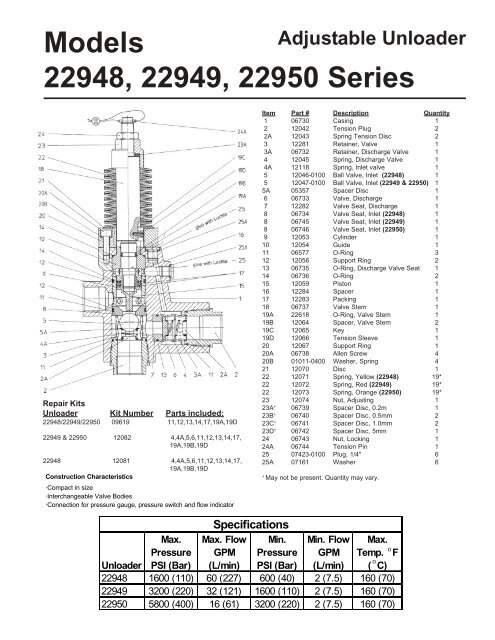
Adjustable Unloader<br />
<strong>22948</strong>, <strong>22949</strong>, <strong>22950</strong> <strong>Series</strong><br />
Repair Kits<br />
Unloader Kit Number Parts included:<br />
<strong>22948</strong>/<strong>22949</strong>/<strong>22950</strong> 09619 11,12,13,14,17,19A,19D<br />
<strong>22949</strong> & <strong>22950</strong> 12082 4,4A,5,6,11,12,13,14,17,<br />
19A,19B,19D<br />
<strong>22948</strong> 12081 4,4A,5,6,11,12,13,14,17,<br />
19A,19B,19D<br />
Construction Characteristics<br />
·Compact in size<br />
·Interchangeable Valve Bodies<br />
·Connection for pressure gauge, pressure switch and flow indicator<br />
Item Part # Description Quantity<br />
1 06730 Casing 1<br />
2 12042 Tension Plug 2<br />
2A 12043 Spring Tension Disc 2<br />
3 12281 Retainer, Valve 1<br />
3A 06732 Retainer, Discharge Valve 1<br />
4 12045 Spring, Discharge Valve 1<br />
4A 12118 Spring, Inlet valve 1<br />
5 12046-0100 Ball Valve, Inlet (<strong>22948</strong>) 1<br />
5 12047-0100 Ball Valve, Inlet (<strong>22949</strong> & <strong>22950</strong>) 1<br />
5A 05357 Spacer Disc 1<br />
6 06733 Valve, Discharge 1<br />
7 12282 Valve Seat, Discharge 1<br />
8 06734 Valve Seat, Inlet (<strong>22948</strong>) 1<br />
8 06745 Valve Seat, Inlet (<strong>22949</strong>) 1<br />
8 06746 Valve Seat, Inlet (<strong>22950</strong>) 1<br />
9 12053 Cylinder 1<br />
10 12054 Guide 1<br />
11 06577 O-Ring 3<br />
12 12056 Support Ring 2<br />
13 06735 O-Ring, Discharge Valve Seat 1<br />
14 06736 O-Ring 2<br />
15 12059 Piston 1<br />
16 12284 Spacer 1<br />
17 12283 Packing 1<br />
18 06737 Valve Stem 1<br />
19A 22618 O-Ring, Valve Stem 1<br />
19B 12064 Spacer, Valve Stem 2<br />
19C 12065 Key 1<br />
19D 12066 Tension Sleeve 1<br />
20 12067 Support Ring 1<br />
20A 06738 Allen Screw 4<br />
20B 01011-0400 Washer, Spring 4<br />
21 12070 Disc 1<br />
22 12071 Spring, Yellow (<strong>22948</strong>) 19*<br />
22 12072 Spring, Red (<strong>22949</strong>) 19*<br />
22 12073 Spring, Orange (<strong>22950</strong>) 19*<br />
23 12074 Nut, Adjusting 1<br />
23A + 06739 Spacer Disc, 0.2m 1<br />
23B + 06740 Spacer Disc, 0.5mm 2<br />
23C + 06741 Spacer Disc, 1.0mm 2<br />
23D + 06742 Spacer Disc, 5mm 1<br />
24 06743 Nut, Locking 1<br />
24A 06744 Tension Pin 1<br />
25 07423-0100 Plug, 1/4" 6<br />
25A 07161 Washer 6<br />
+<br />
May not be present. Quantity may vary.<br />
Specifications<br />
Unloader<br />
Max.<br />
Pressure<br />
PSI (Bar)<br />
Max. Flow<br />
GPM<br />
(L/min)<br />
Min.<br />
Pressure<br />
PSI (Bar)<br />
Min. Flow<br />
GPM<br />
(L/min)<br />
Max.<br />
o<br />
Temp. F<br />
o<br />
( C)<br />
<strong>22948</strong> 1600 (110) 60 (227) 600 (40) 2 (7.5) 160 (70)<br />
<strong>22949</strong> 3200 (220) 32 (121) 1600 (110) 2 (7.5) 160 (70)<br />
<strong>22950</strong> 5800 (400) 16 (61) 3200 (220) 2 (7.5) 160 (70)
Operation<br />
The whole discharge must be guided through the valve. Should the actual operating pressure exceed the adjusted operating pressure, the valve then acts<br />
as a pressure regulator. The valve switches to pressure-free bypass operation when the spray gun shuts off and the spray pressure between gun and valve<br />
remains idle.<br />
The valve can be operated together with several spray guns. It is also possible to connect several pumps to one common discharge line.<br />
Service and Adjustment<br />
Re-servicing and adjusting work is only to be carried out by skilled tradesmen.<br />
Safety Instructions<br />
Observe direction of flow. The bypass must under no circumstances be closed or fitted with any shut-off device.<br />
To Renew Piston Rod Seals and Sleeves<br />
Unscrew nuts (24+23). Remove spring pack (22). With a 6mm allen wrench, unscrew the 4 inner hexagon screws (20A) and remove spring support (20).<br />
Remove woodruff key (19C) and remove inlet tensioning plug (2). Remove spring (4A), ball (5) and spacer disc (5A). Push out piston rod (18) downwards<br />
together with inner parts (8, and 9). Remove piston body (15) with a size 19 wrench and pull piston rod out of guide case (10). Cut out worn seals and replace.<br />
Then carefully clip O-ring (19A) and support rings (19B) onto the piston rod. Note order of installation. Re-install guide sleeve (10) and spacer (16). Put<br />
the packing on the piston rod. Check casing (1) surfaces and inner parts for dirt or damage as this will cause the seals to wear out quickly. Check O-rings<br />
(11&14) and support rings (12) and replace as necessary. Remount piston body to piston rod with Loctite 648. Re-assemble in reverse order. Grease<br />
all parts lightly with Silicone before reinstalling.<br />
To Check and Replace Valves<br />
Remove the plugs (2) and check whether the balls (5) or valve plate (6) are worn out. Remove valve seats (8, 7) with clipring pliers and check surfaces<br />
for damage. Check O-rings (11) and replace as necessary.<br />
To Adjust Pressure<br />
1. Open valve so that it is completely tension-free, i. e. loosen nut (24) and adjusting nut (23) so that the piston rod can be moved by hand.<br />
2. Spring pack is tensioned by adjusting nut (23) while the pump is running and with open gun (if more than one gun is used, all have to be open) until<br />
required operating pressure is attained and no more water runs out on the bypass side. Then lock nut (24) to adjusting nut (23). If the nozzle hole corresponds<br />
exactly to the flow-rate and pressure of the pump, no more water will run out over the bypass after the required pressure has been attained.<br />
If the nozzle hole is too small and the whole output won’t go through the nozzle after the max. pump pressure has been reached, on no account is the<br />
valve to be adjusted higher than the max. operating pressure of the pump. In this case, the bypass should be partially left open. It is however, advisable<br />
to install suitable nozzles.<br />
Troubleshooting Guide<br />
Problem Cause Remedy<br />
Leaky gun<br />
Repair gun<br />
Leaky pressure pipe<br />
Seal pressure pipe<br />
Valve switches<br />
Leaky sleeve<br />
Replace O-rings.<br />
repeatedly when gun is<br />
Replace kick-back valve body or<br />
closed<br />
Worn out kick-back valve body o-ring or examine valve seat.<br />
Leaky seal (12,14)<br />
Renew seal<br />
Leaky piston rod<br />
Defective O-Ring / support ring<br />
Replace piston rod seals and<br />
examine surfaces in guide plug<br />
Leaky bypass at nominal<br />
pressure<br />
Nozzle too small, too much water Install larger nozzle<br />
Examine and renew as<br />
necessary, ball (5) and bypass<br />
Worn out bypass valve valve body (8)<br />
Pressure Gauge shows<br />
high pressure peaks<br />
when shutting off gun<br />
Valve set too high above<br />
operating pressure<br />
Dirty Valve<br />
Turn back adjusting nut (23) and<br />
hexagon nut (24)<br />
Clean valve (removing lime<br />
deposits, etc.<br />
Grease parts before reinstalling.<br />
<strong>Giant</strong> <strong>Industries</strong>, Inc. 900 N. Westwood Ave. P.O. Box 3187 Toledo, Ohio 43607<br />
PHONE (419) 531-4600 / FAX (419) 531-6836 www.giantpumps.com<br />
© Copyright 2012 <strong>Giant</strong> <strong>Industries</strong>, Inc.<br />
07/12 <strong>22948</strong>-50.PMD