Pump Specifications - Aqua Blast
Pump Specifications - Aqua Blast
Pump Specifications - Aqua Blast

You also want an ePaper? Increase the reach of your titles
YUMPU automatically turns print PDFs into web optimized ePapers that Google loves.
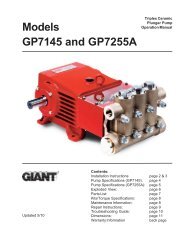
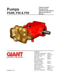
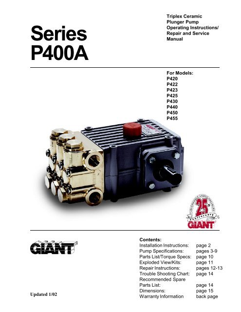
SeriesP400ATriplex CeramicPlunger <strong>Pump</strong>Operating Instructions/Repair and ServiceManualFor Models:P420P422P423P425P430P440P450P455Updated 1/02Contents:Installation Instructions: page 2<strong>Pump</strong> <strong>Specifications</strong>: pages 3-9Parts List/Torque Specs: page 10Exploded View/Kits: page 11Repair Instructions: pages 12-13Trouble Shooting Chart: page 14Recommended SpareParts List: page 14Dimensions: page 15Warranty Information back page
INSTALLATION INSTRUCTIONSInstallation of the Giant Industries, Inc.,pump is not a complicated procedure, butthere are some basic steps common to allpumps. The following information is to beconsidered as a general outline for installation.If you have unique requirements, pleasecontact Giant Industries, Inc. or your localdistributor for assistance.1. The pump should be installed flat on a base toa maximum of a 15 degree angle of inclinationto ensure optimum lubrication.2. The inlet to the pump should be sized for theflow rate of the pump with no unnecessaryrestrictions that can cause cavitation. Teflontape should be used to seal all joints. If pumpsare to be operated at temperatures in excess of160 0 F, it is important to insure a positive headto the pump to prevent cavitation.3. The discharge plumbing from the pumpshould be properly sized to the flow rate toprevent line pressure loss to the work area. It isessential to provide a safety bypass valvebetween the pump and the work area to protectthe pump from pressure spikes in the event of ablockage or the use of a shut-off gun.4. Use of a dampener is necessary to minimizepulsation at drive elements, plumbing, connections,and other system areas. The use of adampener with Giant Industries, Inc. pumps isoptional, although recommended by GiantIndustries, Inc. to further reduce system pulsation.Dampeners can also reduce the severity ofpressure spikes that occur in systems using ashut-off gun. A dampener must be positioneddownstream from the unloader.5. Crankshaft rotation on Giant Industries, Inc.pumps should be made in the direction designatedby the arrows on the pump crankcase.Reverse rotation may be safely achieved byfollowing a few guidelines available uponrequest from Giant Industries, Inc. Requiredhorsepower for system operation can be obtainedfrom the charts on pages 3-5 and 8-9.6. Before beginning operation of your pumpingsystem, remember: Check that the crankcaseand seal areas have been properly lubricated perrecommended schedules. Do not run the pumpdry for extended periods of time. Cavitation willresult in severe damage. Always remember tocheck that all plumbing valves are open and thatpumped media can flow freely to the inlet of thepump.Finally, remember that high pressure operation in a pump system has many advantages. But, if it is used carelesslyand without regard to its potential hazard, it can cause serious injury.IMPORTANT OPERATING CONDITIONSFailure to comply with any of these conditions invalidates the warranty.1. Prior to initial operation, add oil to thecrankcase so that oil level is between the twolines on the oil dipstick. DO NOT OVERFILL.Use Giant Synthetic OilCrankcase oil should be changed after thefirst 50 hours of operation, then at regularintervals of 500 hours or less depending onoperating conditions.2. <strong>Pump</strong> operation must not exceed ratedpressure, volume, or RPM. A pressure reliefdevice must be installed in the discharge of thesystem.3. Acids, alkalines, or abrasive fluids cannot bepumped unless approval in writing is obtainedbefore operation from Giant Industries, Inc.4. Run the pump dry approximately 10 secondsto drain the water before exposure to freezingtemperatures.NOTE: Contact Giant Industries for Service School Information. Phone: (419)-531-46002
* Intermittent duty onlyConsult the factory for special requirements that must be met if the pump isto operate beyond one or more of the limits specified above.NOTES:<strong>Specifications</strong>Model P422Volume ....................................................................................................... Up to 10 GPMDischarge Pressure ..................................................................................... Up to 2500 PSIInlet Pressure .............................................................................................. -4.35 to 145 PSIStroke ......................................................................................................... 24mmRPM ........................................................................................................... Up to 1450 RPMPlunger Diameter ........................................................................................ 22mmTemperature of <strong>Pump</strong>ed Fluids ................................................................... Up to 160 o FInlet Ports ................................................................................................... 1" NPTDischarge Ports........................................................................................... (2) 3/4" NPTShaft Rotation ................................................................................. Top of pulley towards manifoldCrankshaft Diameter ................................................................................... 28mmKey Width .................................................................................................. 8mmShaft Mounting ........................................................................................... Either side 1Weight ........................................................................................................ 36lbs. 11oz.Crankcase capacity ..................................................................................... 30fl.oz.Volumetric Efficiency @ 1450 .................................................................... 0.95Mechanical Efficiency @ 1450 ................................................................... 0.83In order to drive the pump from the side opposite the present shaftextension, simply remove the valve casing from the crankcase androtate the pumps 180 degrees to the desired position. Be certain torotate the seal case (item #20) as well, so that the weep holes aredown at the six o'clock position. Exchange the oil fill and the oildrain plugs, also. Refer to the repair instructions as necessary forthe proper assembly sequence.P422 HORSEPOWER REQUIREMENTSRPM GPM 1000 PSI 1500 PSI 2200 PSI 2500 PSI 3000 PSI900 6.2 4.3 6.4 9.3 10.7 12.81050 7.2 5.0 7.4 10.8 12.4 14.91160 8.0 5.5 8.3 12.1 13.8 16.61300 8.9 6.1 9.2 13.4 15.3 18.41450 10.0 6.9 10.3 15.1 17.2 20.7SPECIAL NOTE:The theoretical gallons per revolution(gal/rev) is 0.0069.To find specific outputs at various RPM,use the formula: GPM = 0.0069 x RPMHORSEPOWER RATINGS:The rating shown are the powerrequirements for the pump. Gasengine power outputs must beapproximately twice the pumppower requirements shown above.We recommend a 1.15 service factorbe specified when selecting anelectric motor as the power source.To compute specific pump horsepower requirements, use thefollowing formula:HP = (GPM X PSI) / 14504
<strong>Specifications</strong>Model P423Volume ....................................................................................................... Up to 8.3 GPMDischarge Pressure ..................................................................................... Up to 2600 PSIInlet Pressure .............................................................................................. -4.35 to 145 PSIStroke ......................................................................................................... 20mmRPM ........................................................................................................... Up to 1450 RPMPlunger Diameter ........................................................................................ 22mmTemperature of <strong>Pump</strong>ed Fluids ................................................................... Up to 160 o FInlet Ports ................................................................................................... (2) 1" NPTDischarge Ports........................................................................................... (2) 3/4" NPTShaft Rotation ................................................................................. Top of pulley towards manifoldCrankshaft Diameter ................................................................................... 28mmKey Width .................................................................................................. 8mmShaft Mounting ........................................................................................... Either side 1Weight ........................................................................................................ 36lbs. 11oz.Crankcase capacity ..................................................................................... 30fl.oz.Volumetric Efficiency @ 1450 .................................................................... 0.95Mechanical Efficiency @ 1450 ................................................................... 0.83* Intermittent duty onlyConsult the factory for special requirements that must be met if the pump isto operate beyond one or more of the limits specified above.NOTES:In order to drive the pump from the side opposite the present shaftextension, simply remove the valve casing from the crankcase androtate the pumps 180 degrees to the desired position. Be certain torotate the seal case (item #20) as well, so that the weep holes aredown at the six o'clock position. Exchange the oil fill and the oildrain plugs, also. Refer to the repair instructions as necessary forthe proper assembly sequence.P423 HORSEPOWER REQUIREMENTSRPM GPM 1000 PSI 1500 PSI 2000 PSI 2600 PSI900 5.1 3.5 5.3 7.0 9.11050 6.0 4.1 6.2 8.2 10.81160 6.6 4.6 6.8 9.0 11.81300 7.4 5.1 7.7 10.1 13.31450 8.3 5.7 8.6 11.4 14.9SPECIAL NOTE:The theoretical gallons per revolution(gal/rev) is 0.00572.To find specific outputs at various RPM,use the formula: GPM = 0.00572 x RPMHORSEPOWER RATINGS:The rating shown are the powerrequirements for the pump. Gasengine power outputs must beapproximately twice the pumppower requirements shown above.We recommend a 1.15 service factorbe specified when selecting anelectric motor as the power source.To compute specific pump horsepower requirements, use thefollowing formula:HP = (GPM X PSI) / 14505
<strong>Specifications</strong>Model P425Volume ....................................................................................................... Up to 10.7 GPMDischarge Pressure ..................................................................................... Up to 2100 PSIInlet Pressure .............................................................................................. -4.35 to 145 PSIStroke ......................................................................................................... 20mmRPM ........................................................................................................... Up to 1450 RPMPlunger Diameter ........................................................................................ 25mmTemperature of <strong>Pump</strong>ed Fluids ................................................................... Up to 160 o FInlet Ports ................................................................................................... (2) 1" NPTDischarge Ports........................................................................................... (2) 3/4" NPTShaft Rotation ................................................................................. Top of pulley towards manifoldCrankshaft Diameter ................................................................................... 28mmKey Width .................................................................................................. 8mmShaft Mounting ........................................................................................... Either side 1Weight ........................................................................................................ 36lbs. 11oz.Crankcase capacity ..................................................................................... 30fl.oz.Volumetric Efficiency @ 1450 .................................................................... 0.95Mechanical Efficiency @ 1450 ................................................................... 0.83* Intermittent duty onlyConsult the factory for special requirements that must be met if the pump isto operate beyond one or more of the limits specified above.NOTES:In order to drive the pump from the side opposite the present shaftextension, simply remove the valve casing from the crankcase androtate the pumps 180 degrees to the desired position. Be certain torotate the seal case (item #20) as well, so that the weep holes aredown at the six o'clock position. Exchange the oil fill and the oildrain plugs, also. Refer to the repair instructions as necessary forthe proper assembly sequence.P425 HORSEPOWER REQUIREMENTSRPM GPM 1000 PSI 1500 PSI 1700 PSI 2100 PSI750 5.5 3.8 5.7 6.4 8.0900 6.6 4.6 6.8 7.7 9.61010 7.5 5.2 7.8 8.7 10.91120 8.3 5.7 8.6 9.7 12.01240 9.1 6.3 9.4 10.6 13.21450 10.7 7.4 11.1 12.5 15.5SPECIAL NOTE:The theoretical gallons per revolution(gal/rev) is 0.00740.To find specific outputs at various RPM,use the formula: GPM = 0.00740 x RPMHORSEPOWER RATINGS:The rating shown are the powerrequirements for the pump. Gasengine power outputs must beapproximately twice the pumppower requirements shown above.We recommend a 1.15 service factorbe specified when selecting anelectric motor as the power source.To compute specific pump horsepower requirements, use thefollowing formula:HP = (GPM X PSI) / 14506
<strong>Specifications</strong>Model P430AVolume ................................................................................................... Up to 7.5 GPMDischarge Pressure ................................................................................. Up to 3200 PSIInlet Pressure .......................................................................................... -4.35 to 145 PSIStroke..................................................................................................... 24mmRPM....................................................................................................... Up to 1450 RPMPlunger Diameter.................................................................................... 18mmTemperature of <strong>Pump</strong>ed Fluids ............................................................... Up to 160 o FInlet Ports ............................................................................................... (2) 3/4" BSPDischarge Ports ...................................................................................... (2) 3/4" BSPShaft Rotation............................................................................. Top of pulley towards manifoldCrankshaft Diameter ............................................................................... 28mmKey Width .............................................................................................. 8mmShaft Mounting....................................................................................... Either side 1Weight .................................................................................................... 36lbs. 11oz.Crankcase capacity ................................................................................. 30fl.oz.Volumetric Efficiency @ 1450 ................................................................ 0.95Mechanical Efficiency @ 1450 ............................................................... 0.82Consult the factory for special requirements that must be met if the pump isto operate beyond one or more of the limits specified above.NOTES:In order to drive the pump from the side opposite the present shaftextension, simply remove the valve casing from the crankcase androtate the pumps 180 degrees to the desired position. Be certain torotate the seal case (item #20) as well, so that the weep holes aredown at the six o'clock position. Exchange the oil fill and the oildrain plugs, also. Refer to the repair instructions as necessary forthe proper assembly sequence.P430 HORSEPOWERREQUIREMENTSRPM GPM 1000 2000 3000 3200PSI PSI PSI PSI920 4.8 3.3 6.6 9.9 10.61050 5.4 3.7 7.4 11.2 11.91185 6.1 4.2 8.4 12.6 13.51315 6.8 4.7 9.4 14.1 15.01450 7.5 5.2 10.3 15.5 16.6SPECIAL NOTE:The theoretical gallons per revolution(gal/rev) is 0.00514.To find specific outputs at various RPM,use the formula: GPM = 0.00514 x RPMHORSEPOWER RATINGS:The rating shown are the powerrequirements for the pump. Gasengine power outputs must beapproximately twice the pumppower requirements shown above.We recommend a 1.15 service factorbe specified when selecting anelectric motor as the power source.To compute specific pump horsepower requirements, use thefollowing formula:HP = (GPM X PSI) / 14507
<strong>Specifications</strong>Model P440AVolume ....................................................................................................... Up to 5.5 GPMDischarge Pressure ..................................................................................... Up to 4000 PSIInlet Pressure .............................................................................................. -4.35 to 145 PSIStroke ......................................................................................................... 20mmRPM ........................................................................................................... Up to 1450 RPMPlunger Diameter ........................................................................................ 18mmTemperature of <strong>Pump</strong>ed Fluids ................................................................... Up to 160 o FInlet Ports ................................................................................................... (2) 3/4" BSPDischarge Ports........................................................................................... (2) 3/4" BSPShaft Rotation ................................................................................. Top of pulley towards manifoldCrankshaft Diameter ................................................................................... 28mmKey Width .................................................................................................. 8mmShaft Mounting ........................................................................................... Either side 1Weight ........................................................................................................ 36lbs. 11oz.Crankcase capacity ..................................................................................... 30fl.oz.Volumetric Efficiency @ 1450 .................................................................... 0.95Mechanical Efficiency @ 1450 ................................................................... 0.82Consult the factory for special requirements that must be met if the pump isto operate beyond one or more of the limits specified above.NOTES:In order to drive the pump from the side opposite the present shaftextension, simply remove the valve casing from the crankcase androtate the pumps 180 degrees to the desired position. Be certain torotate the seal case (item #20) as well, so that the weep holes aredown at the six o'clock position. Exchange the oil fill and the oildrain plugs, also. Refer to the repair instructions as necessary forthe proper assembly sequence.P440 HORSEPOWERREQUIREMENTSRPM GPM 1000 2000 3000 4000PSI PSI PSI PSI920 3.5 2.4 4.9 7.3 9.71050 4.0 2.8 5.5 8.3 11.11185 4.5 3.1 6.3 9.4 12.51315 5.0 3.5 6.9 10.4 13.91450 5.5 3.8 7.7 11.5 15.3SPECIAL NOTE:The theoretical gallons per revolution(gal/rev) is 0.00379.To find specific outputs at various RPM,use the formula: GPM = 0.00379 x RPMHORSEPOWER RATINGS:The rating shown are the powerrequirements for the pump. Gasengine power outputs must beapproximately twice the pumppower requirements shown above.We recommend a 1.15 service factorbe specified when selecting anelectric motor as the power source.To compute specific pump horsepower requirements, use thefollowing formula:HP = (GPM X PSI) / 14508
<strong>Specifications</strong>Model P450A/P455Volume ....................................................................................................... Up to 5.5 GPMDischarge Pressure ..................................................................................... Up to 5000 PSIInlet Pressure .............................................................................................. Up to 90 PSIStroke ......................................................................................................... 20mmRPM ........................................................................................................... Up to 1450 RPMPlunger Diameter ........................................................................................ 18mmTemperature of <strong>Pump</strong>ed Fluids ................................................................... Up to 160 o FInlet Ports ................................................................................................... (2) 1/2" BSPDischarge Ports........................................................................................... (2) 1/2" BSPShaft Rotation ................................................................................. Top of pulley towards manifoldCrankshaft Diameter ................................................................................... 28mmKey Width .................................................................................................. 8mmShaft Mounting ........................................................................................... Either side 1Weight ........................................................................................................ 36lbs. 11oz.Crankcase capacity ..................................................................................... 30fl.oz.Volumetric Efficiency @ 1450 .................................................................... 0.92Mechanical Efficiency @ 1450 ................................................................... 0.86Consult the factory for special requirements that must be met if the pump isto operate beyond one or more of the limits specified above.NOTES:In order to drive the pump from the side opposite the present shaftextension, simply remove the valve casing from the crankcase androtate the pumps 180 degrees to the desired position. Be certain torotate the seal case (item #20) as well, so that the weep holes aredown at the six o'clock position. Exchange the oil fill and the oildrain plugs, also. Refer to the repair instructions as necessary forthe proper assembly sequence.P450/P455 HORSEPOWERREQUIREMENTSRPM GPM 2000 3000 4000 5000PSI PSI PSI PSI800 3.0 4.2 6.3 8.4 10.5933 3.5 4.9 7.3 9.8 12.21066 4.0 5.6 8.4 11.1 13.91200 4.5 6.3 9.4 12.5 15.71450 5.5 7.6 11.4 15.2 18.9SPECIAL NOTE:The theoretical gallons per revolution(gal/rev) is 0.00379.To find specific outputs at various RPM,use the formula: GPM = 0.00379 x RPMHORSEPOWER RATINGS:The rating shown are the powerrequirements for the pump. Gasengine power outputs must beapproximately twice the pumppower requirements shown above.We recommend a 1.15 service factorbe specified when selecting anelectric motor as the power source.To compute specific pump horsepower requirements, use thefollowing formula:HP = (GPM X PSI) / 14509
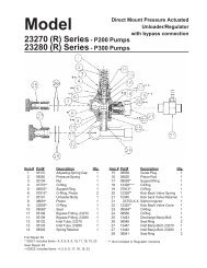
P400A SERIES PARTS LISTA=P420 B= P422 C=P430 D=P440 E=P450 F=P455 G=P423 H=P425ITEM PART DESCRIPTION QTY.1 08377 Crankcase 12 08378 Oil Fill Plug with Gasket 13 06479 Crankcase cover 13A 07186 Oil Sight Glass w/ Gasket 14 08380 O-Ring 15 07606 Oil Drain Plug 15A 07182 Gasket for Oil Drain Plug 15B 08092 Plug with Gasket 16 01010 Screw 46A 01011 Spring Washer 47 08471 Bearing Cover Open 18 08472 Bearing Cover Closed 18A 06245 Shim 18B 06330 Shim (May not be present) 19 01016 O-Ring 210 07114 Screw with Washer 811 07459 Radial Shaft Seal 112 08473 Bearing 112A 08474 Bearing 113 08475 Crankshaft (A,B,C) 113 08482 Crankshaft (D,E,F,G,H) 114 08091 Fitting Key 115 08390 Connecting Rod Assembly 315A 07311 Screw with Washer 616 06622 Plunger Assy., 18mm (C,F) 316 08391 Plunger Assy., 25mm, (A, H)For items 16A-16G 316 06246 Plunger Assy., 22mm, (B,G)For items 16A-16G 316 06622 Plunger Assy., 18mm, (F)For items 16A-16G 316 08383 Plunger Assy.,18mm (C,D,E)For items 16A-16G 316A 08384 Plunger Base 316B 08398 Plunger Pipe, 25mm (A, H) 316B 06247 Plunger Pipe, 22mm (B,G) 316B 08397 Plunger Pipe, 18mm (C,D,E,F) 316C 07256 Centering Sleeve 316D 08399 Tensioning Screwing 316E 07023 O-Ring 316F 07203 Backup Ring 316G 07258 Copper Washer (A,B,C,D,E,G,H) 316G 07676 Copper Washer (F) 316H 06431 Oil Scraper 317 06790 Crosshead Pin 319 08366 Oil Seal 320 06771 Seal Case (A, H) 320 06770 Seal Case (B,G) 3ITEM PART DESCRIPTION QTY.20 06443 Seal Case (C,D,E,F) 320A 06772 Gear Seal Adapter 321 07266 O-Ring 322 08059 O-Ring 323 12254 V-Sleeve, 25mm (A,H)23 06249 V-Sleeve with Support Ring, 322mm (B,G)23 08477 V-Sleeve, 18mm (C,D,E,F) 623A 06251 Spacer Ring (B,G) 323B 12255 Weep Seal (A,H) 323B 13390 Weep Seal with Support Ring (B,G) 324 08376 Pressure Ring (A,H) 624 06252 Pressure Ring (B,G) 324 07929 Pressure Ring (C,D,E,F) 325 08394 Weep Return Ring (A,H) 325 06254 Weep Return Ring (B,G) 325 08402 Weep Return Ring (C,D,E,F) 326 08395 Manifold (A,H) - Brass 126 06255 Manifold (B,G) - Brass 126 08409 Manifold (C) - Brass 126 08403 Manifold (D) - Bronze 126 08470 Aluminum Bronze (E) 126 06623 Manifold (F) 127A 08408 Valve Assy. (A,B,G,H) 627A 06810 Valve Assy. (C,D,E,F) 627 08370 Valve Seat (A,B,G,H) 627 08404 Valve Seat (C,D,E,F) 628 06791 Valve Plate (A,B,G,H) 628 06809 Valve Plate (C,D,E,F) 629 06377 Valve Spring (A,B,G,H) 629 07906 Valve Spring (C,D,E,F) 630 08372 Valve Spring Retainer (A,B,G,H) 630 07907 Valve Spring Retainer (C,D,E,F) 631 07212 O-Ring (A,B,G,H) 631 07770 O-Ring (C,D,E,F) 632 08373 Plug (A,B,G,H) 632 06624 Plug (F) 632 08406 Plug (C,D,E) 633 07214 O-Ring (A,B,G,H) 633 06487 O-Ring (F) 633 07489 O-Ring (C,D,E) 634 08396 Cap Screw (A,B,C,D,E,G,H) 834 08484 Cap Screw (F) 836 12250 Plug, 1/2" BSP (E,F Only) 236A 06272 O-Ring (E,F Only) 237 07703 Plug, G 3/4" (C,D Only) 137A 07704 Copper Gasket (C,D Only) 1P400A SERIES TORQUE SPECIFICATIONSPosition Item# Description Torque Amount15A 07311 Screw with Washer 216 in.-lbs.16D 08399 Tensioning Screw 240 in.-lbs.32 08373 Plug (P420, P422, P423, P425) 125 ft.-lbs.32 06624 Plug (P455) 125 ft.-lbs.32 08406 Plug (P430, P440, P450) 110 ft.-lbs.34 08396/08484 Cap Screw 35 ft.-lbs.10
Exploded View - P400A Series**+P400A SERIES REPAIR KITS** This is item 37 for P430, P440 only+ This is item 37A for P430, P440 onlyPlunger Packing KitsP420, P425 # 09140Item Part # Description Qty21 07266 O-Ring 322 08059 O-Ring 323 12254 V-Sleeve 323B 12255 Weep Seal 324 08376 Pressure Ring 6P422, P423 # 09295Item Part # Description Qty21 07266 O-Ring 322 08059 O-Ring 323 06249 V-Sleeve with Support Ring 323B 13390 Weep Seal 324 06252 Pressure Ring 3P430, P440, P450, P455 # 09141Item Part # Description Qty21 07266 O-Ring 322 08059 O-Ring 323 08477 V-Sleeve 624 07929 Pressure Ring 311Valve Assembly KitsP420, P422, P423, P425 # 09143Item Part # Description Qty.27A 08408 Valve Assembly, Complete 633 07214 O-Ring 6P430, P440, P450, P455 # 09142Item Part # Description Qty27A 06810 Valve Assembly, Complete 633 06487 O-Ring (P455 only) 633 07489 O-Ring (except P455) 6Oil Seal KitP400 Series # 09306Item Part # Description Qty19 08366 Oil Seal 3Optional Viton Seal KitP430, P440, P450, P455 # 09456Item Part # Description Qty23 07902-0010 V-Sleeve 6w/support ring, Viton24 07904 Pressure Ring 6
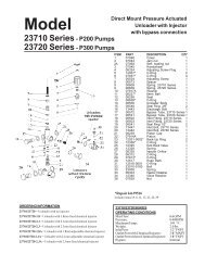
REPAIR INSTRUCTIONS - P400A SERIESNote: Always take time to lubricate all metal and nonmetal parts with a light film of oil before reassembly. This step will ensure properfit, at the same time protecting the pump nonmetal parts (i.e., the elastomers) from cutting and scoring.1) With a socket wrench,remove the three dischargevalve plugs and three inletvalve plugs (32). Inspectthe o-ring (33) for wear andreplace if damaged.2) Using needle nose pliers,remove the inlet and dischargevalve assemblies(27A). Note: It may becomeneccesary to remove thevalve seat (27) from thevalve casing using aslidehammer.3) By inserting a small screwdriver between the valve seat(27) and the valve spring retainer(30), the valve assemblycan be separated.4) Remove the o-ring (31).Inspect all parts for wear andreplace as necessary. Applyone drop of loctite 243 to thevalve plugs (32) and tightento 125 ft. lbs.7) Remove the pressure rings(24) and v-sleeves (23 -Note: P422 & P423 pumpshave a support ring) fromthe valve casing (26).5) Use a 8mm allen wrench toremove the 8 socket headcap screws (34). Carefullyslide the valve casing (26)out over the plungers.8) Remove the weep groovedseal (23 or 23B) togetherwith pressure ring (24 _P420 and P425 only) outof the seal adaptor (20).Check O-rings (21).126) Remove seal adaptors (20)and weep return rings (25)from the valve casing.IMPORTANT! The groovedseal (23) or respectivelygrooved seal pack (23A) onthe high-pressure side is to befitted carefully into the valvecasing (26) using a screwdriver.Under no circumstancesmust the seal surfacein the valve casing or the seallip be damaged.
REASSEMBLY INSTRUCTIONS - P400A SERIESIMPORTANT! Care must betaken that glue does not getbetween the plunger pipe (16B)and centring sleeve (16C). Theplunger pipe should not bestrained by eccentric tighteningof the tension screw or throughdamage to front surface ofplunger, otherwise it is liable tofracture.9) Check surfaces of plunger(16). Damaged surfacescause accelerated seal wear.Deposits of all kinds must beremoved from the plungers.IMPORTANT! Plungersurfaces are not to bedamaged. If there are limedeposits in the pump, caremust be taken that the dripreturnbore in parts (25)and (26) ensure trouble-freedrip-return.10) If the plunger pipe (16B), oroil seal (19) is worn, removetension screw (16D) and removealong with plungerpipe (16B). Check and cleanplunger surface (16A), checkoil scraper (16H). Removethe gear seal adapter (20A)and, if necessary, replace oilseals with seal lips facingcrankcase (1).Cover threadof tension screw (16D) witha thin film of Loctite andtighten carefully to 26 ft.-lbs.(35NM).11) After installation of highpressure seals (23 - Note:P422 and P423, also have asupport ring), place sealadaptor (20) with weep seals& pressure ring installed,weep return ring (25) and highpressure weep return ring (24)over plungers. Slide valvecasing over plungers and seatfirmly. Replace the 8 sockethead cap screws (34) andtighten to 35 ft.-lbs. in acrossing pattern(as shown below).684 21 375Contact Giant Industries for service school information. Phone: (419) 531-460013
PUMP SYSTEM MALFUNCTIONMALFUNCTION CAUSE REMEDYThe Pressure and/ Worn packing seals Replace packing sealsor the Delivery Broken valve spring Replace springDrops Belt slippageWorn or Damaged nozzleTighten or Replace beltReplace nozzleFouled discharge valveClean valve assemblyFouled inlet strainerWorn or Damaged hoseClean strainerRepair/Replace hoseWorn or Plugged relief valve on pump Clean, Reset, and Replace worn partsCavitationpump for restrictionsCheck suction lines on inlet ofUnloaderCheck for proper operationWater in crankcase High humidity Reduce oil change intervalWorn sealsReplace sealsNoisy Operation Worn bearings Replace bearings, Refill crankcaseoil with recommended lubricantCavitationCheck inlet lines for restrictionsand/or proper sizingRough/PulsatingOperation withWorn packingInlet restrictionReplace packingCheck system for stoppage, airPressure Dropleaks, correctly sized inletplumbing to pumpAccumulator pressureRecharge/Replace accumulatorUnloaderCheck for proper operationCavitationCheck inlet lines for restrictionsand/or proper size<strong>Pump</strong> Pressure asgunRestricted discharge plumbing Re-size discharge plumbing to Drop atflow rate of pumpRated, PressureExcessive Worn plungers Replace plungersLeakage Worn packing/seals Adjust or Replace packing sealsExcessive vacuumCracked plungersReduce suction vacuumReplace plungersInlet pressure too highReduce inlet pressureHigh Crankcase Wrong Grade of oil Giant oil is recommendedTemperature Improper amount of oil in crankcase Adjust oil level to proper amountPreventative Maintenance Check-List & Recommended Spare Parts ListCheck Daily Weekly 50hrs Every Every Every500 hrs 1500 hrs 3000 hrsOil Level/QualityOil LeaksWater LeaksBelts, PulleyPlumbingXXXXXRecommended Spare PartsOil Change (1 Gallon) p/n 1154 X XSeal Spare Parts (1 kit/pump) X(See page 11 for kit list)Oil Seal Kit (1 kit/pump) X(See page 11 for kit lit)Valve Spare Parts (1 kit/pump) X(See page 11 for kit list)14
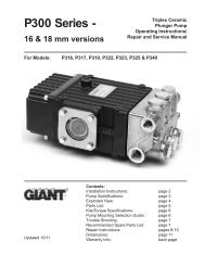
P400A SERIES DIMENSIONS (INCHES)15
GIANT INDUSTRIES LIMITED WARRANTYGiant Industries, Inc. pumps and accessories are warranted by the manufacturer to be free fromdefects in workmanship and material as follows:1. For portable pressure washers and self-service car wash applications, the dischargemanifolds will never fail, period. If they ever fail, we will replace them free of charge.Our other pump parts, used in portable pressure washers and in car wash applications,are warranted for five years from the date of shipment for all pumps used in NON-SALINE, clean water applications.2. One (1) year from the date of shipment for all other Giant industrial and consumerpumps.3. Six (6) months from the date of shipment for all rebuilt pumps.4. Ninety (90) days from the date of shipment for all Giant accessories.This warranty is limited to repair or replacement of pumps and accessories of which the manufacturer’sevaluation shows were defective at the time of shipment by the manufacturer. The following itemsare NOT covered or will void the warranty:1. Defects caused by negligence or fault of the buyer or third party.2. Normal wear and tear to standard wear parts.3. Use of repair parts other than those manufactured or authorized by Giant.4. Improper use of the product as a component part.5. Changes or modifications made by the customer or third party.6. The operation of pumps and or accessories exceeding the specifications set forthin the Operations Manuals provided by Giant Industries, Inc.Liability under this warranty is on all non-wear parts and limited to the replacement or repair of thoseproducts returned freight prepaid to Giant Industries which are deemed to be defective due toworkmanship or failure of material. A Returned Goods Authorization (R.G.A.) number and completedwarranty evaluation form is required prior to the return to Giant Industries of all products underwarranty consideration. Call (419)-531-4600 or fax (419)-531-6836 to obtain an R.G.A. number.Repair or replacement of defective products as provided is the sole and exclusive remedy providedhereunder and the MANUFACTURER SHALL NOT BE LIABLE FOR FURTHER LOSS, DAMAGES,OR EXPENSES, INCLUDING INCIDENTAL AND CONSEQUENTIAL DAMAGES DIRECTLY ORINDIRECTLY ARISING FROM THE SALE OR USE OF THIS PRODUCT.THE LIMITED WARRANTY SET FORTH HEREIN IS IN LIEU OF ALL OTHER WARRANTIES ORREPRESENTATION, EXPRESS OR IMPLIED, INCLUDING WITHOUT LIMITATION ANY WAR-RANTIES OR MERCHANTABILITY OR FITNESS FOR A PARTICULAR PURPOSE AND ALL SUCHWARRANTIES ARE HEREBY DISCLAIMED AND EXCLUDED BY THE MANUFACTURER.GIANT INDUSTRIES, INC., 900 N. Westwood Ave., P.O. Box 3187, Toledo, Ohio 43607PHONE (419) 531-4600, FAX (419) 531-6836, www.giantpumps.com© Copyright 2001 Giant Industries, Inc. 12/01 P400.PM6