PHQ250 Stoper - Parts HeadQuarters Inc
PHQ250 Stoper - Parts HeadQuarters Inc
PHQ250 Stoper - Parts HeadQuarters Inc

You also want an ePaper? Increase the reach of your titles
YUMPU automatically turns print PDFs into web optimized ePapers that Google loves.
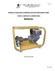
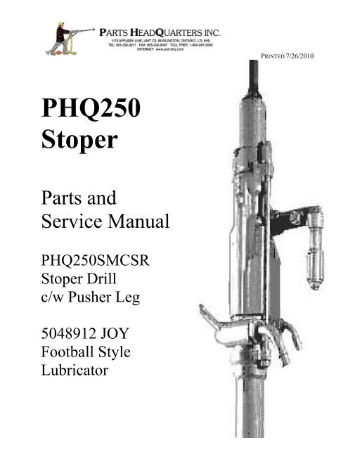
PRINTED 7/26/2010<br />
<strong>PHQ250</strong><br />
<strong>Stoper</strong><br />
<strong>Parts</strong> and<br />
Service Manual<br />
<strong>PHQ250</strong>SMCSR<br />
<strong>Stoper</strong> Drill<br />
c/w Pusher Leg<br />
5048912 JOY<br />
Football Style<br />
Lubricator
Page 2<br />
Safety Identification and Safeguards<br />
WARNING Read and understand all safety instructions carefully before operating this machine.<br />
Failing to follow these instructions may result in serious personal injury.<br />
Important Safeguards<br />
• Keep clear of rotating equipment and never wear loose clothing to tangle in machinery<br />
• Always maintain a clean and tidy work area. Pick up unnecessary items. Store tools.<br />
• Avoid dangerous working environments and lack of ventilation.<br />
• Do not operate equipment while under the influence of drugs, alcohol, or medication.<br />
• Keep visitors at a safe distance and away from the work area where they may be injured.<br />
• Wear protective equipment, hard hat, safety glasses, hearing protection and hard toed work boots.<br />
• Read and understand the operations manual and any and all labels affixed to the machine.<br />
• Use only genuine PHQ replacement parts. Failure to do so could cause rapid and severe damage to the<br />
machine or ultimately the operator. Pirate replacement parts may void the warranty of mating parts.<br />
• Employ qualified service technicians to repair rock drills. An un-trained mechanic could possibly make<br />
errors in installing parts and cause severe damage to mating parts in the machine.<br />
• Ensure that the drill and accessories comply with applicable company safety and health regulations.<br />
• Do not exceed the rated capacity of any piece of equipment.<br />
• Do not change or alter the drill, its components or accessories without prior approval from PHQ.<br />
• Unauthorized alteration voids the warranty, and could render the equipment unsafe.<br />
• Before moving a control, be certain what function it operates and the ramifications of that function.<br />
• Proper breathing protection must be worn when working with materials producing airborne particles.<br />
• Prolonged exposure to vibration causes serious arm/hand vibration syndrome disease (White Finger)<br />
• For additional information on training or start up, contact your PHQ representative.<br />
WARNING<br />
Operating a Rockdrill without lubricant or with incorrect lubricant is the leading cause of failure of rock<br />
drill parts. Lack of lubrication can rapidly cause EXTENSIVE DAMAGE to the working parts of this<br />
machine. All Rockdrill repairs should be preformed by properly trained and equipped personnel.<br />
NOTE: No claim for product warranty of premature failed parts will be considered when it is evident<br />
that the failures were caused by a prolonged lack of proper lubrication. No claim for product warranty<br />
of premature failed components will be considered by PHQ if parts other than those manufactured by<br />
PHQ are deemed to have caused the failure.
Certificate of Performance<br />
Page 3<br />
This certificate supplied with each drill and is signed by the assembly mechanic assuring that ‘the product<br />
has been tested and meets PHQ’s quality standards. It lists the actual test results achieved by running the<br />
drill on a PHQ test bench at the time of assembly.
Page 4<br />
Introduction and General Information<br />
Safety Identification and Safeguards….. 2<br />
Certificate of Performance..………….. 3<br />
Index………………………….……….. 4<br />
Standard Warranty…………………… 5<br />
Ordering <strong>Parts</strong>………………………… 6<br />
Returning <strong>Parts</strong>……………………….. 6<br />
Maintenance Procedures<br />
Rockdrill Repair Shop ………………. 7<br />
PHQ S250 Repair Tools……………… 8<br />
PHQ S250 <strong>Stoper</strong> Drill<br />
<strong>PHQ250</strong>SMCS <strong>Stoper</strong> Schematic……….. 9<br />
<strong>PHQ250</strong>SMCS <strong>Stoper</strong> <strong>Parts</strong> List………….. 10<br />
Maintenance Procedures………………….. 13<br />
Disassembly Procedures………………… 13<br />
<strong>Stoper</strong> Control Handle Removal………….. 13<br />
Air Connection Assembly Removal….…… 14<br />
Water Connection Assembly Removal……. 14<br />
Throttle Valve Assembly Removal…. 15<br />
Steel Retainer Removal..………………. 16<br />
Water Control Valve (Automatic) ……… 17<br />
Backhead Removal………………………. 18<br />
Front Head Removal………………….……. 18<br />
Ratchet Ring and Rifle Bar Removal……… 19<br />
Valve Chest Disassembly…………………. 19<br />
Inspection of Cylinder and Piston…… 21<br />
Front Cylinder Assembly Inspection... 21<br />
Chuck Insert Removal……………… 23<br />
Rifle Nut Removal………………….. 23<br />
Chuck Nut Removal………………… 24<br />
Servicing the <strong>Stoper</strong> Leg……………… 25<br />
Assembly Procedures …………………… 27<br />
Piston Valve and Ratchet Ring………. 27<br />
Rifle Bar Fronthead and Backhead……. 28<br />
Leg Side Rods and Holding Handle…..… 28<br />
Running in the drill…….………………… 29<br />
Testing the <strong>Stoper</strong>.…………….……….. 30<br />
Water testing procedure…..…….……….. 31<br />
Joy Football Style Lubricator<br />
Lubricator <strong>Parts</strong> Schematic………………… 34<br />
<strong>Parts</strong> Performance<br />
<strong>Stoper</strong> <strong>Parts</strong> Performance…………………. 33<br />
Troubleshooting Guides<br />
Rock drill will not start………..…...….. 35<br />
Rock drill runs erratically…..…………. 35<br />
Water problems………………..…...….. 35<br />
Sluggish running………..…..…………. 36<br />
Drill sounds good but runs poorly...….. 36<br />
Bronze cuttings coming out of the drill.. 37<br />
Drill parts wearing prematurely.…...….. 37<br />
Faulty Lubrication…………..…………. 37<br />
Pusher Leg not working properly...….. 38<br />
Drill Steel failing at the collar…..………. 38<br />
Drill steel does not rotate or weak rotation.. 39<br />
Stuck drill steel..…………..……………… 39<br />
Drill overheating...……………………….. 39
Page 5<br />
NOTE: PHQ continuously updates product literature to provide customers with the most current technical<br />
information available. Portions of this literature in time could contain information that may not be exactly<br />
representative of the current configuration of PHQ products. Contact your nearest PHQ representative for<br />
information on the latest product improvements and replacement literature available. The purpose of the<br />
manual is to provide service technicians with detailed information to achieve the maximum operating<br />
performance from PHQ products. <strong>Parts</strong> lists with corresponding exploded view schematic drawings are<br />
provided to aid in identifying parts needed for repairs and to facilitate ordering of proper parts for the<br />
assembly. Drawings are included at the appropriate area within the text. The drawings included are small<br />
through necessity. Large wall posters are available. PHQ personnel are proud to say they are backed up<br />
by over 50 years of experience in design, manufacture and operation of Percussive Drilling Equipment.<br />
Many of the accepted practices in use today were pioneered by some of the personnel working at PHQ.<br />
To obtain the best performance and life of the equipment regular maintenance is required.<br />
To obtain the best performance the machines should be operated in accordance with the instructions.<br />
Ensure proper safety apparel is worn when transporting, servicing or using the equipment.<br />
Ensure quality lubricant is used and the delivery system provides amounts sufficient to run the drill.<br />
Inspect and replace worn front end and chuck parts promptly to improve the life of drill rods.<br />
Ensure the drill is being operated correctly to avoid steel and drill rod misalignment.<br />
Check air supply pipes and hoses and connections for flow restrictions or ingress of contaminants.<br />
Listen to the drill for erratic running and insure the side rod bolts on the drill are properly torqued...<br />
Provide new employees with time to read this manual before allowing them to operate the equipment.<br />
Keep a master copy of this manual at hand at all times for reference should any questions arise.<br />
Standard Warranty<br />
For each new or used PHQ manufactured product and accessory, PHQ warrants that the product is free<br />
from defects in material and workmanship under normal; use and service for a 180 days from the date of<br />
first use (not to exceed one year from the date of shipment from a PHQ factory). The obligation under this<br />
warranty shall be limited to the replacement or repair of the failed product returned to PHQ. All warranty<br />
replacement is subject to inspection by a PHQ representative and the Quality Control Department at PHQ<br />
in Burlington, Ontario. PHQ will replace only parts that are judged to have been defective at the time of<br />
manufacture and assembly. This warranty does not apply to a product which has been altered, changed, or<br />
has been used and repaired then returned to a drill where the repaired part failed while in operation...<br />
PHQ states that the product described in this manual shall not be merchantable or fit for any other purpose<br />
other than the operations described in the manual. No other warranties are expressed or implied.<br />
Exclusive of Liability for Consequential Damages<br />
In no event shall PHQ be liable for a customer’s cost of lost production, increased cost, loss of profit,<br />
special indirect, incidental or consequential damages, and freight, brokerage, and shipping and storage<br />
charges.
Page 6<br />
Ordering <strong>Parts</strong><br />
PHQ requires the following procedures be followed and the proper information be supplied to expedite<br />
the filling of customer orders for parts and to eliminate delays and errors in shipping incorrect parts.<br />
1. List the model of the assembly (EG: <strong>PHQ250</strong>SMCS Muffled <strong>Stoper</strong> Drill).<br />
2. State the exact quantity of each item of parts required.<br />
3. Identify items with the description and part number as shown in the parts section of this manual.<br />
4. Specify the preferred method of shipment. (EG: Parcel Post. Courier, Truck Freight).<br />
5. For overseas shipments specify the preferred method of shipment. (EG Air freight or sea freight).<br />
Pricing is specified by PHQ in formal quotations and shipping terms can be included in quotations. All<br />
normal repeat part orders are priced according to INCOTerms2000 Ex-Works and FOB our factory in<br />
Burlington Ontario. Separate charges for transportation and export packing may apply.<br />
Returning of New or Damaged <strong>Parts</strong><br />
If a customer wishes to return parts to PH due to overstocking or whether for repairs, replacement, or<br />
warranty, a letter of explanation should first be sent by e-mail, mailed or faxed to:<br />
<strong>Parts</strong> <strong>HeadQuarters</strong> <strong>Inc</strong>.<br />
C2-1175 Appleby Line<br />
Burlington, Ontario<br />
Canada L7L 5H9<br />
ATTN: Sales Department<br />
sales@partshq.com<br />
Phn: 905-332-3271<br />
Fax: 905-332-9497<br />
This letter should specify the model number of the PHQ product (EG: <strong>PHQ250</strong>SMCS <strong>Stoper</strong> Drill) and<br />
list the parts by item that the customer wishes to return. The list should contain the Item part number,<br />
description and the quantity of each item. The letter should state the date of purchase (or order number) as<br />
well as a valid reason for requesting return. <strong>Parts</strong> returned by customers due to overstocking at the<br />
customers’ location will be subject to a percentage restocking charge by PHQ.<br />
DO NOT ship parts until authorized by PHQ Sales Department and shipping instructions are received.<br />
All <strong>Parts</strong> returned to PHQ regardless of reasons must be shipped prepaid to PHQ.
Rockdrill Repair Shop<br />
The rock drill repair shop should be a clean area equipped<br />
with all the usual filters’ tools, work benches, component<br />
cleaning tanks and a hydraulic press. Your work shop<br />
should have the following items:<br />
• PHQ Test Bench – custom designed and made to test<br />
torque generated by the drill and leg pressure. Every<br />
drill that is repaired in the drill shop should be “run-in”<br />
on the test bench using the spring loaded device that<br />
allows the drill to be run under load and leg pressure<br />
Page 7<br />
• Work Bench – 91.4cm x 213.4 cm (36” x 84”) c/w air bulkhead (optional)<br />
• 15.2 cm (6”) Vice (fixed type) mounted on the corner of the bench<br />
• 10.2 cm to 20.3 cm (4” to 8”) Chain Vice mounted on opposite corner of bench<br />
• Steel block or press – two 7.6 cm x 7.6 cm x 45.7 cm (2” x 3” x18”) with slider stop bars<br />
• Electric pump driven solvent wash cleaning tank<br />
• Bench Grinder 8” diameter one coarse and one fine stone (optional)<br />
• Belt (Sand Paper) Grinder c/w back support for grinding parts<br />
• Acetylene Oxygen – Cutting torch set c/w twenty foot hoses.<br />
• Welding machine (optional)<br />
• Sliding eight to ten drawer metal cupboards for parts<br />
• Pin Skids<br />
• Electric cord with auto rewind fancily – wall mounted<br />
• Four foot four bulb fluorescent lighting over work bench. Small pencil light.<br />
Your tools should include:<br />
• PHQ S250 Tools Repair kit (Part Number <strong>PHQ250</strong>T<br />
• Torque Wrench with 12.7 mm (1/2”) drive (up to 250 ft/lbs)<br />
• Pneumatic Impact Socket Wrench 12.7 mm (1/2”) Drive<br />
• Standard Pipe Wrench 61 cm (24”)<br />
• Standard Pipe Wrench 30.5 cm (12”)<br />
• Miner’s Combination Crescent Wrench 38mm (1-1/2”)<br />
• Drive Socket 38mm x12.7mm (1-1/2” x 1/2”)<br />
• Drive Socket 36.5 mm x 12.7mm (1-7/16” x 1/2”)<br />
• Sockets 15/16”, 1-1/16”, 1-7/16”, 1-1/2”; 15”<br />
• Allen Key: 3/16”, Allen Key 3/8”<br />
• Pick Set and Miscellaneous carbide grinding heads for ½ electric drill<br />
• Mechanic’s Hammer<br />
• 12.7 mm x 304mm (1/2” x12”) plate c/w chuck nut removal tool, rifle nut, removal tool<br />
• Rigid 3 ½; column bar, short arm with swing and dump and short guide shell (for S-36 repairs)<br />
• Repair Tags and Report Sheets
Page 8<br />
PHQ S250SMCS Repair Tool Kit<br />
1 C1811A*<br />
2 C1811W*<br />
3 C3720<br />
4 SECP1<br />
6 SG002<br />
7 T201<br />
8 T203<br />
10 T205<br />
11 T206<br />
13 T217<br />
14 T218<br />
15 T221<br />
16 T223<br />
19 T555<br />
20 T556<br />
21 T209<br />
Air Inlet Cover – Used to cover JC45 inlet adapter.<br />
Water Inlet Cover – Used to cover 3/8”–1” adapter.<br />
Chuck Insert Wear Gauge – Place in chuck insert across flats. If top<br />
of the insert is more than halfway up gauge, insert should be changed<br />
Piston Removal Tool – Remove Piston and Valve Assy from<br />
Cylinder. Remove fronthead and chuck insert punch into piston and<br />
hammer out.<br />
Air Gauge – Measure Airleg pressure. Attach (qty 2) to SG001.<br />
Cylinder Bushing Extractor – Used to remove brass bushing from<br />
inside cylinder and remove bushing from the <strong>Stoper</strong> Leg.<br />
<strong>Stoper</strong> Punch – Remove <strong>Stoper</strong> handle bushing form cylinder.<br />
Valve Chest Assembly Tool – For assembling valve chest and<br />
installing valve chest in cylinder.<br />
Valve Chest Punch – To disassemble valve chest. Insert punch into<br />
top of valve box, hammer out.<br />
Chuck Insert Remover - For collared steel chucks. Place chuck in<br />
chuck removal support ST218 and push insert out with hydraulic press.<br />
Chuck Removal Support – To remove chuck inserts place chuck Assy<br />
in support and use T555 or T217 punch to push out on hydraulic press.<br />
Chuck Insert Punch – To insert collared chuck insert place the insert<br />
in chuck T218 and push insert in hydraulic press until flush with chuck.<br />
<strong>Stoper</strong> Cylinder Mandrill- Remove small dents from <strong>Stoper</strong> leg by<br />
forcing T233 through the inside diameter of the cylinder.<br />
Chuck Insert Punch – Insert and remove collarless steel chuck insert.<br />
Place the chuck in support T218. Push the insert in using the hydraulic<br />
press until the face of the insert is level with circumference of chuck.<br />
Socket – Use with an impact gun to remove the spike from <strong>Stoper</strong> Leg.<br />
Feed Cylinder Clamp – Used to grip the <strong>Stoper</strong> pusher leg cylinder in<br />
a shop vice<br />
*Minimum order quantity 20
Page 9
KEY PART NUMBER ASSY DESCRIPTION COMPONENT<br />
Page 10<br />
1A A10506PC1 WATER VALVE ASSEMBLY<br />
C/W (1) (2) (3) (4) (5) (6) (7) (8) (9) (10)<br />
1 20015 1 CIRCLIP<br />
2 C1521PC1 1 CAP, WATER VALVE<br />
3 1643903 4 O RING (164231)<br />
4 D1406 1 SPRING, WATER VALVE<br />
5 C1522PC1 1 VALVE POPPET<br />
6 1645704 1 O RING (164521)<br />
7 1648102 1 O RING (164301)<br />
8 B1181PC4 1 HOUSING, WATER VALVE<br />
9 D1673 1 SEAT, WATER VALVE<br />
10 C2144 1 RETAINER, WATER VALVE SEAT<br />
11 D1674 1 SPACER, WATER TUBE<br />
12 C1574A 1 WATER TUBE<br />
13 D1675 1 SEAL, WATER TUBE<br />
14 D1383 1 PLUNGER, THROTTLE VALVE<br />
15 D1382 1 SPRING, THROTTLE DETENT<br />
16 2422P 1 PLUG, DETENT<br />
17 C1272 1 SCREEN, WATER INLET<br />
18 D1402 1 WASHER, WATER INLET<br />
19 S2487 1 WASHER, WATER STEM THRUST<br />
20 C1809 1 WATER STEM - THREADED<br />
21 1646503 6 O RING (164811)<br />
22 S2141 1 NUT, WATER STEM<br />
23 1358356 1 HOSE SPUD 3/8" (F) (D2441)<br />
24 C1811W 1 CAP, PLASTIC<br />
25 D1385 1 NYLOC NUT, 5/8"-18UNF LOW PROFILE<br />
26 149163MT 1 LOCK WASHER, M16 BELLEVILLE<br />
27S C1509S 1 HANDLE, THROTTLE (STOPER)<br />
28 D1384 1 KEY, THROTTLE<br />
29S A705 1 BACKHEAD (STOPER)<br />
30S B1176S 1 VALVE, THROTTLE (STOPER)<br />
31 C1525N 1 AIR BEND<br />
32 D1601 1 WASHER, AIR BEND NUT<br />
33 C1526 1 NUT, AIR BEND<br />
34 1648114 1 O RING (164731)<br />
35A JC45 AIR SCREEN ASSEMBLY C/W (35) (36) (37)<br />
35 910660211 1 O RING (JC45)<br />
36 355538 1 SCREEN
KEY PART NUMBER ASSY DESCRIPTION COMPONENT<br />
Page 11<br />
37 1356588 1 HOSE SPUD (3/4" F X 1" M REDUCER)<br />
38 C1811A 1 CAP, PLASTIC<br />
39 B5053 1 RIFLE BAR (REVERSIBLE) (B1173R)<br />
40 D6177 4 PAWL, RATCHET (REVERSIBLE) (D1381R)<br />
41 S2134 4 PLUNGER, PAWL<br />
41A S2134P PLUNGER, PAWL NYLON<br />
42 D1611C 4 SPRING, PAWL<br />
43 B1170 1 RATCHET RING (35 TOOTH)<br />
44 S2128 1 PIN, VALVE BOX (D1397)<br />
45AS A745AS VALVE ASSEMBLY C/W (45) (46) (47)<br />
45 A745 1 VALVE BOX<br />
46 C1648 1 VALVE<br />
47 A744 1 PLUG, VALVE<br />
48 C1508 1 RIFLE NUT<br />
49A B2334A PISTON ASSEMBLY C/W (48) (49)<br />
49 B2334 1 PISTON<br />
50 C1517 1 LINER, FRONT CYLINDER<br />
51R 1643403 1 O RING ( 164311 )<br />
51S D2105 1 RUBBER PLUG (STOPER)<br />
52S E394M 1 CYLINDER - MUFFLED<br />
53 C1512 1 CHUCK NUT<br />
54 C1516 CHUCK NUT SPACER<br />
55 B1178 1 CHUCK<br />
55A B1178A CHUCK ASSEMLY C/W (53) (55)<br />
55AS B1178AS CHUCK ASSEMLY C/W (53) (55) (63)<br />
56 NB500P FRONTHEAD GASKET PLASTIC<br />
56A NB500 FRONTHEAD GASKET COPPER<br />
57 A2598A 1 FRONTHEAD<br />
58 A2599 1 STEEL RETAINER<br />
59 12812UF 1 LOCK NUT, M20 NYLOCK<br />
60 D6205C 2 BUFFER<br />
61 C6908 1 PIN, STEEL RETAINER<br />
62S D1388D 2 NUT, SIDE ROD (STOPER) (SINKER)<br />
62S D1388D 2 NUT, SIDE ROD (STOPER) (SINKER)<br />
63 C1418A 1 CHUCK INSERT (7/8" HEX.)<br />
93 WHIPCHECK 1 SAFETY WHIPCHECK (1/8" X 22")<br />
94 D2154 2 SIDE ROD WASHER (STOPER) (SINKER)<br />
97 225414 1 COTTER PIN
KEY PART NUMBER ASSY DESCRIPTION COMPONENT<br />
Page 12<br />
113 1973854 1 HAT PACKING<br />
118 D1454D 1 OPERATING HANDLE ADAPTER NUT<br />
119 C2549 1 CYLINDER LUB BUSHING<br />
120X A1502 HANDLE ASSEMBLY STOPER C/W (118) (120)<br />
(121) (122) (123) (124) (125) (126) (127) (128) (129) (130)<br />
120 B1194 1 ADAPTER OPERATING HANDLE STANDARD<br />
121 D1433 1 VALVE ASSEMBLY, FEED RELEASE<br />
122 164221 1 O RING<br />
123 164311 1 O RING<br />
124 C86271 1 TUBE<br />
125 B1193A 1 OPERATING HANDLE SPINDLE (For B1194)<br />
126 164921 3 O RING (1647804)<br />
127 C1570 1 TWIST GRIP<br />
128 D1989 1 OPERATING HANDLE WASHER<br />
129 D2014 1 LOCK WASHER 3/4 BELLEVILLE<br />
130 D1989 1 LOCK NUT 3/4 16UNF NYLOCK<br />
131 D2547 1 SPIKE<br />
132 D1707 1 END CAP BUSHING<br />
133 C1582C 2 SIDE ROD (STOPER) (SINKER)<br />
134 B1657 1 LEG CYLINDER, 24" STROKE<br />
134X A1074<br />
STOPER LEG ASSEMBLY 24"STROKE C/W(97)<br />
(113)(131)(132)(134)(136)(138)(139)(140)(141)(142)(143)(144)<br />
135 B1654 LEG CYLINDER, 30" STROKE<br />
135X A1074A<br />
STOPER LEG ASSEMBLY 30"STROKE C/W(97)<br />
(113)(131)(132)(135)(137)(138)(139)(140)(141)(142)(143)(144)<br />
136 B1659 1 PISTON ROD, 24" STROKE<br />
137 B1656 PISTON ROD, 30" STROKE<br />
138 C2214 1 PISTON ROD SPACER<br />
139 1790385 1 BUCKET<br />
140 C2213 1 BUCKET SPACER<br />
141 D1664 1 PISTON ROD SPRING CLIP<br />
142 D1665 1 PISTON ROD LOCK NUT<br />
143 164671 1 O RING (1647824)<br />
144 B1583 1 BACKHEAD CAP<br />
170 5048912 1 LUBRICATOR
Page 13<br />
Maintenance Procedures<br />
The maintenance of all rock drills follows the same routine. First clean the exterior of the drill<br />
then make a quick visible check to look for items requiring a minor repair that could have shut<br />
the drill down before stripping the drill down. (EG worn chuck bushing, broken water tube, air<br />
connection missing or damaged, water valve loose, water connection damaged or missing, side<br />
rod nut missing or broken side rod). If no visible problem exists connect the air line with the leg<br />
still connected to the drill and start the drill up on low throttle if possible. Look into the front end<br />
to check the end of the piston for rotation and check the action of the leg using the control<br />
handle. Listen for leaking air. If the problem is still not evident shut the drill down disconnect<br />
the air line and strip the drill down examining the parts as each is removed. Clean the parts,<br />
inspect each part in detail, replace damaged parts, rebuilt and test the drill. Most drill shops lack<br />
sophisticated measuring equipment to accurately gauge wear on components. An experienced<br />
drill doctor relies on his experience to visually check parts for wear and to test for “fit, feel, and<br />
function” to determine if the parts should be replaced or not. <strong>Parts</strong> can be assessed using simple,<br />
but effective work shop practices and knowledge gained over years of experience.<br />
NOTE: After unit is completely disassembled and prior to full inspection all components<br />
must be thoroughly cleaned in a suitable pump driven solvent wash tank, and blown clean.<br />
Disassembly Procedures<br />
Most of the moving parts inside <strong>PHQ250</strong> <strong>Stoper</strong> drills are interchangeable with parts in <strong>PHQ250</strong><br />
Jackleg drills and the disassembly, maintenance, repair, replacement and assembly is the same.<br />
1. With the drill secure in the chain vise on the bench unscrew<br />
the large closed ended domed nut (D1454D) on the stem end<br />
of the operating handle (B1194). This nut holds the control<br />
handle firmly in the boss protruding from the cylinder of the<br />
rock drill.<br />
2. With the nut loose and partially removed tap<br />
with a copper mallet to break the grip of the taper<br />
on the handle and remove the complete handle<br />
from the drill.<br />
3. Unscrew the twist grip lock<br />
nut (D1990) and remove the<br />
twist grip (C1570).
Page 14<br />
4. Unscrew the pressure release valve (D1433) and<br />
remove from bore. Clean and replace.<br />
5. Unscrew the operating handle spindle<br />
(B1193A) from the handle adapter.<br />
6. Replace the three O-rings (164921)<br />
whenever the handle is disassembled.<br />
7. Inspect all parts and replace the one small O-<br />
ring (164311) in the orifice into which the small<br />
end of the operating handle is fitted.<br />
8. Measure the working diameter of the control<br />
body and replace if worn. Check the bore of the<br />
twist grip and replace if deep groove are present<br />
from the wear caused by rubbing of the O-rings.<br />
Air Connection Assembly Removal<br />
9. Unscrew hose spud (1356588) from air<br />
bend (C1525N). Check the air inlet<br />
screen (355538A) for damage and replace<br />
along with O-ring (164999).<br />
10. Unscrew the air bend nut<br />
(C1526) from the backhead.<br />
Always replace the copper<br />
washer (D1601). Replace any<br />
worn or damaged parts as the air<br />
connection nut and bend are<br />
safety critical.<br />
If the air connection releases from a drill during operation the hose will injure the driller!
Page 15<br />
Water Connection Assembly Removal<br />
11. Unscrew the water inlet adapter stud (D2441)<br />
from the water stem (C1809) and unscrew water<br />
stem nut (S2141)from the backhead of the drill<br />
12. Remove water stem thrust washer (S2487)<br />
inlet washer rubber (D1402) from the backhead<br />
of the drill. Remove the water inlet screen<br />
(C1272) with a small screw driver or a scriber.<br />
13. Replace both O-rings (164811) as well as the<br />
stem thrust washer (S2487) and washer rubber<br />
(D1402) whenever the drill is in the shop for<br />
repair.. Check the screen filter and replace if<br />
damaged.<br />
Throttle Valve Assembly Removal<br />
14. Unscrew the throttle valve handle<br />
nut (D1385) on the end of the throttle<br />
valve. Remove the nut and disc spring<br />
(1491623MT) and slip off the throttle<br />
valve handle (C1509). Remove the<br />
throttle valve key (D1384).<br />
15. Unscrew the plug (2422P) that retains the throttle<br />
valve plunger assembly and throttle valve plunger<br />
(D1383) and spring (D1382). This should be done<br />
before removing the throttle valve to prevent scratching<br />
or damaging the surface of the throttle valve. Check the<br />
throttle valve plunger to be sure it is still properly shaped<br />
to engage the ratchet teeth on the throttle valve. Check<br />
the spring for tension.
Page 16<br />
16. The throttle valve (B1176)<br />
should push out easily. If it is<br />
tight tap gently on the end of the<br />
valve with a bronze hammer and<br />
remove from backhead.<br />
Steel Retainer Removal<br />
17. Remove the steel retainer pin nut<br />
(12812UF) (D1932) from the steel retainer pin<br />
(C6908).<br />
Tap the end of the steel retainer pin with a<br />
bronze hammer to loosen.<br />
Push the steel retainer pin through the front end<br />
lug bore using a screwdriver or punch.<br />
18. Pull the steel retainer pin through the lug on<br />
the front end and remove the steel retainer<br />
(A2599).<br />
19. Remove both of the square plastic steel<br />
retainer pin bushings (D6205) from the housing<br />
using a screw driver.<br />
.<br />
20. Examine all the parts for wear and replace<br />
any parts that are worn. Check the area of the<br />
steel retainer where the collar of the drill steel<br />
rides to be sure it is not worn out.<br />
21. Unscrew the two side rod nuts (D188D) and washer<br />
(D2154) and remove from the side rods.
Page 17<br />
22. Withdraw the side rods through the backhead of the<br />
stoper (C1582C) and lift off the thrust leg as a complete<br />
assembly.<br />
23. Remove the backhead cap (B1583) using two<br />
screwdrivers as shown.<br />
24. Remove O-ring (164671) and replace.<br />
25. Unscrew and remove the water control<br />
valve. Remove the water tube with the<br />
water control valve and separate the water<br />
tube from the valve.<br />
Water Control Valve (Automatic Valve)<br />
26. Remove circlip (20015) from water control valve body (B1181PC4)<br />
with a pair of circlip pliers that are designed just to remove circlips.<br />
Remove the water valve spring cap (C1521PCT). Replace the circlip and<br />
cap if damaged or worn.<br />
27. Remove the water valve seat retainer (C2144)<br />
and the spring (D1406). Check the tension on the<br />
spring and replace if too loose.<br />
28. Remove water valve (C1522PC1) Check O-rings<br />
(164521) and (164301) Replace if damaged or worn.
Page 18<br />
29 Check all the valve parts to be sure they are in<br />
good condition. Reassemble the valve coating parts<br />
lightly with Vultrex triple zero grease and set aside to<br />
wait reassembly in the drill.<br />
30. Whenever the water tube is inserted into the drill always<br />
place the raised washer end of the tube into the water control<br />
valve to re-insert into the backhead to be sure the end of the tube<br />
is well seated in the water control valve.<br />
Back Head Removal<br />
31. Lightly tap the backhead (A705) to free it<br />
from the ratchet ring (B1170). The backhead<br />
components are similar to those used in the<br />
Jackleg (Airleg).<br />
Front Head Removal<br />
32. The fronthead (A2598A) should slip easily off of the cylinder<br />
(E394). If not tap the fronthead gently with brass hammer to<br />
loosen. Remove the front head and examine the mating surfaces<br />
between the fronthead and the drill cylinder for wear. If the<br />
surfaces are cracked, indented or irregular these major components<br />
may need to be replaced. .<br />
33. Remove the chuck driver assembly from the fronthead.<br />
Check the hexagon bore of the chuck bushing (C1418A) in the chuck (B1178)<br />
with the chuck gauge provided in the service kit. If the gauge drops 0.75” into the<br />
bushing indicating wear the bushing must be replaced. If the bushing is cracked<br />
or chipped it must be replaced before it does damage to drill steel. Set the driver<br />
assembly aside until later. If the chuck shows no sign of lubrication check the<br />
port that carries lubrication to the chuck in the front end to see if it is plugged.
Removal of Ratchet Ring, Rifle Bar and Valve Chest<br />
34. Using the piston removal tool push<br />
the piston back until it touches the valve<br />
chest. Hammer gently on the face of<br />
the piston to push the ratchet ring until<br />
it protrudes about one inch out of the<br />
cylinder bore.<br />
35. Remove the valve box locating pin<br />
(S2128) from the groove in the cylinder<br />
using needle nose pliers.<br />
Page 19<br />
36. Remove the ratchet ring (B1170). Examine the teeth<br />
on the inner diameter of the ring for chipping or wear. The<br />
ratchet ring is reversible and it is advisable to reverse sides<br />
whenever removing the ratchet ring to even out wear.<br />
37. Remove the rifle bar (B1173B) and check the spiral<br />
flutes for wear. Set the rifle bar complete with ratchet<br />
pawls aside to examine in detail later. Reversible pawls<br />
can safely be turned to the un-used side to get more life.<br />
38. Using the piston removal tool hammer push or hammer<br />
gently on the face of the drill piston to push the valve chest<br />
assembly out of the cylinder until it drops in you hand.<br />
Continue pushing on the piston (B2334) until it emerges<br />
from the drill cylinder and catch it in your hand. Examine<br />
the striking face of the piston and the flutes for signs of<br />
wear. If the striking face is chipped the piston must be<br />
replaced.<br />
Valve Chest Disassembly<br />
39. Valve chest disassembly must be done using the<br />
proper valve punch T206. Hold the valve chest box in<br />
one hand. Place with the small end of the valve plug<br />
facing up. Fit the punch in the bore of the plug and<br />
strike the punch with a brass hammer until the valve box<br />
(A745) separates from the valve plug (A744).
Page 20<br />
40. Once the valve plug (A744) is loosened remove the<br />
valve plug (A745) from the valve box. Remove the<br />
valve (C1648) from the valve box (A745). Wash all the<br />
valve parts in Varsol and blow dry. Check that the parts<br />
are clean and free from debris. Check for sharp edges on<br />
the components caused by long use. Sharp edges cause<br />
the drill to run erratically and should be removed with<br />
emery cloth. Take care to just remove the sharp edge.<br />
41. Align the valve properly on the stem of the valve plug. Push to mate with the face of the plug.<br />
Cover the two holes in the large diameter of the valve plug with your fingers. Pull the valve away<br />
from the mating surface. If it moves easily there is no suction created and the valve is worn.<br />
42. Reassemble the valve and holding the assembly firmly in both<br />
hands shake back and forth. Listen for a clicking noise that signifies<br />
the automatic valve is moving inside the valve. If no distinct clicking<br />
is heard the valve is jamming. The valve must be disassembled to<br />
find the cause before returning it to the drill. The valve surfaces are<br />
precision ground to within thousands of an inch so never hand grind<br />
the faces of the automatic valve or the inner faces of the valve box.<br />
Inspection and repair of the striking face of the Piston<br />
43. Inspect the striking face of the piston (B2334). If the striking face is not<br />
dished more than 1.0 mm (0.04 inch) you may reface the piston. Grinding<br />
of the face of pistons should be carried out in a proper machine shop where<br />
the piston is steadied in a turning jig to align the face to be ground square to<br />
the piston axis. The head must be quickly ground on a good belt grinder so<br />
that low heat is produced. Remove the raised portion and try to leave the<br />
original dished surface of the piston face. The piston should be replaced if<br />
the outer thickness of the splines at the front end are worn down to half the<br />
original size or if the piston striking face is chipped or cracked in any way.<br />
44. The case hardening on the face of the piston is approximately1.3 mm<br />
(0.050 inch) deep so that removal of material must not exceed 0.7 mm<br />
(0.040 inch). An “egg-shell” affect is created grinding the piston face by<br />
seriously reducing the case hardened depth. The life of a reconditioned<br />
piston can be expected to be about one half of what is normally expected<br />
performance. It is often more economical to replace worn pistons.
Inspection of the fit of Piston (B2334) and the Cylinder (E393) (E393M) bore<br />
Page 21<br />
45. To establish consistency in testing always test the cylinder with inner<br />
surfaces of the cylinder bore and outside surfaces of the drill piston free from<br />
oil. The test relies on the “feel” of the fit and function of movement of the<br />
piston within the bore and the sounds generated during testing<br />
46 .The piston must be replaced when the head of the piston is worn down.<br />
Proper sophisticated measuring equipment to accurately gauge the wear on a<br />
piston head or in a cylinder bore is not available in most rockdrill service<br />
workshops. Cylinder and piston wear can be gauged by simple but effective<br />
established workshop practices. Place the cylinder so the font end is face down<br />
on a flat work bench. Align a new piston with the large head in the cylinder<br />
bore wrong way down. Always use a piston free of oil so that the comparison<br />
is always done under the same conditions. Grasp the splined end of the piston<br />
and slowly rock the piston back and forth in the cylinder to check the clearance.<br />
If the rocking motion of the striking end of the piston is greater than 3mm<br />
(0.12”) the cylinder is oversize. If the new piston is tight remove the new<br />
piston and replace with the used piston. If the same rocking motion is evident,<br />
it indicates that the piston is worn oversize and must be replaced.<br />
Front Cylinder Assembly<br />
47. The clearance between the outer diameter of a new piston stem and the inner diameter of the<br />
bronze front cylinder washer liner is nominally 0.047mm (0.0015”). The clearance between a<br />
worn piston stem and a worn bronze cylinder liner bore is 1.6mm (0.063”) or larger. If the<br />
cylinder liner does not visibly appear to be worn it still should be tested with the piston installed<br />
in the normal operating position in the cylinder bore with the stem through the cylinder liner.<br />
48. To measure the compression fit of the piston and cylinder<br />
liner place the drill cylinder body flat on the bench and<br />
advance the piston fully through the liner. With one hand<br />
gripping the spline end of the piston and the other the front<br />
part of the cylinder body push the piston back into the drill as<br />
far as it will go then pull it rapidly forward until it stops on the<br />
cushion of air above the liner.<br />
Hold a thumb against the<br />
splines of the piston and<br />
slowly pull the piston out<br />
of the cylinder. One should<br />
be able to pull the piston<br />
face approximately three<br />
quarters of an inch further<br />
through the cylinder.
Page 22<br />
49. An alternate method to measure the compression fit of the piston and bronze cylinder washer<br />
liner is to hold the cylinder in a vertical position and push the piston up from underneath to let it<br />
free fall down into the cylinder. The piston should bounce and then move slowly to the bottom of<br />
the bore against the cushion of air.<br />
50 A good air cushion prevents the piston from bottoming too hard on the cylinder liner during<br />
the down stroke and provides a bounce to start the piston on its backward stroke during operation.<br />
If the piston head has proper clearance with the cylinder bore and there is no bounce of the piston<br />
on a cushion of air during the test then the bronze front cylinder washer liner (C1517) must be<br />
changed to improve compression.<br />
NOTE: It is very important that the distinct “pop pop” sound of a good air cushion is heard<br />
during this test, not the jarring “clank” sound of metal on metal impacting of the two parts.<br />
51. To remove the bronze front cylinder washer<br />
liner (C1517) place the cylinder body under the<br />
piston of a hydraulic press. Use service tool<br />
T201 to press bronze liner out of the cylinder.<br />
If a press is not available the liner can be driven<br />
out by striking the T201 tool with a hammer.<br />
52. To install a new liner stand the cylinder body on the press<br />
bench with the front end down. Carefully place a new bronze<br />
liner (C1517) in the front cylinder washer using the lead on<br />
the liner to align the bushing in the bore. A good method is to<br />
place the liner on a piston and insert the liner with the piston<br />
to be sure of alignment. Insert a second piston (B2334) with<br />
the head into the bore resting on the bronze liner or head of the<br />
first piston. Push the bushing with the hydraulic press until it<br />
bottoms out inside the cylinder with an audible “click”.<br />
53. Often the inside diameter of the bronze front cylinder washer (C1517) will shrink inwards due<br />
to the pressure on the outside diameter as it is pressed into place. Check that the piston stem<br />
moves freely through the bronze washer and if required hone the inside diameter until the fit is<br />
correct. The front cylinder washer liner test should be repeated after installing a new bronze liner<br />
and if metal on metal contact occurs repeat the inspection of the cylinder bore and piston head.
Chuck Insert<br />
54. Inspect the hexagon bore of the chuck bushing with the plate gauge SC3720<br />
provided in the service tool kit. Replace the chuck bushing if it is cracked,<br />
chipped or worn oversize. If the gauge enters the bushing across the flats<br />
19,19mm (0.7555”) or more, the insert is worn oversize. Worn chuck bushings<br />
damage drill steel and can cause the water tube to break off when the drill steel is<br />
very sloppy in the chuck bushing. Chipped bushings damage drill steel.<br />
Page 23<br />
55. To remove the chuck bushing (CC1418A) place the chuck assembly in a used<br />
fronthead (A2598A) inverted between two steel blocks under the piston of a<br />
hydraulic press. Place the service tool T555 for collared chuck inserts in the bore<br />
of the chuck and press out the chuck bushing, It is important that all parts are<br />
correctly aligned in this pressing operation to avoid damage to the chuck.<br />
Check the top outer diameter of the chuck bushing and the top inner diameter of the chuck. If<br />
either is corroded there has been no contact between the bushing and the chuck and the chuck<br />
should be discarded as it no longer is supporting the front of the chuck bushing. Rule of thumb<br />
says that up to five chuck bushings can be replaced in one chuck before the chuck is worn out.<br />
56. To replace the chuck bushing, invert the<br />
chuck under the piston of a hydraulic press and<br />
insert the chuck bushing and tool T221 for<br />
collared insert and T555 for collarless insert in<br />
the open end. Carefully align the chuck, chuck<br />
bushing and the pressing tool and drive the<br />
chuck bushing home until fully sealed.<br />
The interference fit between the chuck bushing and the chuck is nominally two thousanths of and<br />
inch and requires from six to fifteen tons of force to push into place. The bushing hits bottom<br />
with an audible “bang” when properly pushed into place in a hydraulic press.<br />
Rifle Nut Removal<br />
57. Inspect the (flutes) splines of the rifle nut (C1508) and replace when<br />
the splines are worn down past 50% of original thickness. Rule of thumb<br />
says that the rifle nut should be replaced whenever the mechanic knows<br />
the drill will be used in a remote, inaccessible or difficult to get to work<br />
place to prevent the premature return of the drill to the repair shop.
Page 24<br />
C1508 RIFLE NUT NEW C1508 RIFLE NUT 50% WORN C1508 RIFLE NUT 100% WORN<br />
58. The mechanic can make a tool to remove a worn rifle nut (C1508)<br />
from a good piston (B2334) without damaging the piston by welding a<br />
steel handle across the bottom end of a used rifle bar to form a wrench.<br />
A good tool to hold the piston can be made by brazing a used (but fairly<br />
good) chuck nut (C1512) into a used chuck (B1178) and welding the<br />
chuck to the side of the work bench at working height in a convenient<br />
location. Insert the splines on the stem of the good piston into the spines<br />
of the chuck nut. Insert the wrench tool made from a used rifle bar into<br />
the rifle nut and unscrew the rifle nut from the piston head. Note: the rifle<br />
nut is left hand threaded so unscrew in a “clock wise” direction.<br />
Chuck Nut Removal<br />
59. Inspect the splines of the chuck nut (C1512) and replace when splines<br />
are worn to half their original thickness. The mechanic can make a tool<br />
to remove chuck nuts by welding a steel handle across the head of a<br />
piston (B2334) to create a wrench. A good tool to hold the chuck is the<br />
collar of a drill rod welded to the side of the shop bench at work height in<br />
a convenient location. Slide the chuck insert onto the drill rod collar and<br />
using the fabricated wrench unscrew the chuck nut out of the chuck. The<br />
nut is left hand threaded so unscrew in a clockwise direction.<br />
C1512 CHUCK NUT NEW C1512 CHUCK NUT 50% WORN C1512 CHUCK NUT 100% WORN
Page 25<br />
60. Place the chuck insert onto the collar of a drill rod that has been cut<br />
and welded to a steel bench or other rigid support. Place the splines of<br />
the Chuck Nut Wrench tool into the splines of the chuck nut. Turn the<br />
handle clockwise to remove the left hand threaded chuck nut.<br />
61. An alternate method of removing a chuck nut is to grip the chuck<br />
firmly in the jaws of a bench vice with copper jaw inserts across the flats<br />
provided for the purpose. Unscrew the chuck nut using a service tool<br />
made from an old piston stem welded onto a handle or with flats ground<br />
to take a large crescent wrench. The parts are left hand threaded.<br />
These same tools are used to install rifle nuts in pistons and chuck nuts in chuck drivers.<br />
Servicing the <strong>Stoper</strong> Leg<br />
62. Pull the piston rod (B1659) out of the cylinder (B1654). Inspect cylinder for dents. Remove<br />
small dents from cylinder with service tool T223. Remove O-ring from large bore and replace.<br />
63. Whenever it is required to firmly hold the pusher leg for the stoper<br />
always clamp the leg in the shop vice using a set of<br />
64. Remove the lip seal packing (1973864) in the<br />
bottom end cap of the leg cylinder and replace each<br />
time the leg is disassembled as this part wears out<br />
fairly rapidly.
Page 26<br />
65. To replace the spike (D2547) unscrew from the<br />
bottom end of the piston rod using tool T556<br />
66. To replace the bucket seal, pick out the split pin<br />
from the small end of the piston rod. Unscrew the<br />
bucket spacer and locking rung components from the<br />
end of the piston rod.<br />
67. Inspect the thrust leg<br />
parts. Replace as necessary.<br />
D1707 End cap bushing<br />
1973864 Lip seal packing<br />
C2214 Piston rod spacer<br />
17970383 Bucket<br />
C2213 Bucket spacer<br />
D1665 Piston rod lock nut<br />
68. The lip side of the seal should be facing outwards from the cylinder.<br />
If the steel end cap bushing is worn, scored or corroded it should be<br />
replaced. Remove with service tool T201 by striking several blows with<br />
a copper mallet.<br />
69. Always refit the end cap bushing using an assembled piston rod to ensure correct alignment
Assembly Procedures<br />
70. To install a piston with the cylinder horizontal in the jaws of a vice use a rifle<br />
bar for alignment. Oil the stem end of the piston and insert into the cylinder bore<br />
guiding it with care not to strike the step for the valve chest seat in the cylinder.<br />
Page 27<br />
71. To replace the valve box assembly (A745) place the cylinder<br />
upright on a flat work bunch and carefully insert the valve box<br />
assembly into the bore of the cylinder. Align the valve locating<br />
pin (S2128) in the groove in the valve box and cylinder. Place tool<br />
T205 on top of valve box assembly and gently tap the valve box<br />
home with a brass mallet. The valve box should fit fairly tight.<br />
The valve chest assembly is the “heart of the drill”. The valve controls the working of the drill by<br />
directing air to the proper ports to activate all the moving parts in the drill. Great care must be<br />
taken when removing, cleaning, examining and replacing the valve chest assembly in the drill.<br />
72. Insert the ratchet ring (B1170) into the cylinder, taking care to<br />
align the groove in the ratchet ring to fit the valve locating pin<br />
(already installed). Gently tap around the circumference of the<br />
ratchet ring home with a brass mallet until the ratchet ring seats<br />
down snugly on top of the valve chest assembly.<br />
73. Assemble the rifle bar parts. Rifle bar – reversible (B1173B)<br />
four ratchet pawls - reversible (D6177) four pawl plungers<br />
(S2134) and four pawl plunger springs (D1611C). If the pawls<br />
appear “rounded” reversible pawls can be turned once to present<br />
the square (not worn) side of the pawl to the teeth of the ratchet<br />
ring. This provides for extended life for these fast wearing parts.<br />
74. To insert the rifle bar assembly, lightly oil the splined end of<br />
the rifle bar. Holding all four ratchet pawls closed (with the<br />
fingers of both hands); guide the stem of the rifle bar into place in<br />
the rifle nut. Insert the head carefully into the ratchet ring slowly<br />
turning at the same time. Oil the pawls in the ratchet ring. Check<br />
the pawl sequence by slowly turning the piston and listening to the<br />
action, the pawls should click into place in a 1, 2, 3, 4 sequence
Page 28<br />
75. With the machine returned to the horizontal position in the bench vice,<br />
insert the ferrule (D1390) and O-ring<br />
76. Lightly oil the chuck and fit it into the<br />
fronthead and place the fronthead and chuck<br />
together over the peg on the workbench.<br />
Lightly oil the splines of the chuck nut.<br />
77. Put the cylinder assembly over the fronthead assembly.<br />
78. Fit the valve box locating pin (S2128) and the backhead<br />
complete with all its sub parts, in position. Insert the water tube<br />
with the water tube spacer and rubber in the same way as on the<br />
jack leg (Airleg) drill.<br />
79. Fit the backhead cap. Note the relationship between the locating<br />
pin in the backhead cap and the backhead. Ensure the O-rings have<br />
been installed
Page 29<br />
80. Fit the thrust leg assembly over the<br />
backhead cap.<br />
81. Insert the side rods. Tighten the side<br />
rods evenly from one to the other and back<br />
to a torque of 1313Nm (90 ft lbs).<br />
82. Screw the control body hand tight. Insert<br />
the operating handle in the cylinder lug. Fit the<br />
“D” shaped thrust washer and adapter nut.<br />
Newer drills have this washer incorporated<br />
(machined) as a part of the cylinder lug<br />
bushing. Tighten the adaptor nut and control<br />
body into the operating handle<br />
83. Fit the twist grip, two washers and the<br />
operating handle nut. Remember order in<br />
which the washers are fitted. Tighten the<br />
nut on the end of the control body<br />
84. Fit the pressure relief valve. Make sure you have replaced<br />
the O-ring prior to installing the relief valve.<br />
Running in<br />
85. Place the assembled drill on the PHQ test bench and run for approximately 15 minutes at low<br />
throttle to “run-in” the assemble parts and insure the parts in the drill are fully lubricated before<br />
testing the torque of the drill. The PHQ test bench supplied with compressed air at a minimum<br />
volume of 5.0 cu m/m (175 cfm) and minimum pressure of 620 kPa (6 Bar) (90 psi) is required<br />
to adequately test Jackleg and <strong>Stoper</strong> Pneumatic Rock Drills.<br />
Remove the <strong>Stoper</strong> control handle assembly from the drill<br />
Connect the drill to the <strong>Stoper</strong> control adapter on the saddle.<br />
Move the drill saddle forward with the pneumatic leg on the <strong>Stoper</strong> drill pressing against the stop.
Page 30<br />
Insert the spring loaded collared rod shank into the chuck bushing of the rock drill.<br />
Rotate the control handle so the leg is at full force pushing the drill against the spring tension.<br />
Run the drill under full leg pressure at partial throttle for no more than 15 minutes.<br />
Running the drill under controlled conditions in the shop accomplishes several things:<br />
• The rifle bar polishes the bronze of the rifle nut.<br />
• The piston splines polish the bronze of the chuck driver nut.<br />
• The drill doctor listens for irregular sounds and to be sure the drill runs smoothly.<br />
• The drill doctor places his hand on the cylinder of the drill near where the front head<br />
joins the cylinder to check for heat that may be generated<br />
If the drill sounds smooth during the running and the body remains fairly cool to the touch during<br />
and after the run in period the Rock Drill Doctor can be satisfied that the repairs were done<br />
properly and that the drill is running properly. This ensures smoother running later on when the<br />
drill is run at full throttle in actual drilling operations.<br />
The drill is now ready for torque testing and already in the proper position on the test bench.<br />
Testing the <strong>Stoper</strong><br />
Remove spring loaded shank steel assembly from the bench and replace with the torque test head<br />
Before engaging the drill to the head make sure the torque head is “loosened off” at least five<br />
rotations. This will allow the drill revolution to build up momentum going into the torque test.<br />
Move the drill forward with the pneumatic pusher leg of the <strong>Stoper</strong>.<br />
Insert the rod shank adapter on the torque tester into the chuck bushing and close the steel retainer<br />
Release the feed pressure by shutting off the air supply to the pusher leg and pushing the release.<br />
With the drill in position and no pusher leg pressure suddenly throw the throttle handle forward<br />
opening the valve fully to operate the drill for a short burst at full throttle ending in a stall.<br />
Observe the reading on the air consumption gauge, which should read 5000 LPM (170 CFM).<br />
When the drill stalled the reading on the torque gauge should be minimum 2000 Nm (140 ft lbs)
Page 31<br />
PICTURE SHOWS A STOPER DRILL DURING RUN-IN PROCEDURE<br />
Water Testing Procedure.<br />
Testing of water connections and the flow of water through the drill can be accomplished while<br />
the drill is “running in” on the test bench.<br />
The air connection to the drill is already in place, leave the air valve turned on.<br />
Shut the hammering of the drill down temporarily using the throttle handle.<br />
Connect the water hose to the proper connection on the drill and turn on the water valve.<br />
Connect the banjo fitting on the spring loaded shank assembly to a drain hose (into a bucket)<br />
Advance the throttle handle forward to engage the valve to the second notch. Water should be<br />
exiting from the water tube at the front of the drill and coming out of the drain hose.<br />
Return the throttle lever to the “off” position and the water should stop running in the drain.<br />
With the water pressure still on check for leaks around the water inlet and automatic water valve.<br />
NOTE: The water regulation control valve will not work if the water pressure supplied to<br />
the drill is equal to or greater than the air pressure supplied to the drill. The ideal air<br />
pressure for PHQ drills is 7 bar (100psi). The ideal water pressure is 3 bar (45 psi).
Page 32<br />
JOY Football Style Lubricator<br />
The JOY football style lubricator (50481912) requires little or no servicing as the parts experience<br />
very minor wear in operation over long service intervals. When a used lubricator is returned to<br />
the drill shop it is usually sufficient to thoroughly wash out any accumulated dirt or debris in the<br />
reservoir of the lubricator with Varsol. Blow dry and rinse with oil before returning the lubricator<br />
to service. Relacement parts are avaliable though customers seldom buy any parts for lubricators.<br />
The threaded pipe bushings in the ports in the lubricator may need to be replaced after prolonged<br />
use. The safety filler plug (17411821) could be hammered on by drillers to the point where the<br />
shape has been damaged to the extent it can not be gripped by a wrench and needs to be replaced.
Page 33<br />
<strong>PHQ250</strong> <strong>Stoper</strong> <strong>Parts</strong> Performance Feet Drilled Meters Drilled<br />
Part Soft Hard Soft Hard<br />
Number Description Ground Ground Ground Ground<br />
SHOP TRIP 4000 3000 1200 900<br />
D1611C PAWL PLUNGER SPRING 4000 3000 1200 900<br />
C1512 CHUCK NUT 5000 3500 1500 1000<br />
D6177 RATCHET PAWL - REVERSIBLE 5000 3500 1500 1000<br />
C1574A WATER TUBE - SWAGED 5000 3500 1500 1000<br />
S2134 PAWL PLUNGER 5000 3500 1500 1000<br />
C1418A CHUCK INSERT ( 7/8" HEX ) 6000 5000 1800 1500<br />
C1509 THROTTLE VALVE HANDLE 6000 5000 1800 1500<br />
C1508 RIFLE NUT 7000 2500 2100 800<br />
B2334 PISTON 9000 7000 2700 2100<br />
JC45 SPUD ASSEMBLY C/W SCREEN 9000 9000 2700 2700<br />
C2144 WATER VALVE SEAT RETAINER 10000 10000 3000 3000<br />
D1675 WATER TUBE SEAL 10000 10000 3000 3000<br />
B1178 CHUCK 12000 6000 3700 1800<br />
D1388D SIDE ROD NUT 13000 11000 4000 3300<br />
D6205M BUFFER FOR RETAINER 13000 11000 4000 3300<br />
C1582C SIDE ROD (STOPER) 15000 15000 4600 4600<br />
355538A SCREEN 15000 15000 4600 4600<br />
C1809 HOSE STEM - THREADED TYPE 15000 15000 4600 4600<br />
D1601 AIR BEND NUT WASHER 15000 15000 4600 4600<br />
D2441 WATER INLET ADAPTER SPUD 15000 15000 4600 4600<br />
S2141 WATER STEM NUT 15000 15000 4600 4600<br />
C1517 FRONT CYLINDER WASHER LINER 16000 12000 4900 3700<br />
C1809 HOSE STEM - THREADED TYPE 18000 18000 5500 5500<br />
B1173B RIFLE BAR ( REVESIBLE ) 20000 12000 6100 3700
Page 34<br />
<strong>PHQ250</strong> <strong>Stoper</strong> <strong>Parts</strong> Performance Feet Drilled Meters Drilled<br />
Part Soft Hard Soft Hard<br />
Number Description Ground Ground Ground Ground<br />
B1176 THROTTLE VALVE 20000 15000 6100 4600<br />
C1272 WATER INLET SCREEN 20000 20000 6100 6100<br />
C1648 VALVE 20000 20000 6100 6100<br />
C2213 BUCKET SPACER 28000 26000 8500 7900<br />
C1526 AIR BEND NUT 30000 26000 9100 7900<br />
D1406 WATER VALVE SPRING 35000 35000 10700 10700<br />
S2128 VALVE BOX PIN 40000 30000 12200 9100<br />
C1525N AIR BEND 45000 45000 13700 13700<br />
B1170 RATCHET RING ( 35 TEETH STANDARD ) 50000 35000 15200 10700<br />
A2598A FRONTHEAD 50000 40000 15200 12200<br />
A2599 STEEL RETAINER 60000 50000 18300 15200<br />
A745 VALVE BOX 60000 50000 18300 15200<br />
B1181PC4 WATER CONTROL VALVE BODY 90000 80000 27400 18300<br />
D1383 PLUNGER FOR THROTTLE VALVE 100000 100000 30500 30500<br />
E394M STOPER CYLINDER - MUFFLED 200000 150000 61000 45700
Page 35<br />
Troubleshooting Guides<br />
Problem Probable Cause Remedy<br />
______________________________________________________________________________<br />
86. Rock drill will not<br />
Always blow the air hose.<br />
Air line supply blocked<br />
start when throttle<br />
Check air connection screen.<br />
handle is advanced.<br />
Cylinder may be dented or<br />
Piston sticks air hissing past damaged. Replace cylinder at<br />
the rockdrill shop. (SM 45-50)<br />
Dirt in automatic valve assembly<br />
or valve gummed by thick oil<br />
Automatic valve flooded by<br />
lubricant or gummed by grease<br />
Return drill to rock drill shop<br />
to repair valve (SM 39-42)<br />
(SM 93)<br />
Ice in the muffler or exhaust ports (SM 88)<br />
Damaged front cylinder washer<br />
Hone or ream front cylinder<br />
washer or replace (SM 47-50).<br />
______________________________________________________________________________<br />
87. Rock drill runs Lubricant too heavy (thick) for the<br />
(SM 93).<br />
erratically or lacks ambient operating temperature.<br />
power during drilling<br />
Improper amount of lubricant. (SM 93).<br />
operations.<br />
Penetration is erratic or<br />
slower than normal.<br />
Valve chest sticking<br />
Side rods tightened unevenly.<br />
<strong>Parts</strong> broken inside the drill.<br />
Check parts for sharp edges.<br />
Check operation (SM 39-42)<br />
Relax side rod nuts; re-tighten<br />
properly (SM 81)<br />
Replace broken parts at the<br />
rockdrill to shop<br />
Pawls and springs worn out<br />
Replace broken parts at the<br />
rockdrill to shop (SM 73)<br />
Insufficient air supply to leg (SM 94).<br />
______________________________________________________________________________<br />
88. Water coming out of the<br />
exhaust ports on the drill.<br />
Excess fogging in the work<br />
place area.<br />
Excess water in the air<br />
entering the rock drill<br />
Install water trap in pipeline.<br />
Blow moisture out of hoses.<br />
Check water tube rubber seal.<br />
Check water tube for cracks or<br />
for breakage at the shank end.<br />
Rockdrill freezing up and<br />
the muffler or exhaust ports<br />
are blocked with ice.<br />
Water pressure must be less<br />
than air pressure by 30 psi.
Page 36<br />
Troubleshooting Guides<br />
Problem Probable Cause Remedy<br />
______________________________________________________________________________<br />
89. Drill Runs Sluggish Excess water in the air SM 88 Above<br />
Too much lubricant in drill SM 93. below<br />
______________________________________________________________________________<br />
90. Drill sounds like it is<br />
running properly but it<br />
lacks drilling power.<br />
Cuttings not being removed from<br />
the drill hole fast enough.<br />
Plugged drill steel or water tube.<br />
Use direct blow to remove<br />
cuttings (throttle handle back)<br />
Check and clean (SM 25)<br />
Penetration into the rock<br />
face is too slow.<br />
Loss of bit gauge causing binding<br />
of the bit in the drill hole<br />
Drill shank is too long or short<br />
Broken piston or worn piston face<br />
Partially blocked air supply<br />
Gauge grind worn bits and<br />
color code by diameter size.<br />
Check drill shanks regularly<br />
for damage or collar wear.<br />
Replace the drill piston at the<br />
rockdrill shop. (SM 45-46)<br />
Check air lines. Blow hose.<br />
Check air connection screen.<br />
Low air pressure<br />
Minimum air pressure 80 psi<br />
Ideal air pressure 100-110 psi<br />
Lack of lubrication (SM 93).<br />
Loss of cushion (compression) in<br />
the drill due to worn buffer ring or<br />
worn piston<br />
Damage to the drill cylinder body.<br />
Drill cylinder body heating up.<br />
Damaged Chuck Assembly<br />
Check front cylinder washer in<br />
the rockdrill shop and replace<br />
if worn (SM 47-50).<br />
Check the drill cylinder at the<br />
rockdrill shop. Look for wear<br />
to mating faces and check<br />
interior wear (SM 45-46) If<br />
worn replace the drill cylinder<br />
body in the rockdrill shop.<br />
Check the chuck at the rock<br />
drill shop (SM 33) (54-61)<br />
Replace worn or damaged part<br />
Damaged Front End<br />
Check the front end at the drill<br />
shop (SM 32-33) Replace.<br />
Pusher Leg not functioning (SM 94).
Page 37<br />
Troubleshooting Guides<br />
Problem Probable Cause Remedy<br />
______________________________________________________________________________<br />
91. Bronze cuttings<br />
Rifle bar heat checked from<br />
exhausting from rock Rifle nut failing.<br />
lack of lubrication (SM 93).<br />
drill ports.<br />
Rifle nut burned by overheating. Rifle Bar failing or broken.<br />
Replace at rockdrill shop.<br />
Chuck nut failing<br />
Chuck nut burned by overheating<br />
Piston heat checked from lack<br />
of lubrication (SM 93)<br />
Piston failing or broken.<br />
Replace at rock drill shop<br />
______________________________________________________________________________<br />
92. Drill parts wearing<br />
faster than normal.<br />
Improper Lubrication. (SM 93)<br />
Service trips to rockdrill<br />
shop too frequent.<br />
Dirt or debris entering the drill<br />
Check front end blow<br />
Plug or cover all openings in<br />
the drill when in storage or<br />
moving between drill sites.<br />
______________________________________________________________________________<br />
93. Faulty Lubrication<br />
If using rock drill oil fill the<br />
lubricator at beginning of shift<br />
According to experts in<br />
and check level mid shift.<br />
the maintenance field:<br />
If using rock drill grease fill<br />
the lubricator at the beginning<br />
Lack of Lubrication<br />
“Lack of lubrication is<br />
of each shift.<br />
the leading cause of<br />
Check lubricator flow setting.<br />
failure of parts in<br />
Lubricant high viscosity (too<br />
machinery”!<br />
thick) for ambient temperature<br />
Drill hose maximum12 feet<br />
Wrong Lubrication<br />
Excessive Lubrication<br />
Automatic valve flooded by oil<br />
Automatic valve stuck with grease<br />
Excessive water in the air supply<br />
Use EP100 rockdrill oil or<br />
Triple zero Vultrex grease at<br />
temperatures -10 +40° Celsius<br />
Check lubricator setting<br />
Oil at a viscosity too low for a<br />
warm ambient temperature<br />
Grease may be too thick for a<br />
cold ambient temperature.<br />
Lubricator damaged.<br />
Excessive water will wash<br />
lubricant out of the drill.<br />
(SM 88).
Page 38<br />
Troubleshooting Guides<br />
Problem Probable Cause Remedy<br />
______________________________________________________________________________<br />
94. Pusher Leg not<br />
functioning properly.<br />
Drill is jumping on the<br />
leg during drilling<br />
operations.<br />
Insufficient (lack of volume) or<br />
erratic pressure supply of air to the<br />
pusher leg.<br />
Bucket seals in leg worn<br />
Bent piston rod<br />
Dented pusher leg cylinder<br />
Leg control handle assembly<br />
O-Rings worn out (SM 6).<br />
Replace parts in rockdrill shop<br />
Examine and replace bucket<br />
seals in drill shop (SM 67)<br />
Check piston rod. Replace in<br />
drill shop if bent. (SM 67)<br />
Check the cylinder for dents<br />
and replace in drill shop if<br />
dented. (SM 67)<br />
______________________________________________________________________________<br />
95. Drill steel failing at<br />
the collar or forming a<br />
coke bottle shape.<br />
Drill steel was worn or chipped to<br />
begin with.<br />
Remove damaged steel from<br />
the circuit. Check piston.<br />
Drill steel showing chips<br />
or chunks out of striking<br />
face at the collar end.<br />
Pistons in drills have<br />
chips out of the striking<br />
face or are failing at the<br />
striking face.<br />
Experience has proven:<br />
“One chipped piston can<br />
damage a lot of new drill<br />
rods. One chipped drill<br />
rod can damage a lot of<br />
new pistons”!<br />
They need to be removed<br />
Piston in the drill has a chipped or<br />
broken front striking face.<br />
Drill steel does not have a square<br />
face on the striking end.<br />
Refaced piston in the drill was not<br />
machined properly.<br />
Worn chuck insert<br />
Worn chuck assembly<br />
Collaring holes with drill steel<br />
longer than four feet.<br />
Running out the full length of the<br />
leg so that the lack of push makes<br />
the drill bounce on the drill rod<br />
Replace the piston. (SM 43)<br />
Replace steel chipped ends.<br />
Remove the drill rod from use<br />
and check the piston (SM 43)<br />
Replace the piston in the rock<br />
drill shop. (SM 43-44)<br />
Check the chuck insert with<br />
gauge. If worn replace in the<br />
rock drill shop. (SM 33)<br />
Replace worn parts. Check<br />
drill steel ends for square.<br />
Holes should be collared with<br />
two foot or four foot drill rods.<br />
Side pressure enlarges chuck<br />
inserts or breaks the insert.<br />
Always pull in the leg before<br />
reaching full extension and<br />
reposition to continue drilling.<br />
______________________________________________________________________________
Page 39<br />
Troubleshooting Guides<br />
Problem Probable Cause Remedy<br />
______________________________________________________________________________<br />
96. Drill steel does not<br />
rotate in the rock drill or<br />
has weak rotation.<br />
Rifle bar or rifle nut worn out<br />
Return drill to rock drill shop<br />
to replace rifle bar (SM 72) or<br />
rifle nut (SM 57-58).<br />
Worn chuck driver assembly<br />
Piston flutes badly worn or chuck<br />
nut worn out and stripped<br />
Return drill to rock drill shop<br />
to replace chuck driver nut<br />
(SM 59-61).<br />
Return drill to rock drill shop<br />
Replace piston (SM 43-44) or<br />
chuck driver nut (SM 59-61).<br />
Side rods tightened unevenly<br />
Relax side rod nuts; re-tighten<br />
properly (SM 81)<br />
Lack of lubrication to front end. (SM 93).<br />
Damaged front cylinder washer<br />
Hone or ream front cylinder<br />
washer to proper fit or replace.<br />
______________________________________________________________________________<br />
97. Stuck drill steel Plugged drill steel or water tube Remove and clear water tube.<br />
Broken water tube Replace water tube (SM 30)<br />
Poor alignment of drill with hole Always drill in line with hole.<br />
Low water pressure.<br />
Intermittent water supply<br />
Check for water line blockage<br />
crimped water hose or plugged<br />
screen in water connection.<br />
______________________________________________________________________________<br />
98. Drill overheating .Over feeding rock drill can cause<br />
overheating of the drill body.<br />
Maintain proper leg pressure<br />
so drill rod visibly rotates,<br />
Pulling drill steel with a machine<br />
run at high throttle and insufficient<br />
feed pressure allows the piston to<br />
freewheel in the drill and build up<br />
excessive heat.<br />
Following worn bits with oversize<br />
bits or using bits with gauge loss.<br />
Drilling with insufficient water to<br />
clear cutting drill rod stuck.<br />
When a drill hole is completed<br />
always pull the drill steel with<br />
the machine running at partial<br />
throttle. Use occasional bursts<br />
of full throttle to clear a hole.<br />
Gauge grind worn bits and<br />
color code by diameter size.<br />
(SM 97).