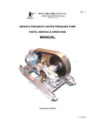
Bronco Pump (Pneumatic) Manual - Parts HeadQuarters Inc
Bronco Pump (Pneumatic) Manual - Parts HeadQuarters Inc
Bronco Pump (Pneumatic) Manual - Parts HeadQuarters Inc
- No tags were found...

You also want an ePaper? Increase the reach of your titles
YUMPU automatically turns print PDFs into web optimized ePapers that Google loves.
Page 2TABLE OF CONTENTSGENERAL INFORMATIONHow to Order Page 3Terms and Conditions Page 4Standard Terms of Sale Page 5Trouble shooting the <strong>Bronco</strong> <strong>Pump</strong>Decreased delivery Accompanied by Rough Operation Page 5Decreased delivery Accompanied by Smooth Operation Page 6Excessive Leaks Page 6Suction Pipe Sizing Page 7Mean Velocity Table Page 8Examples of Suction Pipe Sizing Page 9Volumes Pressure and Horsepower Page 9Examples of Suction Pipe Sizing Page 10Load on the <strong>Pump</strong> and Friction Loss Page 11Volume and Horsepower for all Models Page 11Disassembly of <strong>Bronco</strong> <strong>Pump</strong> Pistons and Yokes Page 12Disassembly of Crankshaft Page 13Replacing Bearings on Crankshaft Page 13Bearing Removal and Mounting Eccentric Bearings Page 14<strong>Bronco</strong> <strong>Parts</strong> Lists Schematics and DrawingsMaximum Operating Capacity Page 15Dimensions Page 15Weights Page 15<strong>Parts</strong> Schematic Page 16<strong>Parts</strong> List showing quantity required Page 17Maintenance and Servicing Page 17<strong>Parts</strong> <strong>HeadQuarters</strong> <strong>Inc</strong> Information Page 1810/31/2005
Page 3GENERAL INFORMATIONHOW TO ORDERA formal purchase order on company letterhead mailed or faxed is satisfactory. Email ordersare satisfactory if full company details are provided. Telephone orders should be confirmed inwriting through mail, fax or Email.The purchase order should contain: the full company name, address, phone and fax numbers(for quick reference or clarification) as well as details to contact the authorizing purchasingpersonnel.Please list on the purchase order: quantity, part number, item description, price, shippingaddress and preferred routing for shipmentsWhen ordering complete machines or major assemblies please furnish complete descriptions ofthe power unit required, sprocket ratios preferred, swivelhead type, chuck jaws sizes, and otherrelative information of standard optional equipment preferred.When ordering pumps please furnish complete description of the power unit required, thesprocket size preferred, the bore size, if a transmission, chain or belt drive is preferred and ifgear reduction is required.Mail or fax orders to:WHERE TO SEND THE ORDER10/31/2005
Page 4TERMS AND CONDITIONSTERMSNORTH AMERICA: Net 30 days on approved creditOverdue payment of invoices incur monthly interest charges of 1.5%)EXPORT SALES : Confirmed irrevocable letter of credit drawn on Canadian BankNet 30 days credit terms available through Canadian EDC guaranteesIf purchasing company has an acceptable EDC credit ratingVisa or MasterCard acceptable for payment with referencesPayment in advance of shipment by wire transfer to Canadian BankDELIVERYMost items are available from stock and you will receive a confirmed order acknowledgementspecifying shipment date. Shipments will be routed by the most direct and economical means oftransportation unless otherwise specified and your order should indicate if partial orders areacceptable.RETURN OF GOODSGoods may be returned with the advance express written permission of <strong>Parts</strong> <strong>HeadQuarters</strong> <strong>Inc</strong>.Goods returned are subject to 25% restocking charges. Special equipment is not returnable.Only new drilling material is returnable. No credit will be issued for used drill material or tools.<strong>Parts</strong> <strong>HeadQuarters</strong> <strong>Inc</strong>. retains the right to inspect and reject any material returned for creditand to deny credit for any goods judged not to be suitable for resale.GENERAL INFORMATIONPrices and specifications listed are subject to change at any time without notice.Quotations for products are dated and valid for no more than 60 days from the date shown.All prices are F.O.B. <strong>Parts</strong> <strong>HeadQuarters</strong> <strong>Inc</strong> warehouse, Burlington, Ontario, Canada, L7L 5H9.Federal and Provincial taxes where applicable are extra and charged on PHQ invoices.The cost of exporting documents and insurance may be added and shown on PHQ invoices.Prepaid freight and handling charges may be added and shown on PHQ invoices.10/31/2005
Page 510/31/2005
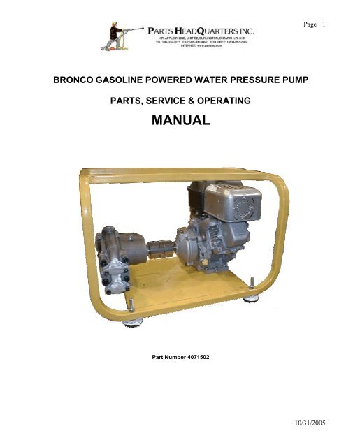
Page 6`Water <strong>Pump</strong>s(Reference: Plate 1586e)General InstructionsDRIVEJKS <strong>Bronco</strong> pumps operate well in either direction of rotation. The main bearings are designed to withstand anyloads that may be imposed on the shaft through a flexible coupling, V-belt or roller chain drive. Solid couplings aretoo rigid and are not acceptable.LUBRICATIONNew pumps are lubricated prior to testing and shipping. Re-lubricate according to instructions on the pump body.COLD WEATHERFreezing can damage your pump. Pour anti-freeze into pump inlet and turn pump a few revolutions to circulate it.Always turn pump by hand before operating in cold weather to check for ice behind pistons before operation.CAUTION – If the pump is frozen do not attempt to thaw it out by pouring boiling hot water over the pump body.Sudden temperature fluctuations could cause further damage and could crack the ceramic cylinder liners.STORAGEBefore placing the <strong>Bronco</strong> pump into extended storage, always flush pump out with lubricant and seal openings.MATERIAL HANDLEDJKS <strong>Bronco</strong> pumps are not recommended for the pumping of fluids at temperatures in excess of 150Fahrenheit.Aluminium pump models are not recommended for, use with caustic fluids, due to possible chemical reactions.When pumping caustic solutions cast iron pumps are recommended. Generally, when in doubt, you should checkwith PHQ and your chemical manufacturer to ascertain compatibility of chemical fluids and pump materials.Solid particles larger than 1/16 inch can hamper valve action. Particles larger than 1/4 inch can lodge in pumppassageways. A suction strainer is provided with the pump to prevent coarse particles from entering the pump.Sudden temperature fluctuations of greater than 100-Fahrenheit degrees in any fluid being pumped will crack theceramic cylinder liners in the <strong>Bronco</strong> pump.LEAKAGEHeavy-duty piston cups may leak during the first few hours of operation until properly seated. If available, useTeflon lubricant when installing new cups. Otherwise keep cylinders and piston components clean and free ofgrease or other deposits. (Remove excess grease from the front bearing cavity). <strong>Pump</strong> cups running on hot waterwill leak if subjected to cold water, but will dry up again when returned to hot operation.10/31/2005
Page 7INSTALLATION OF PUMPCavitations due to undersized or long suction lines are a leading cause of premature pump failure. If the new pumpis noisy or performs below stated volume, the pump may be cavitating. PHQ staff will be pleased to assist youthrough any problems encountered during pump installation and start up.For best pump performance:1. Install a relief valve in the discharge piping.2. Use the shortest possible suction lines and make sure a strainer prevents particle entry.3. Use adequate bore size in the suction hose and fittings, as calculated in following section "Sizing SuctionLines". Pipe or hose that is larger than the pump inlet may be required.4. Provide a positive head on suction where possible.5. Use the lowest pump speed that will give the required output volume for your requirements.6. Avoid the use of chemicals that will deposit in suction lines.7. Avoid high temperatures. If hot fluid is required, it should be heated after passing through the pump.8. Avoid high-pressure settings if a lower pressure will do the job.9. Scale deposits resulting from pumping heated hard water will cause premature wear of the piston cups andvalve seats. In this instance water-softening agent is recommend.10/31/2005
Page 8Trouble ShootingA. Decreased Delivery Accompanied By Rough Operation.Possible Causes:1. Air entering suction piping2. Air leaking past piston cups3. <strong>Pump</strong> valve malfunction4. Plugged or restricted pump suction passages5. Plugged or constricted suction piping (suction valve not fully open)6. Collapsed suction hose.Checking Procedure:1. Examine the valve seats for wear and pitting.2. Arrange a barrel or tank and a hose from pump outlet or regulating relief valve by-pass outlet to collect theentire pump discharge. Measure the time to collect a predetermined volume or, with the barrel or tank on aweigh scale, weigh the results of three or four minutes of pumping. Comparing the measured flow ingallons per minute with the rated capacity for the pump speed3. Examine the water in the barrel or tank for air bubbles while the pump is discharging. If no bubbles areseen and the discharge has definitely decreased, look for plug-ups, worn valve seats or collapsed suctionhose. If bubbles are seen, look for air leaks in the suction piping or for air leaking past the piston cups.These leaks are hard to find because they are leaking 'in' rather than 'out’, however, if arrangements. aremade to put pressure into the suction piping or if new cups smooth out the pump operation, the problem issolved.10/31/2005
Page 9B. Decreased Delivery Accompanied By Smooth Operation.Possible Causes:1. Worn Valve Seats.2. Slipping beltsChecking Procedure:1. Look for worn or pitted valve seats.2. Measure clearance between outer surface of eccentric roller bearing and yoke pads with a feeler gauge.This should not exceed .010"3. Measure pump speeds with a tachometer.Corrective Action1. Renew Worn Valve Seats2. Replace badly worn belts.NOTE. Worn yoke pads will give very noisy operation. Worn yokes or pads should be replaced.C. Excessive Leakage.1. Worn piston cups.2. Loose piston bolts.3. Damaged 'O' Rings.4. Cracked ceramic liners5. Faulty Gaskets.6. Loose Valve caps.7. Loose cylinder head bolts.Checking Procedure and Corrective ActionExamine pistons and cups for wear. Generally a cup will not leak severely until it is torn. The piston should not bemore than .020" out of round.2,6 & 7. Tighten loose piston bolts, cylinder head bolts and valve caps.3&5. Check 'O' Rings and gaskets for breaks.Remove cylinder blocks or cylinder heads and examine ceramic liners for cracks.REPLACE ALL WORN AND DAMAGED PARTSD. Mechanical Trouble.NOTE. Excessive grease leakage results from beat or dented Nylos seals. Damaged seals should be replaced.1. Excessive crankshaft endplay.2. Slack eccentric bearings.Checking Procedure1. Measure crankshaft endplay with a dial indicator, micrometer or feeler gauge. It should be set between.003 inches and .005 inches.2. With end play corrected, turn crankshaft by hand and "feel' for tough main bearings. Check eccentricbeating wear by measuring side play with a dial indicator, micrometer or feeler gauges. It should notexceed .005 inches (Replace worn bearings)10/31/2005
Page 1110/31/2005
Page 15Crankshaft can be bumped out of pump body on a wood block, as shown above, after removal of the piston yokes,as follows:1. Remove the cylinder heads to expose the piston bolts loosen the piston bolts in order to free the yokes.2. Remove the Timken lockout and lock washer. (RP2-4 has solid set collar to be removed). Use TimkenTNO6 & TNO8 lock nut wrenches.Eccentric bearings and inner main bearings are removed, preferably on a hydraulic press, with minimum amount of tooling shown above.(RP2-4 Model <strong>Pump</strong> requires conventional ball bearing or gear puller to remove bearings from pump body).REPLACING BEARINGS ON CRANKSHAFTMain bearings will be complete with integral seal or have separate NILOS metal seal. Metal seals may be damagedin disassembly and must be replaced.1. After Inner Main Bearing and Eccentric Bearings are mounted the shaft is placed into the pump body.2. Drive outer main bearing on shaft using a suitable diameter and pipe as a drift. The drift should comeagainst the inner race of the bearing to avoid damaging the cage.10/31/2005
Page 16Adjusting for endplay is similar to the procedure for the front wheels of an auto. The end play clearance allowance,for JKS <strong>Pump</strong>s is .003" to.005". The Timken Lock nut on Timken equipped pumps may be tightened until the shaftwill not turn. The nut is then backed off slightly. Following this the pump shaft is bumped on a suitable block until itturns freely, as shown above for removing shaft. A method of prying the body while held in a vice at the shaft endcan be arranged. The jaws of die vice must have soft metal shields to protect the shaft from being damaged. A dialindicator bracketed to the pump body with feeler resting on the crankpin will reveal the clearance while prying.After the instructions shown above have been accomplished select the nearest tongue of the lock washer to thegroove of the locknut and bend it into same groove.THE PUMP IS NOW READY FOR ALL OTHER ASSEMBLIES. (SEE THE PUMP ASSEMBLY SHEETS).All bolting should be reasonably snug to avoid leakage.10/31/2005
Page 1710/31/2005
Page 1810/31/2005
Page 1910/31/2005
Page 20MAINTENANCE and SERVICINGCYLINDER HEAD AND VALVE ASSEMBLY:1. Grease all ‘O; Rings to hold them in place during assembly.2. Install D9-117 0 Ring in the groove provided in P43-11 Seat.3. Assemble <strong>Parts</strong> in Cylinder Head in the sequence shown on the <strong>Parts</strong> List Drawing.4. Mount the Cylinder Head Assemblies on the <strong>Pump</strong> as shown on Page 17 of this <strong>Manual</strong>.DRAINING-PROTECT AGAINST FREEZE UP:1. Remove all valve caps (P45-41) and run <strong>Pump</strong> for 10 seconds or pump a suitable Anti-Freeze mixture.PISTON ASSEMBLY:1. If available, use a small amount of Teflon Lubricant on the outer surface of New Piston Cups.2. Assemble Piston <strong>Parts</strong> as Shown in the Drawing.3. Push the Piston Assembly into the Cylinder Liner making sure that the head of the Piston Bolt is at the endof the Cylinder Liner where the Ceramic Liner is flush with the surrounding Steel jacket.4. Coat the outside of the Cylinder Liner with a suitable Anti-Seize Compound.5. Use a suitable Locking Compound on that end of the Piston Bolt that threads into the Yoke Assembly6. Install Piston and Liner Assembly in <strong>Pump</strong>.CRANKSHAFT AND MAIN BEARINGS:1. Refer to Detailed Instructions in the <strong>Manual</strong> for JKS Piston <strong>Pump</strong>s". For <strong>Bronco</strong> <strong>Pump</strong>s keep the endplayclearance as low as is Possible.PISTON CUPS:1. Some minor seepage may occur when the temperature of the fluid pumped is reduced. This seepage willusually stop if the lower temperature is maintained for several hours or, the temperature of the fluid isreturned to the higher level.2. If severe leakage occurs, stop the pump and replace worn parts. Continued operation with excessiveleakage will damage bearings.LUBRICATION:1. See Grease Instruction Decal on <strong>Pump</strong> Cover.RECOMMENDED TORQUE FOR TIGHTENING:10/31/2005
Page 21PHQ was formed twenty years ago to supplypneumatic underground mining equipment,replacement parts and mining hardware.PHQ grew into the manufacturing of completepercussion drills, drill feeds, drill centralizers,remote control panels, mufflers, diamond drills,high pressure pumps, diamond drilling rods,core barrels, adapters and accessories..PHQ cooperates in the research of the use ofwater hydraulic drills, and is working withCANMET and the University of Sherbrooke inanti-vibration dampening for pneumatic drills.PHQ continually strives toward excellencePHQ up-graded our in-house quality system inyear 2003 from ISO9002:94 to ISO9001:2000passing the first audit of the up-graded systemwith no faults whatsoever the first time around.PHQ passed our annual re-registration audit ofour quality system this year in our Burlingtonshop with no faults for the fourth time in a row.PHQ adopted the logo of a miner running apneumatic hand held jackleg drill as thesymbol of our company and in integral part ofthe Logo that we proudly display. It signifiesour commitment to producing pneumaticdrilling equipment for the mining industry.10/31/2005