FP-16 Operation Manual - Berridge Manufacturing Co.
FP-16 Operation Manual - Berridge Manufacturing Co.
FP-16 Operation Manual - Berridge Manufacturing Co.

Create successful ePaper yourself
Turn your PDF publications into a flip-book with our unique Google optimized e-Paper software.
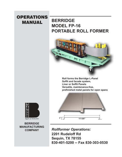
OPERATIONS<br />
MANUAL<br />
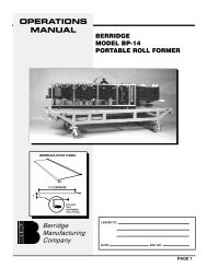
BERRIDGE<br />
MODEL <strong>FP</strong>-<strong>16</strong><br />
PORTABLE ROLL FORMER<br />
Roll forms the <strong>Berridge</strong> L-Panel<br />
Soffit and facade system,<br />
Liner or Soffit Panels<br />
Versatile, maintenance-free,<br />
prefinished metal panels for open spans<br />
1”<br />
11-5/8”<br />
BERRIDGE<br />
MANUFACTURING<br />
COMPANY<br />
Rollformer <strong>Operation</strong>s:<br />
2201 Rudeloff Rd<br />
Sequin, TX 78155<br />
830-401-5200 -- Fax 830-303-0530
BERRIDGE MANUFACTURING COMPANY<br />
<strong>FP</strong>-<strong>16</strong> PORTABLE ROLLFORMER OPERATIONS MANUAL<br />
OVERVIEW<br />
The <strong>Berridge</strong> Model <strong>FP</strong>-<strong>16</strong> portable rollformer forms the <strong>Berridge</strong> L-Panel in a variety of Rib and<br />
Venting configurations. The <strong>FP</strong>-<strong>16</strong> allows continuous length L-Panels to be formed “On Site”<br />
from pre-finished <strong>Berridge</strong> coil stock.<br />
11 5 8 "<br />
1"<br />
Fig. 1 <strong>Berridge</strong> L-Panel<br />
TRANSPORTING THE <strong>FP</strong>-<strong>16</strong><br />
Never transport the machine without threading a strip of coil through the machine that is long<br />
enough to fully engage all of the roller sets. Following this procedure will keep the rolls from<br />
moving while in transit and becoming scarred or damaged, or shifting out of alignment from<br />
vibration or impacts. Do not transport the rollformer with a coil loaded on the uncoiler.<br />
COIL REQUIREMENTS<br />
<strong>Co</strong>il material used with the <strong>Berridge</strong> Model <strong>FP</strong>-<strong>16</strong> Portable Roll Former must comply with the<br />
following parameters:<br />
Strip Width:………………………..15.875 inches (Nominal <strong>16</strong> inches)<br />
Thickness:……………..................24 Gauge (0.024 Inches)<br />
Type:……………………………….Prefinished galvanized or Galvalume<br />
Maximum Weight:………………..2000 lbs.<br />
Minimum Inside Diameter:………20 inches<br />
Note: Only <strong>Berridge</strong>-supplied coil may be used with the <strong>FP</strong>-<strong>16</strong> Portable Rollformer.<br />
<strong>Co</strong>il from other sources may damage the forming rolls on the machine. If coil from<br />
a source other than <strong>Berridge</strong> is used in the <strong>FP</strong>-<strong>16</strong>, <strong>Berridge</strong> <strong>Manufacturing</strong> may<br />
recall the machine and disassemble and inspect it. A service charge may be<br />
assessed.<br />
Page 1 of 9
BERRIDGE MANUFACTURING COMPANY<br />
<strong>FP</strong>-<strong>16</strong> PORTABLE ROLLFORMER OPERATIONS MANUAL<br />
ELECTRIC POWER REQUIREMENTS<br />
The <strong>FP</strong>-<strong>16</strong> Rollformer may be powered by either an electric drive unit which uses an electric<br />
motor and clutch/brake system to drive the forming rolls, or a hydraulic power unit with a<br />
hydraulic motor for driving the forming rolls. The <strong>FP</strong>-<strong>16</strong>s that are powered with hydraulic<br />
systems still require electric power for the hydraulic system and computer. The performance of<br />
the machine is not affected by the type of power unit used to drive the rollformer.<br />
The electric power requirements for the electric and hydraulic drive systems are below:<br />
Electric Drive System: 240 Volt 20 Amp Single Phase Electric Power<br />
Hydraulic Drive System: Requires both 240 Volt 30 Amp Single Phase and 120 Volt 15<br />
Amp Electric Power (120 volt service powers computer)<br />
Note: The use of portable generators is not recommended with the <strong>FP</strong>-<strong>16</strong><br />
Rollformer. Portable generators may damage the computer control system and<br />
electric motor.<br />
If extension cords are required, see the table below for sizing:<br />
120 Volt 15 Amp Service (used for computer only)<br />
0-200 FT 12 Gauge Wire<br />
240 Volt 20 Amp and 30 Amp Single Phase Service<br />
0-100 FT 10 Gauge Wire<br />
100-200 FT 8 Gauge Wire<br />
PERFORMANCE and SPECIFICATIONS<br />
Page 2 of 9
BERRIDGE MANUFACTURING COMPANY<br />
<strong>FP</strong>-<strong>16</strong> PORTABLE ROLLFORMER OPERATIONS MANUAL<br />
(overall size and weight includes table, casters, and uncoiler – omitted below for clarity)<br />
WIDTH:<br />
LENGTH:<br />
HEIGHT:<br />
WEIGHT:<br />
FORMING SPEED:<br />
2’ -11”<br />
14’-8”<br />
4’-8”<br />
Electric Drive: 3240 lbs.<br />
48 Lineal Feet per Minute<br />
Hydraulic Drive: 3650 lbs.<br />
Fig. 2 <strong>FP</strong>-<strong>16</strong> Main <strong>Co</strong>mponents<br />
A:<br />
B:<br />
C:<br />
D:<br />
Perforation Rollers<br />
Stiffening Rib Assembly<br />
Shear<br />
Drive Roll Brake (for stopping<br />
coil feed after shearing last panel)<br />
E:<br />
F:<br />
G:<br />
Feed-In Guides<br />
Encoder (<strong>Co</strong>unter) for <strong>Co</strong>mputer<br />
Forming Rolls<br />
Page 3 of 9
BERRIDGE MANUFACTURING COMPANY<br />
<strong>FP</strong>-<strong>16</strong> PORTABLE ROLLFORMER OPERATIONS MANUAL<br />
OPERATING INSTRUCTIONS<br />
Loading <strong>Co</strong>il<br />
A.<br />
B.<br />
C.<br />
D.<br />
E.<br />
F.<br />
G.<br />
H.<br />
Lock all four casters.<br />
Rotate the eccentric tubes on the uncoiler by loosening the nuts on top of the<br />
tubes. Then rotate the tubes inward to accept the coil.<br />
Unlock the locking bar on the coil lifter arm, fold the legs inward, and drop inside<br />
of coil.<br />
When lifting feet clear the bottom of the coil, spread the legs apart, swing down<br />
the locking arm, and lock the arm in place. The coil should now be resting on the<br />
two lifting feet of the coil lifter arm.<br />
Using a forklift or other lifting apparatus with a minimum load capacity of 2000<br />
lbs., pick up the coil by means of a chain (sized to accommodate the load)<br />
attached to the lifting ring at the top of the coil lifter arms. Stay to one side of the<br />
coil and do not walk beneath it.<br />
Center the coil over the uncoiler, and slowly lower it down onto the uncoiler with<br />
all 4 uncoiler tubes inside the coil.<br />
When the coil is safely seated on the uncoiler arms, rotate the uncoiler tubes out<br />
to make contact with the inside of the coil. Lock the locking nuts on the uncoiler<br />
tubes.<br />
Unlock the locking bar on the coil lifter, swing the legs in, and lift the coil lifter out<br />
of the coil.<br />
Fig. 3 <strong>Co</strong>il Lifter Arms<br />
A:<br />
B:<br />
C:<br />
Lifting Ring<br />
Lifting Feet<br />
Locking Bar<br />
Page 4 of 9
BERRIDGE MANUFACTURING COMPANY<br />
<strong>FP</strong>-<strong>16</strong> PORTABLE ROLLFORMER OPERATIONS MANUAL<br />
OPERATING INSTRUCTIONS (<strong>Co</strong>nt.)<br />
Feeding <strong>Co</strong>il Into the Rollformer: Electric Drive System<br />
A.<br />
B.<br />
C.<br />
D.<br />
E.<br />
F.<br />
Pull the Drive Roll Release (Fig. 2 Item D) forward to lock the first station drive<br />
rolls together.<br />
Feed the leading edge of the coil into the Feed-In Guides on the rollformer (Fig. 2<br />
Item E) and up to the first station rollers.<br />
The drum switch, located near the bottom of the rollformer and to the left of the<br />
shear (Fig. 2 Item C), controls the drive direction of the rollers. Put the switch in<br />
the forward position.<br />
The green jog button is located above the shear. In the same control box as the<br />
jog button is a toggle switch with two positions: “<strong>Manual</strong>” and “<strong>Co</strong>mputer”. Put the<br />
toggle switch in the “<strong>Manual</strong>” position.<br />
Press the green jog button to engage the rollers. Carefully feed the coil into the<br />
first station rollers, pulling lightly on the top edge of the coil if necessary for it to<br />
enter the first station rollers. Keep hands away from the rollers inside the<br />
plexiglass and the shear station.<br />
<strong>Co</strong>ntinue feeding the coil until the leading edge is just past the shear. Release the<br />
green button to stop the coil, and lift the shear to cut the leading edge of the coil.<br />
Note: To begin production using the computer, switch the toggle switch to<br />
the “<strong>Co</strong>mputer” position. See the <strong>Co</strong>mputer Operating Instructions<br />
provided with the computer for programming and operation guidelines.<br />
Feeding <strong>Co</strong>il Into the Rollformer: Hydraulic Drive System<br />
A.<br />
B.<br />
C.<br />
D.<br />
E.<br />
F.<br />
Pull the Drive Roll Release (Fig. 2D) forward to lock the first station drive rolls<br />
together.<br />
Feed the leading edge of the coil into the Feed-In Guides on the rollformer (Fig.<br />
2E) and up to the first station rollers.<br />
The Power Switch is located near the exit end of the rollformer on the operator<br />
side, in a gray electrical enclosure. Push the On button to turn on the hydraulic<br />
system.<br />
The computer is used to jog the rollformer as follows:<br />
A. Turn the center switch on the right side of the computer to the<br />
“<strong>Manual</strong>” position.<br />
B. Turn the bottom switch to the “Forward” position and the rollers will<br />
start turning. Release the switch to stop the machine (switch will spring<br />
back to the center “Off” position). Turn switch to the “Reverse” position<br />
to reverse the feed direction.<br />
Using the computer, carefully jog the material into the rollformer until the leading<br />
edge of the coil is just past the shear.<br />
Press the “Shear” button on the computer to cut the end of the coil. Keep hands<br />
away from the rollers and shear station during this operation.<br />
Note: To begin production using the computer, see the <strong>Co</strong>mputer<br />
Operating Instructions provided with the computer for programming and<br />
operation guidelines.<br />
Page 5 of 9
BERRIDGE MANUFACTURING COMPANY<br />
<strong>FP</strong>-<strong>16</strong> PORTABLE ROLLFORMER OPERATIONS MANUAL<br />
SETUP AND CONFIGURATION<br />
The <strong>FP</strong>-<strong>16</strong> is a “fixed width” machine – it runs coil that is 15.875” (15 7/8” – Nominal <strong>16</strong>”) wide.<br />
The width is fixed and cannot be adjusted. The feed-in guides and interior guide rolls are factory<br />
set to produce a panel of the correct profile.<br />
The <strong>FP</strong>-<strong>16</strong> can be set to form a panel with the following configurations:<br />
A. Smooth panel pan<br />
B. Panel pan with 2 Stiffening Ribs<br />
C. Panel pan with 2 rows of Perforations (Vents)<br />
D. Panel pan with 1 Stiffening Rib and 2 rows of Perforations (Vents)<br />
The instructions below explain the installation procedures for Stiffening Ribs and Perforations.<br />
Stiffening Ribs<br />
The Stiffening Rib rollers are a self-contained assembly. The rollers are mounted on a frame<br />
which bolts to the frame of the rollformer.<br />
To remove the Stiffening Ribs, simply remove the entire assembly from the rollformer. Do not<br />
attempt to disassemble part of the assembly because this could change the clearance between<br />
the rollers and affect the appearance of the panel. See the section below for detailed<br />
instructions.<br />
Installing the Stiffening Rib Assembly<br />
A.<br />
B.<br />
C.<br />
D.<br />
E.<br />
F.<br />
Remove the clear lexan cover on the operator side of the machine.<br />
Locate the mounting location for the Stiffening Rib Assembly (see Fig. 4 below).<br />
The two vertical framing members in the machine (Fig. 4 Item C - operator side<br />
and motor side) will have threaded holes located near the top and bottom of<br />
each member.<br />
Insert the stiffening rib assembly oriented as shown in Fig. 5 below (the<br />
direction of material flow should be right to left). The male die should be on the<br />
operator side and the female on the motor side, causing the rib to be indented<br />
toward the motor side of the machine.<br />
Line up the mounting holes in the Stiffening Rib assembly with the threaded<br />
holes in the vertical framing members.<br />
Using the bolts supplied with the Stiffening Rib Assembly (Fig. 5 Item B), bolt<br />
the Assembly in place.<br />
Replace the operator side lexan cover. Run a test panel to ensure the ribs are<br />
forming correctly.<br />
Page 6 of 9
BERRIDGE MANUFACTURING COMPANY<br />
<strong>FP</strong>-<strong>16</strong> PORTABLE ROLLFORMER OPERATIONS MANUAL<br />
Stiffening Ribs (<strong>Co</strong>nt.)<br />
Fig. 4 Stiffening Rib Location<br />
Fig. 5 Stiffening Rib Assembly<br />
A. Stiffening Rib Assembly<br />
B. Stiffening Rib Mounting Bolts<br />
C. <strong>FP</strong>-<strong>16</strong> Vertical Framing Members<br />
Perforations (Venting)<br />
The <strong>FP</strong>-<strong>16</strong> Rollformer is fitted with a set of perforating rollers near the exit end of the machine.<br />
Perforations are partially punched slots through the pan of the panel, allowing air flow through<br />
the panel for vented soffits and similar applications. Perforations are installed in the pan of the<br />
panel by shifting the male perforating rollers toward the female set of rollers (toward the motor<br />
side of rollformer) until the correct die clearance is achieved.<br />
Important!!!: It is critical that the perforation rollers be setup correctly to avoid<br />
damaging the panel and possibly destroying the rollers. Read the instructions<br />
below carefully before attempting to adjust the perforation rollers.<br />
Page 7 of 9
BERRIDGE MANUFACTURING COMPANY<br />
<strong>FP</strong>-<strong>16</strong> PORTABLE ROLLFORMER OPERATIONS MANUAL<br />
Perforations (Venting) – (<strong>Co</strong>nt.)<br />
Installing the Perforations (Vents)<br />
A.<br />
B.<br />
C.<br />
D.<br />
E.<br />
F.<br />
G.<br />
H.<br />
I.<br />
Remove the operator side clear lexan cover.<br />
Loosen the top and bottom Lock-Down Bolts (A).<br />
Loosen the top and bottom Outer Adjustment Bolts (B). The Outer Adjustment<br />
Bolts are used to pull the Male Perforation Rollers (D) away from the Female<br />
Perforation Rollers (E) (disengage the rollers). The Inner Adjustment Bolts are<br />
used to push the Male Perforation Rollers toward the Female Perforation<br />
Rollers (engage).<br />
After loosening the Outer Adjustment Bolts on both the top and bottom of the<br />
rollformer, turn the Inner Adjustment Bolt clockwise, causing the Male<br />
Perforation Rollers to move toward the Female Perforation Rollers.<br />
Note: The top and bottom MUST be moved together. Move the bottom<br />
no more than 1/8”, then move the top 1/8”. This will keep the male roller<br />
set parallel to the female roller set. Do not move the top and bottom<br />
independently more than 1/8”, or the rollers could become jammed<br />
between the top and bottom plates of the rollformer.<br />
When the protrusions on the male rollers reach the slots in the female rollers,<br />
use a Feeler Gauge to set the clearance between the rollers (see Fig. 7 below).<br />
The clearance should be set at about 0.060” at both the top and bottom.<br />
Note: If either the top or bottom adjustment is moved, the clearance<br />
between BOTH the top and bottom roller sets must be re-checked with<br />
the feeler gauge. Moving the top or bottom affects both the top and<br />
bottom clearances.<br />
After setting the top and bottom clearances, tighten the Outer Adjustment Bolts.<br />
Check the clearances again before proceeding to make sure the rollers did not<br />
shift. If the clearances are not 0.060”, continue with the adjustments until the<br />
correct clearances are reached.<br />
After confirming the clearances are correct and the Inner and Outer Adjustment<br />
Bolts are tight, tighten the Lock-Down Bolts to hold the rollers in place.<br />
Run a panel and examine the perforations. Make sure all perforations are<br />
correctly punched and the metal is cut on both sides of each strip of<br />
perforations. Also examine the aesthetics of the panel under good lighting<br />
conditions to ensure the panel is being formed correctly. If the panel is not<br />
acceptable, check the clearances between the top and bottom roller sets to<br />
make sure the proper clearance is set. The clearance might need to be adjusted<br />
slightly tighter or looser than the 0.060” starting point.<br />
To remove perforations from the panel (disengage the perforation rollers),<br />
reverse the above process to move the male rollers away from the female<br />
rollers.<br />
Note: When disengaging the rollers, make sure there is at least ¼” of<br />
clearance between the male and female rollers to avoid interfering with<br />
the panel.<br />
Page 8 of 9
BERRIDGE MANUFACTURING COMPANY<br />
<strong>FP</strong>-<strong>16</strong> PORTABLE ROLLFORMER OPERATIONS MANUAL<br />
Perforations (Venting) – (<strong>Co</strong>nt.)<br />
Fig. 6 Perforation Forming Station<br />
A. Lock-Down Bolts<br />
B. Outer Adjustment Bolts<br />
C. Inner Adjustment Bolt<br />
D. Male Perforation Rollers<br />
E. Female Perforation Rollers<br />
Note: Only bolts on bottom are<br />
noted, but bolts on top need to be<br />
adjusted also<br />
Fig. 7 Using Feeler Gauge to Set Perforation Clearance<br />
Page 9 of 9