SPA 01
SPA 01
SPA 01

Create successful ePaper yourself
Turn your PDF publications into a flip-book with our unique Google optimized e-Paper software.
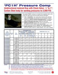
Under Oil Power Pack <strong>SPA</strong> <strong>01</strong><br />
p max up to 250 bar Q max up to 17 L/min<br />
HA 7111<br />
11/2005<br />
Replaces<br />
HA 7111 1/2003<br />
Small compact power packs used in lifting platforms,<br />
ramps and other applications<br />
3 basic hydraulic circuits<br />
Low noise level<br />
High power ratio in relation to envelope dimensions<br />
Tank capacities from 7 to 30 L<br />
Possibility of building up an addition circuit in the form<br />
of horizontal stacking assembly of the size 04 or 06<br />
Functional Description<br />
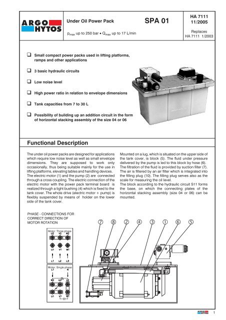
The under oil power packs are designed for applications<br />
which require low noise level as well as small envelope<br />
dimensions. They are supposed to work only<br />
occasionally, thus being suitable mainly for the use in<br />
lifting platforms, elevating tables and handling devices.<br />
The electric motor (1) and the pump (2) are connected<br />
through a cross coupling. The electric connection of the<br />
electric motor with the power pack terminal board is<br />
realized through a tight bushing (4) which is fixed to the<br />
tank cover. The whole drive (electric motor + pump) is<br />
flexibly suspended by means of holder on the lower<br />
side of the tank cover.<br />
Mounted on a lug, which is situated on the upper side of<br />
the tank cover, is block (5). The fluid under pressure<br />
delivered by the pump is led to this block by hose (6).<br />
The filtration of the fluid is provided by suction filter (7).<br />
The air is filtered by an air filter which is integrated into<br />
the filling plug (10). The filling plug serves also as the<br />
scale for measuring the oil level.<br />
The block according to the hydraulic circuit S11 forms<br />
the base, on which the connecting plates of the<br />
horizontal stacking assembly (size 04 or 06) can be<br />
mounted.<br />
PHASE - CONNECTIONS FOR<br />
CORRECT DIRECTION OF<br />
MOTOR ROTATION<br />
<br />
Motor: Three phase<br />
Motor: Single phase<br />
1
HA 7111<br />
Ordering Code<br />
<strong>SPA</strong> <strong>01</strong> - / - - - XXXX/<br />
Under oil power pack<br />
Displacement of the pump<br />
in cm 3<br />
0,8 08<br />
1,2 12<br />
1,6 16<br />
2,1 21<br />
2,5 25<br />
3,3 33<br />
3,6 36<br />
4,4 44<br />
4,8 48<br />
5,8 cm 3 /Um. 58<br />
6,2 cm 3 /Um. 62<br />
7,9 cm 3 /Um. 79<br />
Solenoid voltage<br />
<strong>01</strong>200 12V DC<br />
<strong>01</strong>400 14V DC<br />
02100 21V DC<br />
02400 24V DC<br />
04200 42V DC<br />
04800 48V DC<br />
06000 60V DC<br />
10200 102V DC<br />
20500 205V DC<br />
02450 24V / 50 (60)Hz<br />
11550 115V / 50 (60)Hz<br />
23050 230V / 50 (60)Hz<br />
Type No. - determined by manufactured<br />
Code of the electric motor - see Tab. 1<br />
Type of the block - see page 3<br />
Code of the tank<br />
7 7 L<br />
10 10 L<br />
20 20 L<br />
30 30 L<br />
Technical Data<br />
Flow rate L/min Tab. 1<br />
Working pressure bar Tab. 1<br />
Max. working/peak pressure bar Tab. 1<br />
Tank capacity L 7,10, 20, 30<br />
Type of the pump<br />
external gear pump<br />
Power of the electric motor kW 0,55 to 3<br />
Load factor of the electric motor % 20<br />
Type of the electric motor single phase three phase<br />
Voltage of the electric motor V 230 400<br />
Frequency Hz 50 50<br />
Enclosure type of the electric motor IP 54<br />
Hydraulic fluid<br />
Hydraulic oils of power classes HM, HV to CETOP<br />
RP 91 H in viscosity classes ISO VG 32, 46 and 68<br />
Viscosity range mm 2 /s 20 ... 100<br />
Maximum degree of fluid contamination Class 21/18/15 to ISO 4406 (1999).<br />
Fluid temperature range °C -30 ... +80<br />
Ambient temperature max. °C up to 50<br />
Thread of the connecting ports P, T, M, (A, B) G 1/4<br />
Working position<br />
horizontal<br />
2
Tab. 1<br />
Type of the hydraulic circuit<br />
HA 7111<br />
Code of the electric motor<br />
Code of the pump<br />
08 P2.. 12 P2.. 16 P2.. 21 P2.. 25 P2.. 33 P2..<br />
pmax.** [bar] 250<br />
R.P.M. 400 V kW Q /pn * [l/min] / [bar]<br />
13 0.55 1.5/175 2.0/130 2.6/100 3.1/85 4.2/65<br />
14 0.75 1.9/190 2.5/145 3.0/120 3.9/90<br />
1500<br />
15 1.1 2.1/200 2.8/190 3.3/160 4.4/120<br />
16 1.5 3.2/200 4.2/170<br />
17 2.2<br />
18 3.0<br />
30 0.55 2.2/120 3.2/80 4.3/60 5.6/45 16.7/40 8.9/30<br />
31 0.75 2.2/160 3.2/110 4.3/80 5.6/65 6.7/55 8.9/40<br />
3000<br />
32 1.10 2.2/200 3.2/165 4.3/120 5.6/95 6.7/80 8.9/60<br />
33 1.50 3.2/200 4.3/165 5.6/130 6.7/110 8.9/80<br />
34 2.20 4.2/200 5.5/190 6.6/160 8.7/120<br />
35 3.00 6.4/200 8.5/170<br />
Um./min 230 V kW Q /pn * [l/min] / [bar]<br />
5 0.55 1.6/165 2.1/125 2.7/100 3.2/80 4.3/60<br />
1500<br />
6 0.75 1.6/200 2.1/170 2.8/130 3.3/110 4.4/80<br />
7 1.10 2.8/190 3.3/160 4.4/120<br />
8 1.50 3.3/200 4.4/165<br />
Code of the electric motor 36 P2.. 44 P2.. 48 P2.. 58 P2.. 62 P2.. 79 P2..<br />
pmax.** [bar] 250 200 160<br />
R.P.M. 400 V kW Q /pn * [l/min] / [bar]<br />
13 0,55 4.5/60 5.5/50 6.0/45 7.3/35 7.8/35 9.9/25<br />
14 0,75 4.3/85 5.2/70 5.7/65 6.9/50 7.4/50 9.4/40<br />
1500<br />
15 1,10 4.8/110 5.8/90 6.3/85 7.7/70 8.2/65 10.4/50<br />
16 1,50 4.6/155 5.6/130 6.2/115 7.4/100 8.0/90 10.1/70<br />
17 2,20 5.0/200 5.5/190 6.6/160 7.1/150 9.0/120<br />
18 3,30 5.9/200 7.1/200 7.6/190 9.7/150<br />
30 0,55<br />
31 0,75 9.7/35<br />
3000<br />
32 1,10 9.7/55 11.8/45 12.9/40 15.6/35<br />
33 1,50 9.7/75 11.8/60 12.9/55 15.6/45 16.7/40<br />
34 2,20 9.5/110 11.6/90 12.7/85 15.3/70 16.4/65 20.9/50<br />
35 3,00 9.3/155 11.3/125 12.4/115 15.0/95 16.0/90 20.4/70<br />
R.P.M. 230 V kW Q /pn * [l/min] / [bar]<br />
5 0,55 4.7/55 5.7/45 6.2/40 7.5/35 8.0/30 10.2/25<br />
1500<br />
6 0,75 4.8/75 5.9/60 6.4/55 7.7/45 8.3/45 10.5/35<br />
7 1,10 4.8/110 5.9/90 6.4/80 7.7/70 8.5/65 10.5/50<br />
8 1,50 4.8/150 5.9/120 6.4/110 7.7/95 8.5/85 10.5/70<br />
*pn. - nominal pressure = the highest working pressure allowed without time restriction<br />
** pmax. - maximum pressure = maximum pressure allowed for a short time - max. 20s<br />
The hydraulic circuit S11.0 enables the power pack to be used as a simple pressure supply for general applications with<br />
the possibility to build up additional hydraulic circuits in the form of horizintal stacking assemblies of the size 04 or 06.<br />
Should the power pack be run for longer time periods, it is necessary to take the load factor of the electric motor into<br />
account.<br />
The hydraulic circuit S14.N and S24.N enable the power pack to be used as pressure supply for lifting platforms and<br />
other devices, in which the mass of the system provides returning into the basic position. The shuf-off valve (A) enables<br />
emergency lowering of the device, should a disconnection of the supply voltage occur.<br />
The hydraulic circuit S14.N comprises a flow control valve VSK2 (B) which is adjustable only in a certain range (see<br />
cataloge VSK2 - HA 5121). The valve is accessible after removing the block from the tank cover. If not otherwise required, a<br />
valve VSK2 is mounted into the block. The stabilized flow rate of this valve corresponds with the respective flow rate of the<br />
power pack (see Tab. 1).<br />
The hydraulic circuit S24.N comprises a throttle valve VSV1-06 (C) without pressure compensation. This valve is<br />
accessible from outside of the block.<br />
3
HA 7111<br />
Valve Dimensions<br />
Dimensions in millimeters<br />
Steel tank<br />
2xM10-6H deep10<br />
75<br />
A4 61<br />
Example of horizontal stacking assembly<br />
- possible only with hydraulic circuit S11.0<br />
E - according to the elements used,<br />
see datasheet 5021, 5023, 5051, 5091<br />
F - Size 04=40 mm<br />
Size 06=50 mm<br />
G - Size 04=79 mm<br />
Size 06=92 mm<br />
G E 50<br />
PT<br />
11 11<br />
F<br />
F<br />
60<br />
F<br />
40<br />
A2<br />
F<br />
F<br />
Throttle valve VSV1-06 (C)<br />
Block S24.N Block S14.N Block S11<br />
2xM8-6H deep16<br />
19<br />
2xG1/4 deep13<br />
T<br />
34<br />
72<br />
A3<br />
T<br />
P<br />
M<br />
P<br />
A1 43.5<br />
Valve for emergency lowering of the device (A)<br />
Plastic tank<br />
A1<br />
A3<br />
MAX<br />
MIN<br />
A4<br />
4<br />
Code of the tank<br />
<br />
<br />
Tank capacity in<br />
L<br />
A1<br />
mm<br />
10 (sheet) 10 440 220 200 174<br />
20 (sheet) 20 500 220 260 214<br />
30 (sheet) 30 500 220 260 294<br />
7 (plastic) 7 4<strong>01</strong> - 196 223<br />
Caution!<br />
The packing foil is recyclable.<br />
The technical information regarding the product presented in this catalogue is for descriptive purposes only. It should<br />
not be construed in any case as a guaranteed representation of the product properties in the sense of the law.<br />
ARGO-HYTOS a. s. CZ - 543 15 Vrchlabí<br />
Tel.: +420-499-403111, Fax: +420-499-403421<br />
E-mail: sales.cz@argo-hytos.com<br />
www.argo-hytos.com<br />
250 100<br />
A2<br />
mm<br />
A3<br />
mm<br />
A4<br />
mm


![[PDF] DBBV FL/S9 Flange Mount](https://img.yumpu.com/10899396/1/190x245/pdf-dbbv-fl-s9-flange-mount.jpg?quality=85)