PVS Series Variable Volume Piston Pumps - Applied Hydraulic ...
PVS Series Variable Volume Piston Pumps - Applied Hydraulic ...
PVS Series Variable Volume Piston Pumps - Applied Hydraulic ...
- No tags were found...

You also want an ePaper? Increase the reach of your titles
YUMPU automatically turns print PDFs into web optimized ePapers that Google loves.
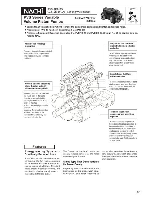
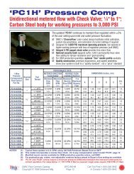
Pressure Compensation Type<strong>PVS</strong>-0B-8N*-E30Installation Dimension DrawingCross-sectional Drawing33 34 27 17 22 25 16 20 10 38 35 28 15 12 11 24 26 21 184039373629253019144Manual mode: standard typeList of Sealing PartsParts marked by an asterisk "*" are not available on the market.Consult your agent.Typical characteristics at hydraulic operating fluid kinematic viscosity of 32 mm 2 /sEfficiency Curves Pressure-Flow Curves Input Power CurvesPerformance Curves6971381 31 32233Part No. Part Name Part No. Part Name Part No. Part Name1234567891011121314BodyCaseShaftCylinder barrelValve plate<strong>Piston</strong>ShoeShoe holderBarrel holderSwash plateThrust bushSpring holderGasketSpring C1516171819202122232425262728Pump capacity q cm 3 /revcm 3 /revRelationship between flow rateadjustmelength ( ) and pump capacity (q)108643 Flow rate adjustment range25 1015Flow rate adjustment length mmSpring SControl pistonGuide pinParallel keyRetainerNeedleBall bearingNeedle bearingOil sealSnap ringSnap ringSnap ringO-ringO-ring<strong>PVS</strong>-0B-8N -30Set a flow rate adjustment length withinthe above range. Oil will leak if the pumpis operated below the adjustment rangelower limit.293031323334353637383940Parallel pinSpring pinHexagon socket head boltCross-recessed countersunkhead screwHexagon socketset screwHexagon nutHexagon plugMetal plugNameplateLubrication port plateCAUTION plateRivetPart<strong>PVS</strong>-0B-8Part Name Q'tyNo.SizeRemarks13 Packing 1 PS46-100000 3 Bond23 Oil seal 1 TCV-254511 N.O.K27 O-ring 1 1B-P9 JIS B 240128 O-ring 1 1B-P11 JIS B 2401Input Power at DeadheadNoise LevelP-5
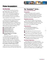
Installation Dimension Drawing<strong>PVS</strong>-1B- 16 N*-E13 (Side Port Type)22The relation between flow adjustinglength (r) and pump displacement(q)Pump Displacement<strong>PVS</strong>-1B- 16 N*-Z13 (Axial Port Type)22Cross-sectional DrawingPart No. Part Name Part No. Part Name3119342923403641 16 17 35 6 72 5 26 14 4 2038915 21 39 308 13 10 1122 12 2833 1 3225243182737123456789101112131415161718192021BodyCaseShaftCylinder barrelValve plate<strong>Piston</strong>ShoeShoe holderBarrel holderSwash plateThrust bushSeal holderGasketSpring CSpring SControl pistonNeedleKeyNutRetainerPlug2223242526272829303132333435363738394041Ball bearingNeedle bearingOil sealSnap ringSnap ringSnap ringO-ringO-ringO-ringPinHexagon socket head boltCross-recessed countersunkhead screwHexagon socket set screwMetal plugNameplateCAUTION plateSpring holderLubrication port plateRivetGuide pinList of Sealing PartsPart No. Name Q'ty Size Remarks13 Gasket 1 PS46-101000 Nihon Gasket24 Oil seal 1 TCN-254511 N.O.K28 O-ring 1 1B-G55 JIS B 240129 O-ring 1 1B-P9 JIS B 240130 O-ring 1 1B-P14 JIS B 2401Parts marked by an asterisk "*" are not available on the market.Consult your agent.P-6
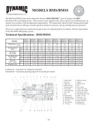
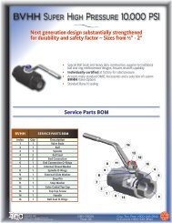
Performance CurvesTypical characteristics at hydraulic operating fluid kinematic viscosity of 32 mm 2 /s<strong>PVS</strong>-1B-16N*-(Z)-E13Efficiency CurvesOil ISO VG 32 Oil temp. 50°C (122°F)Pressure-Flow CurvesInput Power CurvesInput Power at Deadhead Noise Level Oil Temperature Rise CurvesPerformance Curves<strong>PVS</strong>-1B-22N*-(Z)-E13Typical characteristics at hydraulic operatingfluid kinematic viscosity of 32 mm 2 /sOil ISO VG 32 Oil temp. 50°C (122°F)Efficiency CurvesPressure-Flow CurvesInput Power CurvesInput Power at DeadheadNoise LevelP-7
Response PerformanceTest CircuitPiping volume 400 cm 3Qt1Pressure MPat2PsM0MLegendMPaFC(Q=0)14MPa1MPa(Q=MAX)SOL ONSOL OFF1MPaSOL OFFTime sModel No.Response Time (s) Surge Pressure MPa{kgf/cm 2 }t1 t2 PS<strong>PVS</strong>-0B-8 0.03 ~ 0.04 0.04 ~ 0.06 12 ~ 4{20.4 ~ 40.8}<strong>PVS</strong>-1B-16 0.05 ~ 0.06 0.07 ~ 0.08 14 ~ 7{40.8 ~ 71.4}<strong>PVS</strong>-1B-22 0.05 ~ 0.06 0.07 ~ 0.08 15 ~ 8{51 ~ 81.6}<strong>PVS</strong>-2B-35 0.05 ~ 0.06 0.05 ~ 0.07 16 ~ 9{61.2 ~ 91.8}<strong>PVS</strong>-2B-45 0.05 ~ 0.06 0.05 ~ 0.07 16 ~ 9{61.2 ~ 91.8}Response performance changes according to pipe volume and size.Use an anti-surging valve to prevent surge voltage.Pressure Compensator1211102351413194687Part No. Part Name Part No. Part Name1234567BodySpoolHolderPlungerSpringRetainerPressure adjusting bolt891011121314NutO-ringO-ringO-ringPlugPlugMounting boltList of Sealing PartsPartSizeName Q'tyNo.For 0B, 1B, 2B9 O-ring 1 1A-P1410 O-ring 3 1B-P611 O-ring 1 1B-P10Note) O-ring 1A/B-** refers to JIS B2401-1A/B.P-10
Solenoid Cutoff Control TypeExplanation of model No.: <strong>PVS</strong>– 1 B – 16 R 2 S 1 –E13P-Q Characteristics<strong>PVS</strong>-1B- 16 R* A *-E1322 SPump size 1, 2Installation Dimension DrawingSolenoid power supply 1: AC110-115V2: AC220-230V3: DC12V4: DC24VSolenoid specifications A: SA-G01S: SS-G01Pressure adjustment range0: 2- 3.5MPa {286-500psi}1: 2- 7MPa {286-1000psi}2: 3-14MPa {429-2000psi}3: 3-21MPa {429-3000psi}RAS : Solenoid cutoff controlMax. pump capacity (cm 3 /rev)Nominal 16, 22, 35, 45 (in 3 /rev 1.0, 1.3, 2.1, 2.8)Pump capacity qcm 3 /revSOL"OFF"Discharge pressure P MPaSOL"ON"199.8(7.86)42(1.65)Pressure adjustingscrew(at solenoid ON)Flow rate adjustingscrew55(2.16)47.5 22 ±0.2 1.877( 1.862 )4–M10x16SOL bφ24(0.94)Drain port3/8"SAE22 ±0.2( 0.8740.854)12.5(0.49)158(6.22)181(7.12)NACHI77(3.03) 49.5(1.94)47.4(1.86) 6(0.23)43(1.69)25.4(1.00)–0.036φ 19.05 ( )Key width04.76 –0.012( 0.1870.186)5(0.19)–0.021 0.7500.749–0.0321.2 ( )–0.25 0.8340.824–0.036 φ 82.6 –0.071 ( 3.249 )108(4.25)11(0.43)Discharge portSAEJ518b-3/4106.4(4.18)124(4.88)130(5.11)Differential pressureadjusting screw(adjustment forbidden)Lubricationport3(0.11)82(3.22)137(5.39)52(2.04)213(8.38)(SS-G01)177(6.93)(SA-G01)Suction portSAEJ518b-1<strong>PVS</strong>-2B- 35 R* A *-E13, E2045 S317(12.48)(MAX)45(1.77)Pressure adjustingscrew(at solenoid ON)Lock nutFlow rate adjustingscrew69.5(2.73)4–M10x1652.4 22 ±0.2 2.070( 2.055 )SOL bφ28(1.10)NACHI1.03926.2 22 ±0.2 ( 1.023)15(0.69)192(7.55)222(8.74)Pilot port1/4"SAEDrain port1/2"SAEDifferential pressureadjusting screw(adjustment forbidden)88(3.46) 60(2.36)6(0.23)53(2.08)38(1.49)Key width4.76 6.3 +0.015–0.010( 0.2480.247)3(0.11)ABφ 101.6 82.6 –0.051 0 ( 4.0003.997 )90.5(3.56)Discharge portSAEJ518b-1144(5.66)146(5.74)172(6.77)Differential pressureadjusting screw(adjustment forbidden)Lubrication port13(0.51)104(4.09) 3(0.11)172(6.77)65(2.55)194.5(7.65)(SA-G01)230.5(9.07)(SS-G01)Suction portSAEJ518b-11/4in 3 /rev2.12.8PressureRange0 30 23Design ANo.B13D φ 22.23 22 –0.021 00 ( 0.8750.843)24.922 –0.5 00 ( 0.9800.960)20D φ 25.585 22 –0.025 00 ( 0.9990.998)27.85 22 –0.25 00 ( 1.0961.086)❚The coil surface temperature increases if this pump is kept continuously energized.Do not touch the surface of the coil directly with your hands.P-13
2-pressure Control TypeExplanation of model No.: <strong>PVS</strong>– 1 B – 16 W 2 S 1 – E13Pump size 1, 2Solenoid power supply 1: AC110-115V2: AC220-230V3: DC12V4: DC24VSolenoid specifications A: SA-G01S: SS-G01Pressure adjustment range0: 2- 3.5MPa {286-500psi}1: 2- 7MPa {286-1000psi}2: 3-14MPa {429-2000psi}3: 3-21MPa {429-3000psi}WAS : 2-pressure controlMax. pump capacity (cm 3 /rev)Nominal 16, 22, 35, 45 (in 3 /rev 1.0, 1.3, 2.1, 2.8)P-Q CharacteristicsPump capacity qcm 3 /revSOL"OFF"SOL"ON"P1 P2Discharge pressure P MPaInstallation Dimension Drawing<strong>PVS</strong>-1B- 16 W* A *-E1322 S42(1.65)Pressure adjustingscrew(at solenoid OFF)Flow rateadjusting screw55(2.16)47.5 22 ±0.2 1.877( 1.862 )4–M10x16SOL bφ24(0.94)22 ±0.2( 0.8740.854)12.5(0.49)158(6.22)181(7.12)NACHI77(3.03)Drain port3/8"SAEPressure adjusting screw(at solenoid ON)49.5(1.94)6(0.23)43(1.69)25.4(1.00)–0.036φ 19.05 ( )Key width04.76 –0.012( 0.1870.186)5(0.19)–0.021 0.7500.749–0.0321.2 ( )–0.25 0.8340.824–0.036 φ 82.6 –0.071 ( 3.249 )127(5.00)11(0.11)Discharge portSAEJ518b-3/4106.4(4.18)124(4.88)130(5.11)Differential pressureadjusting screw(adjustment forbidden)Lubrication port3(0.11)82(3.22)137(5.39)52(2.04)231(9.09)(SS-G01)195(7.69)(SA-G01)Suction portSAEJ518b-1<strong>PVS</strong>-2B- 35 W* A *-E13, E2045 SPressure adjustingscrew(at solenoid OFF)Lock nutFlow rate adjustingscrew69.5(2.73)4–M10x1652.4 22 ±0.2 2.070( 2.055 )SOL bφ28(1.10)317(12.48)(MAX)Pilot port pp1/2"SAEDrain port1/2"SAEPressure adjustingscrew (at solenoid ON)Differential pressureadjusting screw(adjustment forbidden)88(3.46) 60(2.36)6(0.23)Key width4.76 6.3 +0.015–0.010( 0.2480.247)1.03926.2 22 ±0.2 ( 1.023)15(0.59)192(7.55)222(8.74)NACHI53(2.08)38(1.49) 3(0.11)ABφ 101.6 82.6 –0.051 0 ( 4.0003.997 )90.5(3.56)Discharge portSAEJ518b-145(1.77)144(5.66)146(5.74)172(6.77)Differential pressureadjusting screw(adjustment forbidden)Lubrication port13(0.51)104(4.09) 3(0.11)172(6.77)65(2.55)212.5(8.36)(SA-G01)248.5(9.78)(SS-G01)Suction portSAEJ518b-11/4in 3 /rev2.12.8PressureRange0 30 23Design ANo.B13D φ 22.23 22 –0.021 00 ( 0.8750.843)24.922 –0.5 00 ( 0.9800.960)20D φ 25.585 22 –0.025 00 ( 0.9990.998)27.85 22 –0.25 00 ( 1.0961.086)❚The coil surface temperature increases if this pump is kept continuously energized.Do not touch the surface of the coil directly with your hands.P-14
2-pressure, 2-flow rate Control Type w/ Solenoid CutoffExplanation of model No.: <strong>PVS</strong>– 1 B – 16 RQ 2 S 1 –Pump size 1, 2E13Solenoid power supply 1: AC110-115V2: AC220-230V3: DC12V4: DC24VSolenoid specifications A: SA-G01S: SS-G01Pressure adjustment range0: 2- 3.5MPa {286-500psi}1: 2- 7MPa {286-1000psi}2: 3-14MPa {429-2000psi}3: 3-21MPa {429-3000psi}RQAS: 2-pressure, 2-flow rate control w/solenoid cutoffMax. pump capacity (cm 3 /rev)Nominal 16, 22, 35, 45 (in 3 /rev 1.0, 1.3, 2.1, 2.8)P-Q CharacteristicsPump capacity qcm 3 /revSOL "OFF"SOL "ON"Discharge pressure P MPaInstallation Dimension Drawing<strong>PVS</strong>-1B- 16 RQ* A *-E1322 S296(11.65)(MAX)42(1.65)P2 pressure adjustingscrew(at solenoid ON)q1 flow rateadjusting screwq2 flow rateadjusting screw47.5 22 ±0.2 1.877( 1.862 )4–M10x16SOL bφ24(0.94)NACHIDrain port3/8"SAE22 ±0.2( 0.8740.854)12.5(0.49)158(6.22)181(7.12)221(8.70)77(3.03) 49.5(1.94)23 6(0.23)(0.90)43(1.69)25.4(1.00)Key width04.76 –0.012( 0.1870.186)5(0.19)–0.036φ 19.05 –0.021 ( 0.749 )–0.0321.2 –0.25 ( 0.824 )–0.036 φ 82.6 –0.071 ( 3.249 )11(0.43)Discharge portSAEJ518b-3/4107.5(4.23)(MAX)106.4(4.18)124(4.88)130(5.11)Differential pressureadjusting screw(adjustment forbidden)Lubrication port3(0.11)P1 pressureadjusting screw82(3.22)137(5.39)52(2.04)Suction portSAEJ518b-1213(8.38)(SS-G01)177(6.96)(SA-G01)<strong>PVS</strong>-2B- 35 RQ* A *-E13(E20)45 S352(13.89)(MAX)Drain port1/2"SAE45(1.77)Pressure adjustingscrew (at solenoid ON)q1 flow rateadjusting screwq2 flow rateadjusting screw52.4 22 ±0.2 2.070( 2.055 )SOL bφ28(1.10)NACHIDifferential pressureadjusting screw(adjustment forbidden)88(3.46)60(2.36)6(0.23)Key width4.76 6.3 +0.015–0.010( 0.2480.247)53(2.08)38(1.49) 3(0.10)φ 101.6 82.6 –0.051 0 ( 4.0003.997 )90.5(3.56)13(0.51)Lubrication portP1 pressureadjusting screw104(4.09) 3(0.11)172(6.77)65(2.55)194.5(7.65)(SA-G01)230.5()9.07(SS-G01)4–M10x161.03926.2 22 ±0.2 ( 1.029)192(7.55)222(8.74)15(0.59)ABDischarge portSAEJ518b-1107.5(4.23)(MAX)144(5.66)146(5.74)172(6.77)Suction portSAEJ518b-11/4in 3 /rev2.12.8PressureRange0 30 23Design ANo.B12D φ 22.23 22 –0.021 00 ( 0.8750.843)24.922 –0.5 00 ( 0.9800.960)20D φ 25.585 22 –0.025 00 ( 0.9990.998)27.85 22 –0.25 00 ( 1.0961.086)❚The coil surface temperature increases if this pump is kept continuously energized.Do not touch the surface of the coil directly with your hands.P-15
2-cutoff Control TypeExplanation of model No.: <strong>PVS</strong>– 1 B – 16 RQ 2 S 1 –Pump size 1, 2E13Solenoid power supply 1: AC110-115V2: AC220-230V3: DC12V4: DC24VSolenoid specifications A: SA-G01S: SS-G01Pressure adjustment range0: 2- 3.5MPa {286-500psi}1: 2- 7MPa {286-1000psi}2: 3-14MPa {429-2000psi}3: 3-21MPa {429-3000psi}RQAS: 2-pressure, 2-flow rate control w/solenoid cutoffMax. pump capacity (cm 3 /rev)Nominal 16, 22, 35, 45 (in 3 /rev 1.0, 1.3, 2.1, 2.8)P-Q CharacteristicsPump capacity qcm 3 /revSOL "ON"SOL"OFF"Discharge pressure P MPaInstallation Dimension Drawing<strong>PVS</strong>-1B- 16 C* A *-E1322 S296(11.65)(MAX)q1 flow rate adjusting screwDrain portq2 flow rate adjusting screw 3/8"SAELubrication49.5(1.94)77(3.03) 6(0.23)Differential pressureadjusting screw(adjustment forbidden)80(3.14)42(1.65)port3(0.11)47.5 22 ±0.2 1.877( 1.862 )4–M10x16φ24(0.94)22 ±0.2( 0.8740.854)25158(6.22)(0.98)181(7.12)295(11.61)(SA-G01)331(13.03)(SS-G01)NACHI12.5(0.49)43(1.69)25.4(1.00)Key width04.76 –0.012( 0.1870.186)5(0.19)–0.036φ 19.05 ( )–0.021 0.7500.749–0.0321.2 ( )–0.25 0.8340.824–0.036 φ 82.6 –0.071 ( 3.249 )88(3.46)11(0.43)Discharge portSAEJ518b-3/4102(4.05)106.4(4.18)124(4.88)130(5.11)P1 pressureadjusting screw82(3.22)137(5.39)52(2.04)Suction portSAEJ518b-11/4<strong>PVS</strong>-2B- 35 C* A *-E13(E20)45 S52.4 22 ±0.2 2.070( 2.055 )352(13.85)(MAX) 60(2.36)q1 flow rate adjusting screw88(3.46) 6(0.23)Drain portq2 flow rate adjusting screw1/2"SAEφ28(1.10)NACHI53(2.08)38(1.49) 3(0.10)0.874Discharge port26.2 22 ±0.2 ( 0.854)15(0.59)SAEJ518b-1102(4.01)4–M10x16192(7.55)144(5.66)222(8.74)146(5.74)172(6.77)351(13.81)(SA-G01)387(15.23)(SS-G01)in 3 /rev2.12.8PressureRange0 30 23Key width4.76 6.3 +0.015–0.010( 0.2480.247)ABφ 101.6 82.6 –0.051 0 ( 4.0003.997 )P2 pressureadjusting screw90.5(3.56)13(0.51)Design ANo.B12D φ 22.23 22 –0.021 00 ( 0.8750.843)24.922 –0.5 00 ( 0.9800.960)20D φ 25.385 22 –0.025 00 ( 0.9990.998)27.85 22 –0.25 00 ( 1.0961.086)45(1.77)Differential pressure adjusting screw(adjustment forbidden)Lubrication portP1 pressure adjustingscrew104(4.09) 3172(6.77)(0.11)65(2.55)Suction portSAEJ518b-11/4❚The coil surface temperature increases if this pump is kept continuously energized.Do not touch the surface of the coil directly with your hands.P-16
Foot Mounting KitSAE 2 BOLT MOUNTINGFlange kitFor <strong>PVS</strong>-1B, 2BP-17
To improve reliability, design Nos. 17 and 31 were adopted due to remodeling of the grease injection systemconnecting section.Uni-pump SpecificationsExplanation of model No.UPV– 1 A – 16 N 1 – 1.5 – 4 – – 17(31)M: 230VACC: 230/460VACPressure adjustment range0: 2- 3.5MPa {20.4- 35.7kgf/cm 2 }1: 2- 7MPa {20.4- 71.4kgf/cm 2 }2: 3-14MPa {30.6-143kgf/cm 2 }3: 3-21MPa {30.6-214kgf/cm 2 } (Note) Not available at 45 cm 3 /rev<strong>Variable</strong> control mechanismN: pressure compensation typeMax. pump capacity (cm 3 /rev)Nominal 8, 16, 22, 35, 45Motor mounting methodMounting foot typePump size 0: <strong>PVS</strong>-0B, 1: <strong>PVS</strong>-1B, 2: <strong>PVS</strong>-2B<strong>PVS</strong> series uni-pumpMotor outputNumber of motor poles 4: 4 poles0.7: 0.75kW 3.7: 3.7kW1.5: 1.5 kW 5.5: 5.5kW2.2: 2.2 kW 7.5: 7.5kWDesign No. 17: <strong>PVS</strong>-1B 0.75-5.5kW<strong>PVS</strong>-2B 3.7 -7.5kW31: <strong>PVS</strong>-0B 0.75-3.7kWAuxiliary symbol None: Side port typeZ: Axial port type (<strong>PVS</strong>-1B, 2B)Motor terminal None: Right side viewed from shaft endA: Left side viewed from shaft end0ANote) UPV-1Ais 0.75-5.5kWUPV-2A is 3.7-7.5kWMotor selection curvesDischarge volume Q( /min)1614121086420.75kWUPV-0A3.7kW2.2kW1.5kW0 2 4 6 8 10 12 14 16 18 20 21{20.4}{40.8}{61.2}{81.6}{102} {122} {143} {163} {184}{204}{214}Discharge pressure P MPa {kgf/cm 2 }Discharge volume Q( /min)405.5kW302010UPV-1A3.7kW2.2kW1.5kW0.75kW0 2 4 6 8 10 12 14 16 18 20 21{20.4}{40.8}{61.2}{81.6}{102} {122} {143} {163} {184}{204}{214}Discharge pressure P MPa {kgf/cm 2 }Discharge volume Q( /min)80604020UPV-2A7.5kW5.5kW3.7kW0 2 4 6 8 10 12 14 16 18 20 21{20.4}{40.8}{61.2}{81.6}{102} {122} {143} {163} {184}{204}{214}Discharge pressure P MPa {kgf/cm 2 }¡How to select the motorThe lower side of the output curves for each of the motors shown above indicates the operating range under rated outputfor that motor.P-18
UPV-0A-8**-**-4-31(side port type)Lubrication portA terminalKLDKLB terminalFlow rateadjusting screw164.5(6.48)(MAX)18(0.71)Pressure adjusting screwDrain portRc 3/8 A terminal B terminalLILAFan cover77(3.03)H50(1.97)ISuction portG3/4110(4.33)E EMJφKD(Round drain hole)GDischarge portG1/2C11(0.43)(suction port, discharge127.5(5.02) port position)149.5(5.89)ROFNOFSTView R (4 locations)UPV-1A- 16 **-**-4-1722(side port type)A terminalKLLubricationportDKLB terminalFlow rateadjusting screw187(7.36)(MAX)77(3.03) ILDrain portRc 3/8Pressure adjusting screwA terminalLAB terminal82(3.23)Suction portSAEJ518b-1124(4.88)E EMJ4-M10X16(0.63)φKDφ 24(Dia 0.95)GCHDischarge portSAE518b-3/44-M10X16(0.63)φ 24(Dia 0.95)55(2.17)1.8847.5±0.2( 1.86 )2.05 2.0752.4±0.2( )1.0426.2±0.2( 1.02)Suction port shapePump modelNo. nameplate0.8722±0.2( 0.86)(suction port, discharge158(6.22) port position)181(7.13)RO OF FNSTView R (4 locations)UPV-2A- 35 **-**-4-1745(side port type)A terminalKLLubricationportKLB terminal257(10.12)(MAX)Flow rateadjusting screw77(3.03) ILPressure adjusting screwDrain portA terminalRc 1/2LAB terminal104(4.09)H69.5(2.74)IInstallation Dimension DrawingsD2.0752.4±0.2( 2.05 )Suction portSAEJ518b-1 1/4144(5.67)E EMJφKD(Round drain hol)GDischarge portSAEJ518b-1C4-M10X16(0.63)φ 28(Dia 1.10)4-M10X16(0.63)φ 28(Dia 1.10)1.2030.2±0.2( 1.18)2.3258.7±0.2( 2.30 )Suction port shape1.0426.2±0.2( 1.02)(suction port, discharge192(7.56) port position)222(8.75)RO OF FNSTView R (4 locations)Note: A terminal measurements are in parentheses ( ).1. A class E totally enclosed fan-cooled type is used as the reference motor.2. 200 V/220 V, 60 Hz and 200 V, 50 Hz are used as the reference motor voltages.3. Viewed from the pump side, the suction port on the left side and the discharge port on the right side are used as thereference port locations.4. Broken lines indicate instances for the A terminal. Broken lines pass through to the other side of the pump along itscenter.P-19

![[PDF] DBBV FL/S9 Flange Mount](https://img.yumpu.com/10899396/1/190x245/pdf-dbbv-fl-s9-flange-mount.jpg?quality=85)