Bumblebee XB3 Getting Started Manual.indd - CYLOD
Bumblebee XB3 Getting Started Manual.indd - CYLOD
Bumblebee XB3 Getting Started Manual.indd - CYLOD

You also want an ePaper? Increase the reach of your titles
YUMPU automatically turns print PDFs into web optimized ePapers that Google loves.
LEFT VIEW<br />
Development Kit Contents<br />
First time <strong>Bumblebee</strong> <strong>XB3</strong> users are required to purchase this KIT in addition to the initial<br />
camera:<br />
• 4.5 meter, 9-pin to 9-pin locking IEEE-1394b cable for secure connection<br />
• 4.5 meter, 6-pin to 9-pin locking IEEE-1394a to 1394b cable for secure connection<br />
• IEEE-1394b OHCI PCI Host Adapter 3-port 800Mb/s card<br />
• Hirose HR10 12-pin male GPIO connector pre-wired for easy triggering<br />
• FlyCapture ® SDK and Triclops SDK (C/C++ API and device drivers)<br />
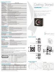
Physical Dimensions<br />
41.8<br />
37.0<br />
38.5<br />
48.5<br />
1.5<br />
1/4-20 UNC 6.0<br />
M3X0.5 - 6H<br />
120.0 120.0<br />
18.5<br />
6.0<br />
FRONT VIEW<br />
STATUS LED<br />
164.5<br />
6.3<br />
TOP VIEW<br />
277.0<br />
66.0<br />
BOTTOM VIEW<br />
200.0<br />
20.0<br />
94.5<br />
12.0<br />
RIGHT VIEW<br />
Specification<br />
Imaging Sensor<br />
Baseline<br />
Lens Focal Length<br />
A/D Converter<br />
Video Data Output<br />
Frame Rates<br />
Interfaces<br />
Camera Specifications<br />
Three Sony ICX445 1/3” progressive scan CCD’s<br />
1280x960 max pixels, 3.75μm square pixels<br />
12 cm and 24 cm<br />
2.5mm with 100° HFOV or 3.8mm with 70° HFOV or 6mm with<br />
50° HFOV<br />
Analog Devices 12-bit analog-to-digital converter<br />
8 and 16-bit digital data (see Supported Data Formats below)<br />
15, 7.5, 3.75, 1.875 FPS<br />
Voltage Requirements 8-30V<br />
Power Consumption Less than 4W<br />
Gain<br />
2x 9-pin IEEE-1394b for camera control and video data transmission<br />
4 general-purpose digital input/output (GPIO) pins.<br />
Automatic/<strong>Manual</strong>/One-Push Gain modes<br />
0dB to 24dB<br />
0dB to 24dB<br />
Automatic/<strong>Manual</strong>/One-Push Shutter modes<br />
Shutter<br />
0.01ms to 66.63ms @15 FPS 0.01ms to 66.63ms @15 FPS<br />
Extended Shutter modes<br />
0.01ms to 7900ms @ 15 FPS 0.01ms to 5200ms @ 15 FPS<br />
Trigger Modes DCAM v1.31 Trigger Modes 0, 1, 3, and 14<br />
Signal To Noise Ratio TBD<br />
Dimensions<br />
276 x 36 x 41.8mm<br />
Mass<br />
505 grams<br />
Camera Specification IIDC 1394-based Digital Camera Specifi cation v1.31<br />
Emissions Compliance Complies with CE rules and Part 15 Class A of FCC Rules<br />
Operating Temperature Commercial grade electronics rated from 0° to 45°C<br />
Storage Temperature -30° to 60°C<br />
BACK VIEW<br />
24.6<br />
11.4<br />
1394B CONNECTORS<br />
GPIO CONNECTOR<br />
M3 CASE SCREWS<br />
Spectral Response (QE)<br />
For full sensor datasheets, visit www.ptgrey.com/support/kb/index.asp?a=4&q=23<br />
Status LED<br />
LED Status<br />
Description<br />
Steady on<br />
Camera receiving power and initialized<br />
Steady on and very bright<br />
Camera acquiring and transmitting images<br />
Flashing bright, then brighter<br />
Camera registers being accessed<br />
Steady or slow fl ashing on and off Firmware updated, or possible camera problem (power cycle)<br />
Camera Features<br />
Image Acquisition<br />
Feature<br />
Description<br />
Automatic Synchronization Multiple cameras on the same 1394 bus automatically sync<br />
Fast Frame Rates<br />
Faster standard frame rates<br />
Multiple Trigger Modes Bulb-trigger mode, overlapped trigger/transfer<br />
Embedded Image Info Pixels contain frame-specifi c info (e.g. shutter, 1394 cycle time)<br />
Camera and Device Control<br />
Feature<br />
Description<br />
Frame Rate Control Fine-tune frame rates for video conversion (e.g. PAL @ 24 FPS)<br />
Strobe Output<br />
Increased drive strength, confi gurable strobe pattern output<br />
RS-232 Serial Port<br />
Provides serial communication via GPIO TTL digital logic levels<br />
Memory Channels<br />
Non-volatile storage of camera default power-up settings<br />
Temperature Sensor Reports the temperature near the imaging sensor<br />
Camera Upgrades<br />
Firmware upgradeable in fi eld via IEEE-1394 interface.<br />
Calibration and Mechanics<br />
Feature<br />
Description<br />
Lens System<br />
High quality microlenses protected by removeable glass system<br />
Accurate Pre-Calibration For lens distortions and camera misalignments<br />
Stereo Pair Alignment Left and right images aligned to within 0.05 1 pixel RMS error<br />
Calibration Retention Minimizes loss of calibration due to shock and vibration<br />
Multiple Baselines<br />
Choice of 12 cm or 24 cm baseline for stereo processing<br />
1<br />
Based on epipolar accuracy at a stereo resolution of 320x240; valid for 1024x768 and 640x480 model.<br />
Stereo Image Formats<br />
The <strong>Bumblebee</strong> <strong>XB3</strong> can be confi gured to output images from any set of two sensors, or from all three<br />
sensors, at the same time. This image data is formatted as pixel (byte) interleaved stereo images using<br />
Format_7. Pixel interleaved images use a raw 24bit-per-pixel format. For color cameras, each sensor<br />
represents an RGB color channel, where red is from the right camera, blue from the left and green from<br />
the middle.<br />
Future fi rmware versions may support line (row) interleaved images, where the rows from each of the<br />
cameras are interleaved to speed processing.<br />
Mode Pixel Format Max Size FPS Description<br />
3 RGB8 (24bpp) 1280x960 15<br />
Pixel interleaved stereo image<br />
(8 bits from each imaging sensor)<br />
Single Camera Image Formats<br />
Standard Modes<br />
Frames Per Second (one camera only 1 )<br />
1.875 3.75 7.5 15 30 60<br />
1280x960 Y16 (16bpp) • • •<br />
1280x960 Y8 (8bpp) • • • •<br />
1<br />
Use the PAN control to select the camera that is outputting images<br />
Camera Interface<br />
IEEE-1394 Connector and Cables<br />
The <strong>Bumblebee</strong> ® <strong>XB3</strong> has a standard 9-pin IEEE-1394b connector that is used for data transmission,<br />
camera control and powering the camera. The maximum 1394 cable length between any 1394 node<br />
(e.g. camera to PCI card, card to hub, etc.) is 4.5m, as specifi ed by the IEEE-1394 standard. Use standard,<br />
shielded twisted pair copper cables.<br />
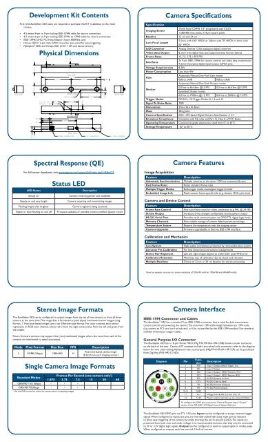
General Purpose I/O Connector<br />
The <strong>Bumblebee</strong> <strong>XB3</strong> has a 12-pin Hirose HR10 (Mfg P/N: HR10A-10R-12SB) female circular connector<br />
on the back of the case. Camera KIT contents include a pre-wired male connector; refer to the diagram<br />
below for wire color-coding. Additional male counterparts (Mfg P/N: HR10A-10P-12P) can be purchased<br />
from Digi-Key (P/N: HR112-ND).<br />
Diagram<br />
Pin<br />
Function<br />
Description<br />
1 IO0 Input / Output (default Trigger_Src)<br />
2 IO1 Input / Output<br />
3 IO2 Input / Output / RS232 Transmit (TX)<br />
4 IO3 Input / Output / RS232 Receive (RX)<br />
5 RTS RS-232 Request to Send<br />
6 CTS RS-232 Clear to Send<br />
7 TX RS-232 Transmit (Output)<br />
8 RX RS-232 Receive (Input)<br />
9, 10 GND<br />
11 VEXT Voltage limit: 8-30V; Current limit: 1A<br />
12 +3.3V Power external circuitry up to a total of 150mA<br />
To confi gure the GPIO pins, consult the “General Purpose Input / Output”<br />
section of the PGR IEEE-1394 Digital Camera Register Reference.<br />
The <strong>Bumblebee</strong> <strong>XB3</strong> GPIO pins are TTL 3.3V pins. Inputs can be confi gured to accept external trigger<br />
signals. When confi gured as inputs, the pins are internally pulled high using weak pull-up resistors<br />
to allow easy triggering of the camera by simply shorting the pin to ground (GND). The inputs are<br />
protected from both over and under voltage. It is recommended, however, that they only be connected<br />
to 5V or 3.3V digital logic signals. Outputs can be confi gured to send an output signal or strobe pulse.<br />
When confi gured as outputs, each line can sink 10mA of current.
1 Installation 2<br />
Installation<br />
1. Recommended System Configuration<br />
• Windows ® XP Service Pack 1<br />
• 512MB of RAM<br />
• Intel ® Pentium 4 2.0GHz or compatible processor<br />
• AGP video card with 128MB video memory<br />
• PCI slot for the IEEE-1394 OHCI card (PCI Express recommended)<br />
• Microsoft ® Visual C++ 6.0 (to compile and run example code)<br />
2. Electrostatic Precautions and Camera Care<br />
• To avoid static discharge that could damage a camera, users should:<br />
o Either handle bare handed or use non-chargeable gloves, clothes<br />
or material. Also use conductive shoes.<br />
o Install a conductive mat on the floor or working table to prevent<br />
the generation of static electricity.<br />
• When handling the camera unit, avoid touching the lenses. To clean the<br />
lenses, use a standard camera lens cleaning kit or a clean dry cotton<br />
cloth. Do not apply excessive force.<br />
• Extended exposure to bright sunlight, rain, dusty environments, etc. may<br />
cause problems with the electronics and the optics of the system.<br />
• Avoid excessive shaking, dropping or mishandling of the device.<br />
3. Install the IEEE-1394 PCI card<br />
• Place the IEEE-1394 PCI card in an open PCI slot.<br />
• Connect the 4-pin connector on the card to the PC power supply.<br />
• Turn the computer back on and log into Windows.<br />
• In most cases, the Windows IEEE-1394 drivers will be automatically<br />
installed for the card, with no user input required. However, in some cases<br />
the Found New Hardware Wizard will appear. Follow the prompts given by<br />
the Wizard to install the card.<br />
• Open Windows Device Manager by going to the Control Panel > System<br />
> Hardware tab > Device Manager. Ensure that the PCI card is properly<br />
installed as an IEEE 1394 Bus host controller.<br />
4. Install the FlyCapture ® and Triclops Software<br />
• Insert the software CD-ROM. If the Installation Wizard does not<br />
automatically run, browse to your CD-ROM directory and run setup.exe.<br />
• Follow the installation instructions to install the software.<br />
<br />
IMPORTANT NOTE for Windows XP Users<br />
A dialog will appear prompting you to install the PGR1394b-PRO driver. We<br />
strongly recommend that users do this in order to take full advantage of 1394b<br />
800Mb/s speeds. See this Knowledge Base article for further information:<br />
www.ptgrey.com/support/kb/index.asp?a=4&q=171<br />
3 4<br />
Installation<br />
Installation<br />
5. Connect the 1394 PCI Card and Cable to the Camera<br />
• Plug the 4.5 meter IEEE-1394 cable into the 1394 PCI card and the<br />
camera’s 1394 connector.<br />
NOTE: The camera relies on the 1394 cable to provide power. If using<br />
an interface card other than that provided, ensure that adequate power<br />
is provided.<br />
• If the Microsoft Windows “Found New Hardware Wizard” appears,<br />
proceed to Step 7. Otherwise, proceed to Step 8.<br />
6. Install the Camera Driver<br />
• Click “Install from a list or specifi c location” and click “Next”.<br />
• Select “Don’t search. I will choose the driver to install” and “Next”.<br />
• Click “Have Disk” and browse to C:\Program Files\Point Grey Research\PGR<br />
FlyCapture\driver, click “Open”, then “OK”.<br />
• Select the camera model and click “Next”. You will be prompted to<br />
continue installation - click “Continue Anyway” then “Finish” to complete<br />
installation.<br />
7. Confirm Successful Installation<br />
• Check the Device Manager to confi rm that installation was successful. Go<br />
to the Start menu, select Run and enter “devmgmt.msc”.<br />
8. Test Camera Capabilities<br />
• To test the camera’s image acquisition capabilities, run FlyCap. From the<br />
Start menu, select All Programs > Point Grey Research > PGR FlyCapture ><br />
FlyCap.exe.<br />
• To test stereo processing, run TriclopsDemo. From the Start menu, select<br />
All Programs > Point Grey Research > Triclops SDK > TriclopsDemo.exe.<br />
5 Troubleshooting<br />
Technical references can be found in the Programs > Point Grey Research ><br />
directory. Our on-line Knowledge Base (www.ptgrey.com/support/kb/) also<br />
addresses the following problems:<br />
• Article 21: Troublesome hardware confi gurations<br />
• Article 91: PGR camera not recognized by system and not listed in Device Manager<br />
• Article 93: My laptop’s IEEE-1394 port or PCMCIA card doesn’t supply power to my camera<br />
• Article 145: Image discontinuities or horizontal tearing of images when displayed on monitor<br />
• Article 171: Performance of 1394 devices may decrease after installing Windows XP SP2<br />
• Article 188: Image data acquired by my camera is corrupt and displayed images are broken<br />
• Article 189: Image capture freezes after a period of successful image capture.<br />
Contacting Point Grey Research<br />
Email:<br />
Email:<br />
For<br />
For<br />
all<br />
all<br />
general<br />
general<br />
questions<br />
questions<br />
about<br />
about<br />
Point<br />
Point<br />
Grey<br />
Grey<br />
Research<br />
Research<br />
please<br />
please<br />
contact<br />
contact<br />
us<br />
us<br />
at<br />
at<br />
info@ptgrey.com.<br />
info@ptgrey.com.<br />
For<br />
For<br />
technical<br />
technical<br />
support<br />
support<br />
(existing<br />
(existing<br />
customers<br />
customers<br />
only)<br />
only)<br />
contact<br />
contact<br />
us<br />
us<br />
at<br />
at<br />
www.ptgrey.com/support/contact/.<br />
www.ptgrey.com/support/contact/.<br />
Main<br />
Main<br />
Office:<br />
Office:<br />
Mailing<br />
Mailing<br />
Address:<br />
Address:<br />
Tel:<br />
Tel:<br />
+1<br />
+1<br />
(604)<br />
(604)<br />
730-9937<br />
730-9937<br />
Point<br />
Point<br />
Grey<br />
Grey<br />
Research,<br />
Research,<br />
Inc.<br />
Inc.<br />
Fax:<br />
Toll<br />
+1<br />
Free<br />
(604)<br />
(N.<br />
732-8231<br />
America only):<br />
8866<br />
12051<br />
Hudson<br />
Riverside<br />
Street<br />
Way<br />
Email:<br />
+1 (866)<br />
sales@ptgrey.com<br />
765-0827<br />
Vancouver<br />
Richmond<br />
B.C.<br />
B.C.<br />
Canada<br />
Canada Fax: +1 (604) 242-9938<br />
V6P<br />
V6W<br />
4N2<br />
1K7<br />
Email: sales@ptgrey.com<br />
<strong>Bumblebee</strong> ® <strong>XB3</strong><br />
IEEE-1394b Stereo Vision Digital Camera System<br />
Knowledge<br />
Knowledge<br />
Base:<br />
Base:<br />
Downloads:<br />
Downloads:<br />
Find<br />
Find<br />
answers<br />
answers<br />
to<br />
to<br />
commonly<br />
commonly<br />
asked<br />
asked<br />
questions<br />
questions<br />
in<br />
in<br />
our<br />
our<br />
knowledge<br />
knowledge<br />
base<br />
base<br />
at<br />
at<br />
www.ptgrey.com/support/kb/.<br />
www.ptgrey.com/support/kb/.<br />
Users<br />
Users<br />
can<br />
can<br />
download<br />
download<br />
the<br />
the<br />
latest<br />
latest<br />
manuals<br />
manuals<br />
and<br />
and<br />
software<br />
software<br />
from<br />
from<br />
www.ptgrey.com/support/downloads/.<br />
www.ptgrey.com/support/downloads/.<br />
<strong>Getting</strong> <strong>Started</strong><br />
<strong>Manual</strong><br />
Document Document revised revised November April 11, 6, 2007 2008<br />
Copyright Copyright © Point © Point Grey Grey Research Research Inc. Inc. 2006. 2006. All All rights rights reserved. reserved.<br />
PGR, PGR, the the Point Point Grey Grey Research, Research, Inc. Inc. logo, logo, <strong>Bumblebee</strong> <strong>Bumblebee</strong> and and FlyCapture FlyCapture are are trademarks trademarks of Point of Point Grey Grey Research, Research, Inc. Inc. in Canada in Canada and and other other countries. countries.