
Create successful ePaper yourself
Turn your PDF publications into a flip-book with our unique Google optimized e-Paper software.
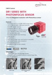
<strong>Blackfly</strong><br />
PoE Digital Camera<br />
Technical Reference<br />
Version 1.0<br />
Revised 12/13/2012<br />
Point Grey Research ® Inc.<br />
12051 Riverside Way • Richmond, BC • Canada • V6W 1K7 • T (604) 242-9937 • www.ptgrey.com<br />
Copyright © 2012 Point Grey Research Inc. All Rights Reserved.
FCC Compliance<br />
This device complies with Part 15 of the FCC rules. Operation is subject to the following two conditions:<br />
(1) This device may not cause harmful interference, and (2) this device must accept any interference<br />
received, including interference that may cause undesirable operation.<br />
Hardware Warranty<br />
Point Grey Research®, Inc. (Point Grey) warrants to the Original Purchaser that the Camera Module<br />
provided with this package is guaranteed to be free from material and manufacturing defects for a<br />
period of 3 years. Should a unit fail during this period, Point Grey will, at its option, repair or replace the<br />
damaged unit. Repaired or replaced units will be covered for the remainder of the original equipment<br />
warranty period. This warranty does not apply to units that, after being examined by Point Grey, have<br />
been found to have failed due to customer abuse, mishandling, alteration, improper installation or<br />
negligence. If the original camera module is housed within a case, removing the case for any purpose<br />
other than to remove the protective glass or filter over the sensor voids this warranty. This warranty does<br />
not apply to damage to any part of the optical path resulting from removal or replacement of the<br />
protective glass or filter over the camera, such as scratched glass or sensor damage.<br />
Point Grey Research, Inc. expressly disclaims and excludes all other warranties, express, implied and<br />
statutory, including, but without limitation, warranty of merchantability and fitness for a particular<br />
application or purpose. In no event shall Point Grey Research, Inc. be liable to the Original Purchaser or<br />
any third party for direct, indirect, incidental, consequential, special or accidental damages, including<br />
without limitation damages for business interruption, loss of profits, revenue, data or bodily injury or<br />
death.<br />
WEEE<br />
The symbol indicates that this product may not be treated as household waste. Please ensure<br />
this product is properly disposed as inappropriate waste handling of this product may cause<br />
potential hazards to the environment and human health. For more detailed information<br />
about recycling of this product, please contact Point Grey Research.<br />
Trademarks<br />
Point Grey Research, PGR, the Point Grey Research, Inc. logo, <strong>Blackfly</strong>, Bumblebee, Chameleon, Digiclops,<br />
Dragonfly, Dragonfly Express, Firefly, Flea, FlyCapture, Gazelle, Grasshopper, Ladybug, Triclops and Zebra<br />
are trademarks or registered trademarks of Point Grey Research, Inc. in Canada and other countries.
Point Grey <strong>Blackfly</strong> Technical Reference<br />
Table of Contents<br />
Contacting Point Grey Research<br />
i<br />
1 <strong>Blackfly</strong> Specifications 1<br />
1.1 <strong>Blackfly</strong> Specifications 1<br />
1.2 Handling Precautions and Camera Care 3<br />
1.2.1 Case Temperature and Heat Dissipation 3<br />
2 <strong>Blackfly</strong> Installation 5<br />
2.1 Before You Install 5<br />
2.1.1 Will your system configuration support the camera? 5<br />
2.1.2 Do you have all the parts you need? 5<br />
2.1.3 Do you have a downloads account? 5<br />
2.2 Installing Your Interface Card and Software 6<br />
2.3 Installing Your Camera 7<br />
2.4 Configuring Camera Setup 8<br />
2.4.1 Configuring Camera Drivers 8<br />
2.4.2 Configuring the IP Address 9<br />
2.4.3 Allocating Bandwidth 10<br />
2.4.3.1 Packet Size 10<br />
2.4.3.2 Packet Delay 11<br />
2.4.3.3 Determining Bandwidth Requirements 11<br />
2.4.4 Configuring Other Network Settings 12<br />
2.4.4.1 Stream Channel Destination Address 12<br />
2.4.4.2 Heartbeat 12<br />
3 Tools to Control the <strong>Blackfly</strong> 14<br />
3.1 Using FlyCapture 14<br />
3.2 Using GenICam Applications 14<br />
3.3 Using GigE Vision Bootstrap Registers 15<br />
3.4 Using Control and Status Registers 15<br />
3.4.1 Modes 15<br />
3.4.2 Values 15<br />
4 <strong>Blackfly</strong> Physical Interface 16<br />
4.1 <strong>Blackfly</strong> Physical Description 16<br />
4.2 <strong>Blackfly</strong> Dimensions 17<br />
4.3 Tripod Adapter Dimensions 18<br />
4.4 Mounting with the Case or Mounting Bracket 18<br />
4.5 Lens Mounting 19<br />
Revised 12/13/2012<br />
Copyright ©2012 Point Grey Research Inc.
Point Grey <strong>Blackfly</strong> Technical Reference<br />
4.5.1 Back Flange Distance 19<br />
4.6 Dust Protection 19<br />
4.7 Infrared Cut-Off Filters 20<br />
4.8 Camera Interface and Connectors 21<br />
4.8.1 Ethernet Connector 21<br />
4.8.2 Interface Cables 21<br />
4.8.3 Interface Card 21<br />
4.8.4 General Purpose Input/Output (GPIO) 21<br />
5 General <strong>Blackfly</strong> Operation 23<br />
5.1 Powering the Camera 23<br />
5.2 User Sets (Memory Channels) 23<br />
5.2.1 GenICam User Set Control 24<br />
5.3 On-Camera Frame Buffer 24<br />
5.4 Non-Volatile Flash Memory 25<br />
5.5 Camera Firmware 25<br />
5.5.1 Determining Firmware Version 26<br />
5.5.2 Upgrading Camera Firmware 26<br />
6 Input/Output Control 27<br />
6.1 General Purpose Input/Output (GPIO) 27<br />
6.2 GPIO Modes 27<br />
6.2.1 GPIO Mode 0: Input 27<br />
6.2.2 GPIO Mode 1: Output 27<br />
6.2.3 GPIO Mode 2: Asynchronous (External) Trigger 27<br />
6.2.4 GPIO Mode 3: Strobe 28<br />
6.2.5 GPIO Mode 4: Pulse Width Modulation (PWM) 28<br />
6.3 GenICam Digital Input/Output Control 28<br />
6.4 Programmable Strobe Output 29<br />
6.5 Pulse Width Modulation (PWM) 29<br />
6.6 GPIO Electrical Characteristics 31<br />
6.6.1 Output Timing Characteristics 31<br />
6.6.2 Input Timing Characteristics 33<br />
7 Image Acquisition Control 34<br />
7.1 Asynchronous Triggering 34<br />
7.1.1 GenICam Acquisition Control 34<br />
7.1.2 Trigger Mode 0 (“Standard External Trigger Mode”) 36<br />
7.1.3 Trigger Mode 15 (“Multi-Shot Trigger Mode”) 37<br />
7.2 External Trigger Timing 38<br />
7.3 Maximum Frame Rate in External Trigger Mode 38<br />
Revised 12/13/2012<br />
Copyright ©2012 Point Grey Research Inc.
Point Grey <strong>Blackfly</strong> Technical Reference<br />
7.4 Camera Behavior Between Triggers 39<br />
7.5 Changing Video Modes While Triggering 39<br />
7.6 Asynchronous Software Triggering 39<br />
8 <strong>Blackfly</strong> Attributes 41<br />
8.1 Pixel Formats 41<br />
8.1.1 Raw 41<br />
8.1.2 Mono 41<br />
8.1.3 RGB 41<br />
8.1.4 YUV 41<br />
8.2 Video Modes Overview 42<br />
8.2.1 Video Mode Descriptions 43<br />
8.3 GenICam Image Format Control 44<br />
8.4 Frame Rates 45<br />
8.4.1 Calculating Maximum Possible Frame Rate 45<br />
8.5 Shutter Type 46<br />
8.5.1 Global Shutter 46<br />
8.5.2 Rolling Shutter 46<br />
8.6 Overview of Imaging Parameters 48<br />
8.7 GenICam Analog Control 49<br />
8.8 Brightness 51<br />
8.9 Exposure 51<br />
8.9.1 Extended ExposureTimes 52<br />
8.10 Gain 52<br />
8.11 Auto Exposure 53<br />
8.12 Sharpness 54<br />
8.13 Gamma and Lookup Table 54<br />
8.14 Image Flip/Mirror 55<br />
8.15 Embedded Image Information 56<br />
8.16 Color Model Attributes 58<br />
8.16.1 White Balance 58<br />
8.16.2 Bayer Color Processing 59<br />
8.16.2.1 Accessing Raw Bayer Data 60<br />
8.16.3 Hue 60<br />
8.16.4 Saturation 60<br />
9 Troubleshooting 62<br />
9.1 Support 62<br />
9.2 Status Indicator LED 63<br />
9.3 Test Pattern 63<br />
Revised 12/13/2012<br />
Copyright ©2012 Point Grey Research Inc.
Point Grey <strong>Blackfly</strong> Technical Reference<br />
9.3.1 Image Format Control—Test Image 63<br />
9.4 Blemish Pixel Artifacts 64<br />
9.4.1 Pixel Defect Correction 64<br />
9.5 Rolling Shutter Artifacts 64<br />
Appendix A: GenICam Features 65<br />
A.1 Device Control 65<br />
A.2 Analog Control 65<br />
A.3 Image Format Control 66<br />
A.4 Acquisition Control 68<br />
A.5 Digital Input Output Control 69<br />
A.6 Transport Layer Control 69<br />
A.7 User Set Control 73<br />
Appendix B: GigE Vision Bootstrap Registers 74<br />
Appendix C: FlyCapture API Code Examples 76<br />
C.1 Example: Setting a GPIO Pin to Strobe Using the FlyCapture API 76<br />
C.2 Example: Setting a Standard Video Mode, Format and Frame Rate Using the FlyCapture API 76<br />
C.3 Example: Asynchronous Hardware Triggering Using the FlyCapture API 76<br />
C.4 Example: Setting Brightness Using the FlyCapture API 77<br />
C.5 Example: Setting Shutter Using the FlyCapture API 77<br />
C.6 Example: Setting Gain Using the FlyCapture API 78<br />
C.7 Example: Setting Auto Exposure Using the FlyCapture API 78<br />
C.8 Example: Setting Saturation Using the FlyCapture API 79<br />
C.9 Example: Setting Hue Using the FlyCapture API 79<br />
C.10 Example: Setting Sharpness Using the FlyCapture API 80<br />
C.11 Example: Setting Gamma Using the FlyCapture API 80<br />
C.12 Example: Setting White Balance Using the FlyCapture API 81<br />
C.13 Example: Accessing Raw Bayer Data using FlyCapture 81<br />
Appendix C: Control and Status Registers 82<br />
C.1 IMAGE_RETRANSMIT: 634h 82<br />
C.2 DATA_FLASH_CTRL: 1240h 83<br />
C.3 DATA_FLASH_DATA: 1244h 83<br />
C.4 GPIO_CTRL_PIN: 1110h-1140h 84<br />
C.5 GPIO_XTRA_PIN: 1114h-1144h 85<br />
C.6 TRIGGER_MODE: 830h 85<br />
C.7 AE_ROI: 1A70 – 1A74h 86<br />
C.8 LUT: 80000h – 80048h (IIDC 1.32) 87<br />
C.9 FRAME_INFO: 12F8h 89<br />
C.10 PIXEL_DEFECT_CTRL: 1A60h 90<br />
Revised 12/13/2012<br />
Copyright ©2012 Point Grey Research Inc.
Point Grey <strong>Blackfly</strong> Technical Reference<br />
Revision History 91<br />
Revised 12/13/2012<br />
Copyright ©2012 Point Grey Research Inc.
Point Grey <strong>Blackfly</strong> Technical Reference<br />
List of Tables<br />
Table 1.1: Temperature Sensor Specifications 3<br />
Table 3.1: CSR Mode Control Descriptions 15<br />
Table 6.1: GPIO pin assignments (as shown looking at rear of camera) 27<br />
Table 6.2: Operating Range 31<br />
Table 6.3: Absolute Maximum Ratings 31<br />
Table 6.4: Opto-isolated Output Performance (measured at Vcc = 5 V, Rext = 1 kΩ) 32<br />
Table 6.5: Sample Opto-isolated Output Voltage/Current Measurements 32<br />
Revised 12/13/2012<br />
Copyright ©2012 Point Grey Research Inc.
Point Grey <strong>Blackfly</strong> Technical Reference<br />
List of Figures<br />
Figure 2.1: Point Grey GigE Configurator 10<br />
Figure 4.1: <strong>Blackfly</strong> Dimensional Diagram 17<br />
Figure 4.2: Tripod Adapter Dimensional Diagram 18<br />
Figure 6.1: Output Timing Characteristics 31<br />
Figure 6.2: Input Timing Characteristics 33<br />
Figure 7.1: Trigger Mode 0 (“Standard External Trigger Mode”) 36<br />
Figure 7.2: Trigger Mode 15 (“Multi-Shot Trigger Mode”) 37<br />
Figure 7.3: External trigger timing characteristics 38<br />
Figure 7.4: Relationship Between External Triggering and Video Mode Change Request 39<br />
Figure 7.5: Software trigger timing 40<br />
Figure 8.1: Aggregation and Decimation of Pixels 42<br />
Figure 8.2: Example Bayer Tile Pattern 59<br />
Figure 9.1: Test Pattern Sample Image 63<br />
Revised 12/13/2012<br />
Copyright ©2012 Point Grey Research Inc.
Point Grey <strong>Blackfly</strong> Technical Reference<br />
Contacting Point Grey Research<br />
Contacting Point Grey Research<br />
For any questions, concerns or comments please contact us via the following methods:<br />
Email<br />
General questions about Point Grey Research<br />
Technical support (existing customers only)<br />
Knowledge Base Find answers to commonly asked questions in our Knowledge Base<br />
Downloads Download the latest documents and software<br />
Main Office<br />
USA<br />
Europe and Israel<br />
Point Grey Research, Inc.<br />
12051 Riverside Way<br />
Richmond, BC, Canada V6W 1K7<br />
Point Grey Research GmbH Schwieberdinger<br />
Strasse 60<br />
71636 Ludwigsburg<br />
Germany<br />
Tel: +1 (604) 242-9937<br />
Toll Free +1 (866) 765-0827<br />
(North America only)<br />
Fax: +1 (604) 242-9938<br />
Email: sales@ptgrey.com<br />
Tel: +1 (866) 765-0827<br />
Email:na-sales@ptgrey.com<br />
Tel: +49 7141 488817-0<br />
Fax: +49 7141 488817-99<br />
Email:eu-sales@ptgrey.com<br />
Distributors<br />
Singapore, Malaysia &<br />
Thailand<br />
Japan ViewPLUS Inc<br />
Korea Cylod Co. Ltd.<br />
China LUSTER LightVision Tech. Co., Ltd.<br />
Voltrium Systems Pte Ltd.<br />
www.voltrium.com.sg<br />
Taiwan Apo Star Co., Ltd.<br />
United Kingdom ClearView Imaging Ltd.<br />
www.viewplus.co.jp<br />
www.cylod.com<br />
www.lusterlighttech.com<br />
www.apostar.com.tw<br />
www.clearviewimaging.co.uk<br />
Revised 12/13/2012<br />
Copyright ©2012 Point Grey Research Inc.<br />
i
Point Grey <strong>Blackfly</strong> Technical Reference<br />
Contacting Point Grey Research<br />
About This Manual<br />
This manual provides the user with a detailed specification of the <strong>Blackfly</strong> camera system. The user should be aware<br />
that the camera system is complex and dynamic – if any errors or omissions are found during experimentation, please<br />
contact us. (See Contacting Point Grey Research on previous page.)<br />
This document is subject to change without notice.<br />
All model- specific information presented in this manual reflects functionality available in the<br />
model's firmware version.<br />
For more information see Camera Firmware on page 25.<br />
Where to Find Information<br />
Chapter<br />
<strong>Blackfly</strong> Specifications<br />
<strong>Blackfly</strong> Installation<br />
Tools to Control the <strong>Blackfly</strong><br />
<strong>Blackfly</strong> Physical Interface<br />
General <strong>Blackfly</strong> Operation<br />
Input/Output Control<br />
Image Acquisition Control<br />
<strong>Blackfly</strong> Attributes<br />
Troubleshooting<br />
Appendix: GenICam Features<br />
Appendix: GigE Vision Bootstrap<br />
Registers<br />
Appendix: FlyCapture API Code<br />
Examples<br />
What You Will Find<br />
General camera specifications and specific model specifications, and camera properties.<br />
Instructions for installing the <strong>Blackfly</strong>, as well as introduction to <strong>Blackfly</strong> configuration.<br />
Information on the tools available for controlling the <strong>Blackfly</strong>.<br />
Information on the mechanical properties of the <strong>Blackfly</strong>.<br />
Information on powering the <strong>Blackfly</strong>, monitoring status, user configuration sets, memory<br />
controls, and firmware.<br />
Information on input/output modes and controls.<br />
Information on asynchronous triggering and supported trigger modes.<br />
Information on supported imaging parameters and their controls.<br />
Information on how to get support, diagnostics for the <strong>Blackfly</strong>, and common sensor<br />
artifacts.<br />
Information on GenICam Feature controls.<br />
Information on GigE Vision Bootstrap Registers.<br />
Examples of FlyCapture API code.<br />
Document Conventions<br />
This manual uses the following to provide you with additional information:<br />
A note that contains information that is distinct from the main body of text. For example,<br />
drawing attention to a difference between models; or a reminder of a limitation.<br />
Revised 12/13/2012<br />
Copyright ©2012 Point Grey Research Inc.<br />
ii
Point Grey <strong>Blackfly</strong> Technical Reference<br />
Contacting Point Grey Research<br />
A note that contains a warning to proceed with caution and care, or to indicate that the<br />
information is meant for an advanced user. For example, indicating that an action may void<br />
the camera's warranty.<br />
If further information can be found in our Knowledge Base, a list of articles is provided.<br />
Related Knowledge Base Articles<br />
Title<br />
Article<br />
Title of the Article Link to the article on the Point Grey website<br />
If there are further resources available, a link is provided either to an external website, or to the FlyCapture SDK.<br />
Related Resources<br />
Title<br />
Title of the resource<br />
Link to the resource<br />
Link<br />
Revised 12/13/2012<br />
Copyright ©2012 Point Grey Research Inc.<br />
iii
Point Grey <strong>Blackfly</strong> Technical Reference<br />
1 <strong>Blackfly</strong> Specifications<br />
1 <strong>Blackfly</strong> Specifications<br />
1.1 <strong>Blackfly</strong> Specifications<br />
MODEL VERSION MP IMAGING SENSOR<br />
BFLY-PGE-13E4C-CS<br />
BFLY-PGE-13E4M-CS<br />
Color<br />
Mono<br />
1.3 MP<br />
• e2v EV76C560 CMOS, 1/1.8", 5.3 µm<br />
• Global shutter<br />
• 1280 x 1024 at 60 FPS<br />
A/D Converter<br />
Video Data Output<br />
Image Data Formats<br />
Partial Image Modes<br />
Image Processing<br />
Shutter<br />
Gain<br />
Gamma<br />
White Balance<br />
Color Processing<br />
Digital Interface<br />
Transfer Rates<br />
GPIO<br />
External Trigger Modes<br />
Synchronization<br />
Image Buffer<br />
Memory Channels<br />
Flash Memory<br />
Dimensions<br />
Mass<br />
Power Consumption<br />
10-bit (BFLY-PGE-13E4)/12-bit<br />
8, 12, 16 and 24-bit digital data<br />
All <strong>Blackfly</strong> Models<br />
Mono8, Mono12, Mono16, Raw8, Raw12, Raw16 (all models); RGB, YUV411, YUV422,<br />
YUV 444 (color models)<br />
Pixel binning, decimation, and region of interest (ROI) modes<br />
Gamma, lookup table, hue, saturation, and sharpness<br />
Global shutter; Automatic*/manual/one-push* (*free running only BFLY-PGE-13E4)<br />
0.015 ms to 1 second (extended shutter mode)<br />
Automatic*/manual/one-push* (*free running only for BFLY-PGE-13E4)<br />
0 dB to 18 dB<br />
0.50 to 3.99, programmable lookup table<br />
Automatic*/manual/one-push* (*free running only BFLY-PGE-13E4)<br />
On-camera in YUV or RGB format, or on-PC in Raw format<br />
Gigabit Ethernet interface with screw locks for camera control and data; Power over<br />
Ethernet<br />
10/100/1000 Mbit/s<br />
6-pin Hirose HR10A-7R-6PB GPIO connector for trigger, strobe, and power<br />
Standard and multi shot<br />
Via external trigger or software trigger<br />
16 MB frame buffer<br />
2 user configuration sets for custom camera settings<br />
512 KB non-volatile memory<br />
29 mm x 29 mm x 30 mm excluding lens holder, without optics (metal case)<br />
36 grams (without optics)<br />
Standard voltage via Power over Ethernet (PoE) or 5 - 16 V via GPIO interface,<br />
maximum 2.5 W (2 W BFLY-PGE-13E4)<br />
Revised 12/13/2012<br />
Copyright ©2012 Point Grey Research Inc.<br />
1
Point Grey <strong>Blackfly</strong> Technical Reference<br />
1 <strong>Blackfly</strong> Specifications<br />
All <strong>Blackfly</strong> Models<br />
Machine Vision Standard GigE Vision v1.2<br />
Camera Control<br />
Via FlyCapture SDK or GigE Vision third party software<br />
Camera Updates<br />
In-field firmware updates<br />
Lens Mount<br />
CS-mount (5 mm C-mount adapter not included)<br />
Temperature Operating: 0° to 45°C; Storage: -30° to 60°C<br />
Compliance<br />
CE, FCC, RoHS<br />
Operating System<br />
Windows, Linux (32- and 64-bit)<br />
Warranty<br />
3 years<br />
Revised 12/13/2012<br />
Copyright ©2012 Point Grey Research Inc.<br />
2
Point Grey <strong>Blackfly</strong> Technical Reference<br />
1 <strong>Blackfly</strong> Specifications<br />
1.2 Handling Precautions and Camera Care<br />
Do not open the camera housing. Doing so voids the Hardware<br />
Warranty described at the beginning of this manual.<br />
Your Point Grey digital camera is a precisely manufactured device and should be handled with care. Here are some<br />
tips on how to care for the device.<br />
• Avoid electrostatic charging.<br />
• When handling the camera unit, avoid touching the lenses. Fingerprints will affect the quality of the image<br />
produced by the device.<br />
• To clean the lenses, use a standard camera lens cleaning kit or a clean dry cotton cloth. Do not apply excessive<br />
force.<br />
• Extended exposure to bright sunlight, rain, dusty environments, etc. may cause problems with the electronics<br />
and the optics of the system.<br />
• Avoid excessive shaking, dropping or any kind of mishandling of the device.<br />
Related Knowledge Base Articles<br />
Title<br />
Article<br />
Solving problems with static electricity Knowledge Base Article 42<br />
Cleaning the imaging surface of your camera Knowledge Base Article 66<br />
1.2.1 Case Temperature and Heat Dissipation<br />
You must provide sufficient heat dissipation to control the internal operating temperature of the camera.<br />
The camera is equipped with an on-board temperature sensor. It allows you to obtain the temperature of the camera<br />
board-level components. The sensor measures the ambient temperature within the case.<br />
Table 1.1: Temperature Sensor Specifications<br />
Accuracy<br />
Range<br />
Resolution<br />
±2.0°C from -25°C to +100°C<br />
±3.0°C from -55°C to +120°C<br />
-55°C to +125°C<br />
0.125°C<br />
As a result of packing the camera electronics into a small space, the outer case of the camera can<br />
become very warm to the touch when running in some high data rate video modes. This is<br />
expected behavior and will not damage the camera electronics.<br />
Revised 12/13/2012<br />
Copyright ©2012 Point Grey Research Inc.<br />
3
Point Grey <strong>Blackfly</strong> Technical Reference<br />
1 <strong>Blackfly</strong> Specifications<br />
To reduce heat, use a cooling fan to set up a positive air flow around the camera, taking into consideration the<br />
following precautions:<br />
• Mount the camera on a heat sink, such as a camera mounting bracket, made out of a heat-conductive material<br />
like aluminum.<br />
• Make sure the flow of heat from the camera case to the bracket is not blocked by a non-conductive material<br />
like plastic.<br />
• Make sure the camera has enough open space around it to facilitate the free flow of air.<br />
Access this feature using:<br />
Device Control<br />
GenICam<br />
Revised 12/13/2012<br />
Copyright ©2012 Point Grey Research Inc.<br />
4
Point Grey <strong>Blackfly</strong> Technical Reference<br />
2 <strong>Blackfly</strong> Installation<br />
2 <strong>Blackfly</strong> Installation<br />
2.1 Before You Install<br />
2.1.1 Will your system configuration support the camera?<br />
Recommended System Configuration<br />
Operating<br />
System<br />
Windows, Linux<br />
(32- and 64-bit)<br />
CPU RAM Video Ports Software<br />
Intel Core 2 Duo,<br />
or equivalent<br />
2 GB<br />
128<br />
MB<br />
Ethernet<br />
Microsoft Visual Studio 2005 SP1 and SP1 Update for<br />
Vista (to compile and run example code)<br />
2.1.2 Do you have all the parts you need?<br />
To install your camera you will need the following components:<br />
• Ethernet cable (on page 21)<br />
• 6-pin GPIO connector (on page 21)<br />
• Powered Ethernet switch or Ethernet power injector (if using PoE)<br />
• CS-mount (or C-mount with adaptor) Lens (on page 19)<br />
• Tripod adapter (optional) (page 18)<br />
• Interface card (on page 21)<br />
Point Grey sells a number of the additional parts required for installation. To purchase, visit the Point Grey Webstore<br />
or the Products Accessories page.<br />
2.1.3 Do you have a downloads account?<br />
The Point Grey downloads page has many resources to help you operate your camera effectively, including:<br />
• Software, including Drivers (required for installation)<br />
• Firmware updates and release notes<br />
• Dimensional drawings and CAD models<br />
• Documentation<br />
To access the downloads resources you must have a downloads account.<br />
1. Go to the Point Grey downloads page.<br />
2. Under Register (New Users), complete the form, then click Submit.<br />
After you submit your registration, you will receive an email with instructions on how to activate your account.<br />
Revised 12/13/2012<br />
Copyright ©2012 Point Grey Research Inc.<br />
5
Point Grey <strong>Blackfly</strong> Technical Reference<br />
2 <strong>Blackfly</strong> Installation<br />
2.2 Installing Your Interface Card and Software<br />
1. Install your Interface Card<br />
Ensure the card is installed per the manufacturer's instructions.<br />
Alternatively, use your PC's built-in host controller, if equipped.<br />
If using a PoE enabled adapter to power the camera, connect the internal IDE or<br />
SATA power connector on the card to the computer power supply.<br />
Open the Windows Device Manager. Ensure the card is properly installed under Network Adaptors. An exclamation<br />
point (!) next to the card indicates the driver has not yet been installed.<br />
2. Install the FlyCapture® Software<br />
For existing users who already have FlyCapture installed, we recommend ensuring you have the<br />
latest version for optimal performance of your camera. If you do not need to install FlyCapture,<br />
use the DriverControlGUI to install and enable drivers for your card.<br />
a. Login to the Point Grey downloads page.<br />
b. Select your Camera and Operating System from the drop-down lists and click the Search button.<br />
c. Click on the Software search results to expand the list.<br />
d. Under FlyCapture v2x, click the appropriate link to begin the download and installation.<br />
After the download is complete, the FlyCapture setup wizard begins. If the wizard does not start automatically, doubleclick<br />
the .exe file to open it. Follow the steps in each setup dialog.<br />
3. Enable the Drivers for the card<br />
During the FlyCapture installation, you are prompted to select your interface driver.<br />
In the Interface Driver Selection dialog, select the I will use GigE cameras.<br />
This selection ensures the Point Grey Image Filter driver is installed and enabled. The Image Filter Driver<br />
operates as a network service between GigE Vision cameras and the Microsoft built-in UDP stack to filter out<br />
GigE Vision stream protocol (GVSP) packets. Use of the filter driver is recommended, as it can reduce CPU<br />
load and improve image streaming performance.<br />
Alternatively, Point Grey GigE Vision cameras can communicate directly with the Microsoft UDP stack.<br />
GigE Vision cameras on Linux systems use native Ubuntu drivers.<br />
To uninstall or reconfigure the driver at any time after setup is complete, use the DriverControlGUI (page 8).<br />
Revised 12/13/2012<br />
Copyright ©2012 Point Grey Research Inc.<br />
6
Point Grey <strong>Blackfly</strong> Technical Reference<br />
2 <strong>Blackfly</strong> Installation<br />
4. Configure IP Settings<br />
After installation is complete, the Point Grey GigE Configurator opens. This tool allows you to configure the IP settings<br />
of the camera and network card.<br />
If the GigE Configurator does not open automatically, open the tool from Start Menu>FlyCapture<br />
SDK>Utilities>GigE Configurator. If prompted to enable GigE enumeration, select Yes.<br />
a. In the left pane, select the Local Area Connection corresponding to the network interface card (NIC) to which<br />
the camera is connected.<br />
b. In the right pane, review maximum transmission unit (MTU). If not 9000, enable jumbo frames on the NIC by<br />
clicking Open Network Connections. (While most NICs support 9000-byte jumbo frames, this feature is often<br />
disabled by default.)<br />
2.3 Installing Your Camera<br />
1. Install the Tripod Mounting Bracket (optional)<br />
The ASA and ISO-compliant tripod mounting bracket attaches to the camera using the included<br />
metal screws.<br />
Cameras with metal cases should use metal screws; cameras with plastic cases should use plastic<br />
screws. Using improper screws may cause damage to the camera.<br />
2. Attach a Lens<br />
Unscrew the dust cap from the CS-mount lens holder to install a lens. Note: the camera can be used with a removable<br />
5 mm C- mount adapter.<br />
3. Connect the interface Card and Cable to the Camera<br />
Plug the interface cable into the host controller card and the camera. The cable jack<br />
screws can be used for a secure connection.<br />
If using PoE, connect a powered Ethernet switch or Ethernet power injector in between the card<br />
and the camera.<br />
4. Plug in the GPIO connector (optional)<br />
GPIO can be used for power, trigger, pulse width modulation, and strobe.<br />
Revised 12/13/2012<br />
Copyright ©2012 Point Grey Research Inc.<br />
7
Point Grey <strong>Blackfly</strong> Technical Reference<br />
2 <strong>Blackfly</strong> Installation<br />
5. Configure IP Settings<br />
In the GigE Configurator:<br />
a. In the left pane, select your GigE Vision camera. (Note: there may be a delay of several seconds before the<br />
camera is detected by the GigE Configurator on startup.)<br />
• Under "Current IP Configuration," review the IP address. By default, a dynamic IP address is assigned to<br />
the camera according to the DHCP protocol. If DHCP addressing fails, a link-local address is assigned. If<br />
necessary, change the IP address of the camera to be on the same subnet as the NIC. If the subnets do<br />
not match, the camera is marked "BAD" on the left pane.<br />
• Under "Packet Size Discover," click Discover Maximum Packet Size and note the value.<br />
b. Close the GigE Configurator.<br />
6. Confirm Successful Installation and Configure Packet Size<br />
a. Run the FlyCap program: Start-> FlyCapture SDK-> FlyCap<br />
b. In the camera selection dialog, select the GigE camera that was installed and click Configure Selected.<br />
c. In the Camera Control dialog, click Custom Video Modes. By default, Packet Size is set to 1400 bytes. We<br />
recommend increasing this value to the size noted in the GigE Configurator, as maximizing packet size reduces<br />
processing overhead.<br />
The FlyCap program can be used to test the camera's image acquisition capabilities through the Ethernet connection.<br />
Changes to your camera's installation configuration can be made using utilities available in the FlyCapture SDK (see<br />
Configuring Camera Setup below).<br />
2.4 Configuring Camera Setup<br />
After successful installation of your camera and interface card, you can make changes to the setup. Use the tools<br />
described below to change the IP Address or the driver for your interface card.<br />
For information on updating your camera's firmware post installation, see Camera Firmware on page 25.<br />
2.4.1 Configuring Camera Drivers<br />
Point Grey provides the Image Filter Driver for use with GigE Vision cameras. This driver operates as a network service<br />
between the camera and the Microsoft built-in UDP stack to filter out GigE vision stream protocol (GVSP) packets. The<br />
filter driver is installed and enabled by default as part of the FlyCapture SDK installation process. Use of the filter driver<br />
is recommended, as it can reduce CPU load and improve image streaming performance.<br />
Alternatively, Point Grey GigE Vision cameras can operate without the filter driver by communicating directly with the<br />
Microsoft UDP stack.<br />
GigE Vision cameras on Linux systems use native Ubuntu drivers.<br />
For more information about the image filter driver, see the FlyCapture SDK Help.<br />
Revised 12/13/2012<br />
Copyright ©2012 Point Grey Research Inc.<br />
8
Point Grey <strong>Blackfly</strong> Technical Reference<br />
2 <strong>Blackfly</strong> Installation<br />
To manage and update drivers use the DriverControlGUI utility provided in the SDK. To open the DriverControlGUI:<br />
Start Menu-->All Programs-->FlyCapture SDK-->Utilities-->DriverControlGUI<br />
Select the interface from the tabs in the top left. Then select your interface card to see the current setup.<br />
For more information about using the DriverControlGUI, see the online help provided in the tool.<br />
2.4.2 Configuring the IP Address<br />
When a new camera is first powered and initialized, a dynamic IP address is assigned to the camera according to the<br />
DHCP protocol. If DHCP addressing fails, a link-local address is assigned. You can re-configure the IP address for using<br />
the GigE Vision bootstrap registers (page 74) or the GenICam features (page 65).<br />
Alternatively, the Point Grey GigE Configurator is a tool included with the camera software and drivers package that<br />
allows you to set the internet protocol (IP) configuration for any GigE interface cards or Point Grey GigE Vision<br />
cameras connected to your system. Using the GigE Configurator, you can:<br />
• Set the IP address for the current connection.<br />
• Program a persistent IP address for the camera.<br />
• Configure the default IP addressing behavior of the camera on startup using a persistent IP, DHCP or LLA.<br />
• Enable Jumbo Frames on the GigE NIC.<br />
Both your camera and host adapter must have an IP address on the same subnet. This can be assigned in three ways:<br />
• Persistent—Both the adapter and the camera have a fixed IP address that will not change. Generally the<br />
address is within a closed network range of 192.168.X.X. The adapter and the camera must be on the same<br />
subnet.<br />
• Dynamic (DHCP)—Both the camera and the adapter are set to automatically obtain an IP address. This means<br />
that the IP address will dynamically change (within a range) every time the camera or computer is restarted. It<br />
may take up to one minute for the IP address to resolve and the camera to enumerate.<br />
• Default (LLA)—Both the camera and the adapter use a default IP address from the link-local address block<br />
169.254.x.x.<br />
The camera assigns its current IP address in the following sequence:<br />
1. Persistent—Uses the defined IP address. If not available, then;<br />
2. DHCP—Attempts to find a dynamic IP address. If not available, then;<br />
3. LLA—Uses the default IP address.<br />
The GigE Configurator can automatically force an IP address refresh. This detects the IP address of the Network<br />
Interface card and automatically sets the camera’s IP address relative to the card.<br />
The FlyCap program can be used to test your camera settings and verify operation. From the camera selection<br />
window, you can also automatically force an IP address refresh.<br />
To open the Point Grey GigE Configurator:<br />
Start Menu > All Programs > FlyCapture SDK > Utilities > GigEConfigurator<br />
Revised 12/13/2012<br />
Copyright ©2012 Point Grey Research Inc.<br />
9
Point Grey <strong>Blackfly</strong> Technical Reference<br />
2 <strong>Blackfly</strong> Installation<br />
Figure 2.1: Point Grey GigE Configurator<br />
For more information, refer to the online Help file included with the tool.<br />
2.4.3 Allocating Bandwidth<br />
The User Datagram Protocol (UDP) used by the GigE Vision standard provides no guaranteed transmission or fixed<br />
timing mechanism. Therefore, bandwidth must be managed by adjusting packet size and packet delay, based on<br />
desired resolution and frame rate.<br />
2.4.3.1 Packet Size<br />
The stream channel packet size (SCPS) sets the size, in bytes, of the packet to be sent out by the camera. IP, UDP and<br />
GVSP headers are included in this size. The default packet size is 1400 bytes.<br />
Packet size influences the number of interrupts generated which affects CPU usage. The larger the packet size, the<br />
fewer the interrupts for the same amount of data. To minimize CPU usage, increase the packet size.<br />
The upper limit depends on your host adapter, your Ethernet switches (if used), and the camera.<br />
To adjust the packet size:<br />
From the GigE Configurator with your camera selected, click Discover Maximum<br />
Packet Size. This will test the network to see the maximum size that can be sent<br />
and received through all your network components. Set your camera’s and host<br />
adaptor's packet size to be less than or equal to this maximum.<br />
From the GigE Configurator with your adapter selected, click Open Network Connections to open the Windows<br />
Adapter Properties. Adjust the packet size of your host adapter to ~9000 (the standard jumbo packet size). If your<br />
adapter does not support such a large packet (or MTU) size, then you will experience slightly higher CPU usage.<br />
Packet size for the camera can be adjusted using the FlyCap demo program, the GevSCPSPacketSize GenICam<br />
feature, or the GigE Vision Bootstrap registers (page 74). The FlyCapture SDK also supports configuring the SCPS. For<br />
more information, consult the FlyCapture SDK Help.<br />
Revised 12/13/2012<br />
Copyright ©2012 Point Grey Research Inc.<br />
10
Point Grey <strong>Blackfly</strong> Technical Reference<br />
2 <strong>Blackfly</strong> Installation<br />
Changing the packet size may impact throughput depending on the packet delay setting.<br />
2.4.3.2 Packet Delay<br />
The stream channel packet delay (SCPD) indicates the number of ticks (at the frequency of the Timestamp Tick<br />
Frequency) to insert between each packet. The default packet delay is 400.<br />
The Point Grey Timestamp Tick Frequency is normally 125,000,000 ticks/second, but can be verified by the the<br />
GevTimestampTickFrequency GenICam feature, or the Timestamp Tick Frequency Bootstrap register (page 74).<br />
The packet delay acts like a gap between packets during transmission. This delay allows the host to process the current<br />
packet before the arrival of the next one. When you increase the packet delay value from zero, you reduce the<br />
effective bandwidth assigned to the camera and thereby also reduce the possibility of dropped frames.<br />
Increasing the packet delay is recommended when running multiple cameras through an Ethernet<br />
switch.<br />
Increasing the packet delay may require the frame rate to be reduced to meet the available maximum bandwidth.<br />
Achieving a desired frame rate may require decreasing the packet delay.<br />
To adjust the packet delay:<br />
Packet delay for the camera can be adjusted using the FlyCap demo program, the GevSCPD GenICam feature (page<br />
65), or the GigE Vision bootstrap registers (page 74). The FlyCapture SDK also supports configuring the SCPD. For more<br />
information, consult the FlyCapture SDK Help.<br />
2.4.3.3 Determining Bandwidth Requirements<br />
The maximum bandwidth available is 125 MB. This includes image data, control data and image resends, which occur<br />
when frames are being dropped. Each image and each packet has a certain amount of overhead that will use some<br />
bandwidth. Therefore, when calculating your bandwidth requirements, you should not attempt to use the full<br />
maximum of 125 MB.<br />
If the packet size and packet delay combination exceeds the available bandwidth, frames will be<br />
dropped.<br />
To calculate your bandwidth requirements:<br />
Determine your required resolution, frame rate, and pixel format (bytes per pixel)<br />
(Height x Width x Frame Rate x Bytes per Pixel)/1000000 = Bandwidth in MB<br />
For example, for an image that is VGA, 82 FPS, Mono8:<br />
640 (H) x 480 (W) x 82 (FPS) x 1 (BPP) = ~25 MB<br />
Once you have calculated your required bandwidth, you can allocate an amount to each camera by adjusting the<br />
packet size and packet delay. Allocating a specific amount to each camera helps to avoid dropped packets due to a<br />
data burst. You would do this in a set up with multiple cameras, or in a situation where the system bandwidth might be<br />
limited or shared due to hardware architecture.<br />
Revised 12/13/2012<br />
Copyright ©2012 Point Grey Research Inc.<br />
11
Point Grey <strong>Blackfly</strong> Technical Reference<br />
2 <strong>Blackfly</strong> Installation<br />
Here are some packet size/packet delay combinations you can use with any image size, pixel format combination.<br />
Frame rate will be limited depending on total bandwidth.<br />
To allocate 25 MB<br />
~20% of bandwidth<br />
Packet Size = 9000<br />
Packet Delay = 5900<br />
Packet Size = 1400<br />
Packet Delay = 900<br />
To allocate 55 MB<br />
~45% of bandwidth<br />
Packet Size = 9000<br />
Packet Delay = 1800<br />
Packet Size = 1400<br />
Packet Delay = 255<br />
Bandwidth Requirements for Multiple Cameras<br />
Multiple cameras can be set up in two ways: 1) Each camera is connected directly to a single Ethernet port; or, 2)<br />
multiple cameras are connected to a single port through an Ethernet switch.<br />
If using the first method, each camera has the full bandwidth allocation available to it. If using the second method, the<br />
combination of all cameras on a switch cannot exceed the available bandwidth.<br />
Related Knowledge Base Articles<br />
Title<br />
Article<br />
Setting Up Multiple GigE Cameras Knowledge Base Article 390<br />
2.4.4 Configuring Other Network Settings<br />
The following GigE Vision bootstrap registers can be used for configuring the camera on the network. All registers are<br />
implemented according to the GigE Vision standard. A listing of all network-related bootstrap registers supported on<br />
the camera is provided in GigE Vision Bootstrap Registers on page 74.<br />
2.4.4.1 Stream Channel Destination Address<br />
The stream channel destination address (SCDA) register is used to specify the streaming destination IP address. The<br />
default SCDA is the IP address of the network or computer to which the camera is connected. It can be set within a<br />
range so that the camera sends data as a multicast. As long as switches in the path between the sender and receivers<br />
support and are configured for multicasting, multiple receivers can listen to the data stream from the camera.<br />
Multicast addresses are between 224.0.0.0 and 239.255.255.255.<br />
For more information on multicast address assignments, see http://tools.ietf.org/html/rfc3171<br />
SCDA can be controlled using the GevSCDA GenICam feature (page 65) or the GigE Vision bootstrap registers (page<br />
74).<br />
2.4.4.2 Heartbeat<br />
The heartbeat is a mandatory GigE Vision feature to monitor the connection between an application and the camera.<br />
The application must continually reset the heartbeat timer, or the camera will assume an error has occurred and shut<br />
Revised 12/13/2012<br />
Copyright ©2012 Point Grey Research Inc.<br />
12
Point Grey <strong>Blackfly</strong> Technical Reference<br />
2 <strong>Blackfly</strong> Installation<br />
down the connection.<br />
In general, the FlyCapture API manages the heartbeat at a low level; however the following two features are<br />
controllable: Heartbeat Timeout and Heartbeat Disable.<br />
Heartbeat Timeout<br />
Heartbeat timeout is the time, in milliseconds, that the camera will wait between resets from the application.<br />
Heartbeat timeout can be set between 500 ms and 10 seconds. The default setting is 3000 ms (3 seconds). If there is<br />
no communication between the camera and the application for longer than the timeout value, the connection is shut<br />
down.<br />
Heartbeat timeout can be controlled using the GevHeartbeatTimeout GenICam feature (page 65) or the GigE<br />
Vision bootstrap registers (page 74) . The FlyCapture SDK also supports configuring heartbeat timeout. For more<br />
information, consult the FlyCapture SDK Help.<br />
Heartbeat Disable<br />
The heartbeat is enabled by default. Heartbeat disable allows the heartbeat function in the camera to be disabled.<br />
The heartbeat can be disabled using the GevGVCPHeartbeatDisable GenICam feature (page 65) or the GigE<br />
Vision bootstrap registers (page 74) . The FlyCapture SDK also supports configuring the heartbeat. For more<br />
information, consult the FlyCapture SDK Help.<br />
Revised 12/13/2012<br />
Copyright ©2012 Point Grey Research Inc.<br />
13
Point Grey <strong>Blackfly</strong> Technical Reference<br />
3 Tools to Control the <strong>Blackfly</strong><br />
3 Tools to Control the <strong>Blackfly</strong><br />
The <strong>Blackfly</strong>'s features can be accessed using various controls, including:<br />
• FlyCapture SDK including API examples and the FlyCap program<br />
• GenICam Applications<br />
• GigE Vision Bootstrap Registers<br />
Examples of the controls are provided throughout this document. Additional information can be found in the<br />
appendices.<br />
3.1 Using FlyCapture<br />
The user can monitor or control features of the camera through FlyCapture API examples provided in the FlyCapture<br />
SDK, or through the FlyCap Program.<br />
FlyCap Program<br />
The FlyCap application is a generic, easy-to-use streaming image viewer included with the FlyCapture SDK that can be<br />
used to test many of the capabilities of your compatible Point Grey camera. It allows you to view a live video stream<br />
from the camera, save individual images, adjust the various video formats, frame rates, properties and settings of the<br />
camera, and access camera registers directly. Consult the FlyCapture SDK Help for more information.<br />
Custom Applications Built with the FlyCapture API<br />
The FlyCapture SDK includes a full Application Programming Interface that allows customers to create custom<br />
applications to control Point Grey Imaging Products. Included with the SDK are a number of source code examples to<br />
help programmers get started.<br />
FlyCapture API examples are provided for C, C++, C#, and VB.NET languages. There are also a number of precompiled<br />
examples.<br />
3.2 Using GenICam Applications<br />
The camera includes an XML device description file for interfacing with third-party GenICam-compliant APIs. This file<br />
can be accessed via First URL bootstrap register 200h (page 74). A full listing of features that are included in the XML<br />
file is provided in GenICam Features .<br />
Not all operations can be controlled using the XML file; those not included are controlled via Control and Status<br />
Registers (CSRs). These registers conform to the IIDC v1.32 standard. A full listing of CSRs is provided in the Point Grey<br />
Register Reference.<br />
Throughout this document, GenICam features are referenced with their applicable operation; where no GenICam<br />
feature is available in the XML file, the CSR is referenced.<br />
Revised 12/13/2012<br />
Copyright ©2012 Point Grey Research Inc.<br />
14
Point Grey <strong>Blackfly</strong> Technical Reference<br />
3 Tools to Control the <strong>Blackfly</strong><br />
3.3 Using GigE Vision Bootstrap Registers<br />
The camera is programmed with a number of GigE Vision-compliant bootstrap registers for storing camera metadata<br />
and controlling network management settings. For a listing of all GigE Vision bootstrap registers on the camera, see<br />
GigE Vision Bootstrap Registers on page 74.<br />
3.4 Using Control and Status Registers<br />
The user can monitor or control each feature of the camera through the control and status registers (CSRs)<br />
programmed into the camera firmware. These registers conform to the IIDC v1.32 standard (except where noted).<br />
Format tables for each 32-bit register are presented to describe the purpose of each bit that comprises the register.<br />
Bit 0 is always the most significant bit of the register value.<br />
Register offsets and values are generally referred to in their hexadecimal forms, represented by either a ‘0x’ before<br />
the number or ‘h’ after the number, e.g. the decimal number 255 can be represented as 0xFF or FFh.<br />
The controllable fields of most registers are Mode and Value.<br />
3.4.1 Modes<br />
Each CSR has three bits for mode control, ON_OFF, One_Push and A_M_Mode (Auto/Manual mode). Each feature can<br />
have four states corresponding to the combination of mode control bits.<br />
Not all features implement all modes.<br />
Table 3.1: CSR Mode Control Descriptions<br />
One_Push ON_OFF A_M_Mode State<br />
N/A 0 N/A<br />
N/A 1 1<br />
0 1 0<br />
1<br />
(Self clear)<br />
1 0<br />
Off state.<br />
Feature will be fixed value state and uncontrollable.<br />
Auto control state.<br />
Camera controls feature by itself continuously.<br />
Manual control state.<br />
User can control feature by writing value to the value field.<br />
One-Push action.<br />
Camera controls feature by itself only once and returns to the Manual<br />
control state with adjusted value.<br />
3.4.2 Values<br />
If the Presence_Inq bit of the register is one, the value field is valid and can be used for controlling the feature. The<br />
user can write control values to the value field only in the Manual control state. In the other states, the user can only<br />
read the value. The camera always has to show the real setting value at the value field if Presence_Inq is one.<br />
Revised 12/13/2012<br />
Copyright ©2012 Point Grey Research Inc.<br />
15
Point Grey <strong>Blackfly</strong> Technical Reference<br />
4 <strong>Blackfly</strong> Physical Interface<br />
4 <strong>Blackfly</strong> Physical Interface<br />
4.1 <strong>Blackfly</strong> Physical Description<br />
1. Lens holder (CS-mount)<br />
See Lens Mounting on page 19<br />
2. Glass/IR filter system<br />
See Dust Protection on page 19 and<br />
Infrared Cut-Off Filters on page 20<br />
3. M2x2.5 mounting holes<br />
See Mounting with the Case or Mounting<br />
Bracket on page 18<br />
4. General purpose I/O connector<br />
See General Purpose Input/Output (GPIO)<br />
on page 21<br />
5. Status LED<br />
See Status Indicator LED on page 63<br />
6. GigE connector<br />
See Ethernet Connector on page 21.<br />
7. M2x2.5 mounting holes<br />
8. M3x2.5 mounting holes<br />
See Mounting with the<br />
Bracket on page 18<br />
Case or Mounting<br />
9. Camera label<br />
Contains camera information such as model<br />
name, serial number and required compliance<br />
information.<br />
Revised 12/13/2012<br />
Copyright ©2012 Point Grey Research Inc.<br />
16
Point Grey <strong>Blackfly</strong> Technical Reference<br />
4 <strong>Blackfly</strong> Physical Interface<br />
4.2 <strong>Blackfly</strong> Dimensions<br />
Figure 4.1: <strong>Blackfly</strong> Dimensional Diagram<br />
To obtain 3D models, contact support@ptgrey.com.<br />
Revised 12/13/2012<br />
Copyright ©2012 Point Grey Research Inc.<br />
17
Point Grey <strong>Blackfly</strong> Technical Reference<br />
4 <strong>Blackfly</strong> Physical Interface<br />
4.3 Tripod Adapter Dimensions<br />
Figure 4.2: Tripod Adapter Dimensional Diagram<br />
4.4 Mounting with the Case or Mounting Bracket<br />
Using the Case<br />
The case is equipped with the following mounting holes:<br />
• Two (2) M2 x 2mm mounting holes on the top of the case<br />
• Three (3) M3 x 2.5mm mounting holes on the bottom of the case<br />
• Four (4) M2 x 2mm mounting holes on the bottom of the case that can be used to attach the camera directly to<br />
a custom mount or to the tripod mounting bracket<br />
Using the Mounting Bracket<br />
The tripod mounting bracket is equipped with two (2) M3 and one (1) M2 mounting holes.<br />
Revised 12/13/2012<br />
Copyright ©2012 Point Grey Research Inc.<br />
18
Point Grey <strong>Blackfly</strong> Technical Reference<br />
4 <strong>Blackfly</strong> Physical Interface<br />
4.5 Lens Mounting<br />
Lenses are not included with individual cameras.<br />
Related Knowledge Base Articles<br />
Title<br />
Article<br />
Selecting a lens for your camera Knowledge Base Article 345<br />
The lens mount is compatible with CS-mount lenses.<br />
4.5.1 Back Flange Distance<br />
The Back Flange Distance (BFD) is offset due to the presence of both a 1 mm infrared cutoff (IRC) filter and a 0.5 mm<br />
sensor package window. These two pieces of glass fit between the lens and the sensor image plane. The IRC filter is<br />
installed on color cameras. In monochrome cameras, it is a transparent piece of glass. The sensor package window is<br />
installed by the sensor manufacturer. Both components cause refraction, which requires some offset in flange back<br />
distance to correct.<br />
The resulting BFD is 17.99 mm.<br />
For more information about the IRC filter, see Infrared Cut-Off Filters on next page.<br />
4.6 Dust Protection<br />
The camera housing is designed to prevent dust from falling directly onto the sensor's protective glass surface. This is<br />
achieved by placing a piece of clear glass (monochrome camera models) or an IR cut-off filter (color models) that sits<br />
above the surface of the sensor's glass. A removable plastic retainer keeps this glass/filter system in place. By<br />
increasing the distance between the imaging surface and the location of the potential dust particles, the likelihood of<br />
interference from the dust (assuming non-collimated light) and the possibility of damage to the sensor during cleaning<br />
is reduced.<br />
Related Knowledge Base Articles<br />
Title<br />
• Cameras are sealed when they are shipped. To avoid contamination, seals should not<br />
be broken until cameras are ready for assembly at customer's site.<br />
• Use caution when removing the protective glass or filter. Damage to any component of<br />
the optical path voids the Hardware Warranty.<br />
• Removing the protective glass or filter alters the optical path of the camera, and may<br />
result in problems obtaining proper focus with your lens.<br />
Article<br />
Removing the IR filter from a color camera Knowledge Base Article 215<br />
Selecting a lens for your camera Knowledge Base Article 345<br />
Revised 12/13/2012<br />
Copyright ©2012 Point Grey Research Inc.<br />
19
Point Grey <strong>Blackfly</strong> Technical Reference<br />
4 <strong>Blackfly</strong> Physical Interface<br />
4.7 Infrared Cut-Off Filters<br />
Point Grey color camera models are equipped with an additional infrared (IR) cut-off filter. This filter can reduce<br />
sensitivity in the near infrared spectrum and help prevent smearing. The properties of this filter are illustrated in the<br />
results below.<br />
Transmission<br />
T=50%<br />
T>80%<br />
T>85%<br />
T average 1%<br />
T
Point Grey <strong>Blackfly</strong> Technical Reference<br />
4 <strong>Blackfly</strong> Physical Interface<br />
4.8 Camera Interface and Connectors<br />
4.8.1 Ethernet Connector<br />
The 8- pin RJ-45 Ethernet jack is equipped with two (2) M2 screwholes for secure connection. Pin assignments<br />
conform to the Ethernet standard.<br />
Power over Ethernet (PoE)<br />
If using PoE, an Ethernet power injector, or a powered Ethernet switch must be connected to the camera.<br />
4.8.2 Interface Cables<br />
Category 5e or 6 cables up to 100 meters in length should be used for connecting the camera to the network<br />
interface card on the host system. Point Grey sells a 5-meter Category 5e cable for this purpose.<br />
To purchase a recommended cable from Point Grey, visit the Point Grey Webstore or the Products Accessories page.<br />
4.8.3 Interface Card<br />
The camera must connect to an interface card. This is sometimes called a host adapter, a bus controller, or a network<br />
interface card (NIC).<br />
A 1000 BASE-T NIC is recommended for streaming images on the Ethernet network between the camera and host<br />
system.)<br />
For optimal video streaming and camera control performance, we<br />
recommend an Intel Pro chipset on a PCIe interface.<br />
To purchase a compatible card from Point Grey, visit the Point Grey Webstore or the Products Accessories page.<br />
4.8.4 General Purpose Input/Output (GPIO)<br />
The camera is equipped with a 6-pin GPIO connector on the back of the case. The connector is a Hirose HR10A-7R-<br />
6PB, the mating connector is a Hirose HR10A-7P-6S(73).<br />
Diagram Pin Function Description<br />
1 Power +12 V DC Camera Power<br />
2 Opto Input 1 Opto-isolated input<br />
3 NC / +3.3 V Firmware controlled +3.3 V output. Current limited.<br />
4 Opto Output 1 Opto-isolated output<br />
5 Opto GND Ground for opto-isolated I/O, not connected to camera ground<br />
6 GND DC camera power ground<br />
Revised 12/13/2012<br />
Copyright ©2012 Point Grey Research Inc.<br />
21
Point Grey <strong>Blackfly</strong> Technical Reference<br />
4 <strong>Blackfly</strong> Physical Interface<br />
For more information on camera power, see Powering the Camera on page 23.<br />
For more information on configuring input/output with GPIO, see Input/Output Control on page 27.<br />
For details on GPIO circuits, see GPIO Electrical Characteristics on page 31.<br />
Revised 12/13/2012<br />
Copyright ©2012 Point Grey Research Inc.<br />
22
Point Grey <strong>Blackfly</strong> Technical Reference<br />
5 General <strong>Blackfly</strong> Operation<br />
5 General <strong>Blackfly</strong> Operation<br />
5.1 Powering the Camera<br />
The power consumption specification is: Standard voltage via Power over Ethernet (PoE) or 5 - 16 V via GPIO<br />
interface, maximum 2.5 W (2 W BFLY-PGE-13E4).<br />
Power can be provided over the Ethernet interface (PoE). To use PoE, you must also have a powered Ethernet card, a<br />
powered Ethernet switch, or an Ethernet power injector.<br />
Power can also be provided through the GPIO interface on the back of the case. For more information, see<br />
Input/Output Control on page 27.<br />
If both interfaces are connected, the camera always uses external power over the GPIO connector. If external power<br />
is not connected, the camera uses PoE. The camera reboots when switching between power sources.<br />
The camera does not transmit images for the first 100 ms after power-up. The auto-exposure and auto-white balance<br />
algorithms do not run while the camera is powered down. It may therefore take several (n ) images to get a<br />
satisfactory image, where n is undefined.<br />
When the camera is power cycled (power disengaged then re-engaged), the camera reverts to its default factory<br />
settings, or if applicable, the last saved memory channel. For more information, see User Sets (Memory Channels)<br />
below.<br />
5.2 User Sets (Memory Channels)<br />
The camera can save and restore settings and imaging parameters via on-board user configuration sets, also known as<br />
memory channels. This is useful for saving default power-up settings, such as gain, shutter, video format and frame<br />
rate, and others that are different from the factory defaults.<br />
User Set 0 (or Memory channel 0) stores the factory default settings that can always be restored. Two additional user<br />
sets are provided for custom default settings. The camera initializes itself at power-up, or when explicitly reinitialized,<br />
using the contents of the last saved user set. Attempting to save user settings to the (read-only) factory default user set<br />
causes the camera to switch back to using the factory defaults during initialization.<br />
The following camera settings are saved in user sets.<br />
• Acquisition Frame Rate and Current Frame Rate<br />
• Image Data Format, Position, and Size<br />
• Current Video Mode and Current Video Format<br />
• Camera power<br />
• Frame information<br />
• Trigger Mode and Trigger Delay<br />
• Imaging Parameters such as: Brightness, Auto Exposure, Shutter, Gain, White Balance, Sharpness, Hue,<br />
Saturation, and Gamma<br />
• Input/output controls such as: GPIO pin modes, GPIO strobe modes, GPIO PWM modes<br />
Revised 12/13/2012<br />
Copyright ©2012 Point Grey Research Inc.<br />
23
Point Grey <strong>Blackfly</strong> Technical Reference<br />
5 General <strong>Blackfly</strong> Operation<br />
• Color Coding ID/Pixel Coding<br />
• Packet Size, Packet Delay, GVCP Configuration, and Heartbeat<br />
Access this feature using:<br />
GenICam<br />
GenICam User Set Control<br />
5.2.1 GenICam User Set Control<br />
Name Display Name Description Value<br />
CurrentUserSet<br />
Current User Set<br />
Indicates the user set that is currently in use. At<br />
initialization time, the camera loads the most recently<br />
saved user set<br />
UserSetSelector User Set Selector Selects the user set to load or save<br />
UserSetLoad<br />
UserSetSave<br />
User Set Load<br />
User Set Save<br />
Loads the user set specified by the User Set Selector to<br />
the device and makes it active<br />
Saves the user set specified by the User Set Selector to<br />
the non-volatile memory of the device<br />
DefaultUserSet Default User Set Selects the default user set as the default start up set<br />
5.3 On-Camera Frame Buffer<br />
0 (default)<br />
1<br />
2<br />
Default<br />
User Set 1<br />
User Set 2<br />
Write Only<br />
Write Only<br />
Default<br />
User Set 1<br />
User Set 2<br />
The camera has a 16 MB that can be used for temporary image storage. This may be useful in cases such as:<br />
• Retransmission of an image is required due to data loss or corruption.<br />
• Multiple camera systems where there is insufficient bandwidth to capture images in the desired configuration.<br />
All images pass through the frame buffer mechanism. This introduces relatively little delay in the system because the<br />
camera does not wait for a full image to arrive in the buffer before starting transmission but rather lags only a few<br />
lines behind.<br />
The user can cause images to accumulate by enabling the frame buffer. This effectively disables the transmission of<br />
images in favor of accumulating them in the frame buffer. The user is then required to use the remaining elements of<br />
the interface to cause the transmission of the images.<br />
The buffer system is circular in nature, storing only the last 16 MB worth of image data. The number of images that<br />
this accommodates depends on the currently configured image size.<br />
The standard user interaction involves the following steps:<br />
1. Configure the imaging mode.<br />
This first step involves configuring the format, mode and frame rate for acquiring images. This can be done by<br />
either directly manipulating the registers or using the higher level functionality associated with the software<br />
Revised 12/13/2012<br />
Copyright ©2012 Point Grey Research Inc.<br />
24
Point Grey <strong>Blackfly</strong> Technical Reference<br />
5 General <strong>Blackfly</strong> Operation<br />
library being used. Depending on the software package, this may involve going so far as to configure the<br />
camera, perform bandwidth negotiation and grab an image. In cases where bandwidth is restricted, the user<br />
will want to disable transmission and free the bandwidth after the camera is configured.<br />
2. Enable frame buffer accumulation<br />
The second step involves enabling the frame buffer. Enabling this results in images being accumulated in the<br />
frame buffer rather than immediately being transmitted.<br />
3. Negotiate bandwidth with the camera<br />
Having accumulated some number of images on the camera, bandwidth will have to be renegotiated if it has<br />
not been done already. In most cases, this will involve effectively starting the camera in the imaging mode<br />
configured in step (1).<br />
4. Disable isochronous transmission and enable buffered image transfer<br />
To transfer buffered images, isochronous data transmission must be disabled, and transfer data enabled.<br />
5. Transmit images off of the camera<br />
The final step involves setting One Shot/Multi-shot in order to cause the camera to transmit one or more<br />
images from the frame buffer over the data interface.<br />
Although it is possible to repeatedly transmit the same image, there is no way to access images that are older than the<br />
last image transmitted.<br />
Whether by enabling trigger or disabling isochronous data, switching out of a free running mode leaves the last image<br />
transmitted in an undefined state.<br />
The frame buffer is volatile memory that is erased after power cycling. To store images on the camera after power<br />
cycling, use Non-Volatile Flash Memory below. Accessing flash memory is significantly slower than accessing the<br />
frame buffer, and storage is limited.<br />
Access this feature using:<br />
CSR<br />
IMAGE_RETRANSMIT: 634h<br />
5.4 Non-Volatile Flash Memory<br />
The camera has 512 KB non-volatile memory for users to store data.<br />
Related Knowledge Base Articles<br />
Title<br />
Article<br />
Storing data in on-camera flash memory Knowledge Base Article 341<br />
Access this feature using:<br />
CSR<br />
DATA_FLASH_CTRL: 1240h<br />
5.5 Camera Firmware<br />
Firmware is programming that is inserted into the programmable read-only memory (programmable ROM) of most<br />
Point Grey cameras. Firmware is created and tested like software. When ready, it can be distributed like other<br />
Revised 12/13/2012<br />
Copyright ©2012 Point Grey Research Inc.<br />
25
Point Grey <strong>Blackfly</strong> Technical Reference<br />
5 General <strong>Blackfly</strong> Operation<br />
software and installed in the programmable read-only memory by the user.<br />
The latest firmware versions often include significant bug fixes and feature enhancements. To determine the changes<br />
made in a specific firmware version, consult the Release Notes.<br />
Firmware is identified by a version number, a build date, and a description.<br />
Related Knowledge Base Articles<br />
Title<br />
Article<br />
PGR software and firmware version numbering scheme/standards Knowledge Base Article 96<br />
Determining the firmware version used by a PGR camera Knowledge Base Article 94<br />
Should I upgrade my camera firmware or software? Knowledge Base Article 225<br />
5.5.1 Determining Firmware Version<br />
To determine the firmware version number of your camera do one of the following:<br />
• In FlyCapture, open the Camera Control dialog and click on Camera Information.<br />
• If you're implementing your own code, use flycaptureGetCameraRegister().<br />
• Query the GenICam feature DeviceFirmwareVersion.<br />
5.5.2 Upgrading Camera Firmware<br />
Camera firmware can be upgraded or downgraded to later or earlier versions using the UpdatorGUI program that is<br />
bundled with the FlyCapture SDK available from the Point Grey downloads site.<br />
Before upgrading firmware:<br />
• Install the SDK, downloadable from the Point Grey downloads site.<br />
• Ensure that FlyCapture2.dll is installed in the same directory as UpdatorGUI3.<br />
• Download the firmware file from the Point Grey downloads site.<br />
To open the UpdatorGUI:<br />
Start Menu-->All Programs-->FlyCapture2 SDK-->Utilities-->UpdatorGUI<br />
Select the camera from the list at the top. Click Open to select the firmware file. Then click Update.<br />
Do not disconnect the camera during the update process.<br />
Revised 12/13/2012<br />
Copyright ©2012 Point Grey Research Inc.<br />
26
Point Grey <strong>Blackfly</strong> Technical Reference<br />
6 Input/Output Control<br />
6 Input/Output Control<br />
6.1 General Purpose Input/Output (GPIO)<br />
The camera is equipped with a 6-pin GPIO connector on the back of the case. The connector is a Hirose HR10A-7R-<br />
6PB, the mating connector is a Hirose HR10A-7P-6S(73).<br />
Table 6.1: GPIO pin assignments (as shown looking at rear of camera)<br />
Diagram Pin Function Description<br />
1 Power +12 V DC Camera Power<br />
2 Opto Input 1 Opto-isolated input<br />
3 NC / +3.3 V Firmware controlled +3.3 V output. Current limited.<br />
4 Opto Output 1 Opto-isolated output<br />
5 Opto GND Ground for opto-isolated I/O, not connected to camera ground<br />
6 GND DC camera power ground<br />
For more information on camera power, see Powering the Camera on page 23.<br />
For details on GPIO circuits, see GPIO Electrical Characteristics on page 31.<br />
6.2 GPIO Modes<br />
6.2.1 GPIO Mode 0: Input<br />
When a GPIO pin is put into GPIO Mode 0 it is configured to accept external trigger signals.<br />
6.2.2 GPIO Mode 1: Output<br />
When a GPIO pin is put into GPIO Mode 1 it is configured to send output signals.<br />
Do not connect power to a pin configured as an output (effectively<br />
connecting two outputs to each other). Doing so can cause damage to<br />
camera electronics.<br />
6.2.3 GPIO Mode 2: Asynchronous (External) Trigger<br />
When a GPIO pin is put into GPIO Mode 2, and an external trigger mode is enabled (which disables isochronous data<br />
transmission), the camera can be asynchronously triggered to grab an image by sending a voltage transition to the pin.<br />
See Asynchronous Triggering on page 34.<br />
Revised 12/13/2012<br />
Copyright ©2012 Point Grey Research Inc.<br />
27
Point Grey <strong>Blackfly</strong> Technical Reference<br />
6 Input/Output Control<br />
6.2.4 GPIO Mode 3: Strobe<br />
A GPIO pin in GPIO Mode 3 will output a voltage pulse of fixed delay, either relative to the start of integration (default)<br />
or relative to the time of an asynchronous trigger. A GPIO pin in this mode can be configured to output a variable<br />
strobe pattern. See Programmable Strobe Output on next page.<br />
6.2.5 GPIO Mode 4: Pulse Width Modulation (PWM)<br />
When a GPIO pin is set to GPIO Mode 4, the pin will output a specified number of pulses with programmable high and<br />
low duration. See Pulse Width Modulation (PWM) on next page.<br />
6.3 GenICam Digital Input/Output Control<br />
Name Display Name Description Value<br />
LineSelector<br />
LineMode<br />
LineSource<br />
LineInverter<br />
+ Line Selector<br />
Line Mode<br />
Line Source<br />
Line Inverter<br />
Selects the physical line (or GPIO pin)<br />
of the external device connector to<br />
configure.<br />
Controls whether the physical line is<br />
used to Input or Output a signal.<br />
Choices are dependent on which line is<br />
selected.<br />
Selects which input or output signal to<br />
output on the selected line. Line Mode<br />
must be Output.<br />
Controls the invertion of the signal of<br />
the selected input or output line<br />
StrobeEnabled Strobe Enabled Enables/disables strobe<br />
UserOutputValue<br />
LineStatus<br />
LineStatusAll<br />
User Output Value<br />
Line Status<br />
Line Status All<br />
Sets the value of the user output<br />
selector<br />
Returns the current status of the<br />
selected input or output line<br />
Returns the current status of all<br />
available line signals at time of polling<br />
in a single bitfield<br />
Line 0<br />
Line 1<br />
Line 2<br />
Line 3<br />
Input<br />
Trigger<br />
Strobe<br />
Output<br />
Exposure Active<br />
External Trigger Active<br />
True<br />
False<br />
True<br />
False<br />
True = High<br />
False = Low<br />
True = High<br />
False = Low<br />
Revised 12/13/2012<br />
Copyright ©2012 Point Grey Research Inc.<br />
28
Point Grey <strong>Blackfly</strong> Technical Reference<br />
6 Input/Output Control<br />
6.4 Programmable Strobe Output<br />
The camera is capable of outputting a strobe pulse off select GPIO pins that are configured as outputs. The start of the<br />
strobe can be offset from either the start of exposure (free-running mode) or time of incoming trigger (external<br />
trigger mode). By default, a pin that is configured as a strobe output will output a pulse each time the camera begins<br />
integration of an image.<br />
The duration of the strobe can also be controlled. Setting a strobe duration value of zero produces a strobe pulse with<br />
duration equal to the exposure (shutter) time.<br />
Multiple GPIO pins, configured as outputs, can strobe simultaneously.<br />
Connecting two strobe pins directly together is not supported. Instead, place a diode on each strobe pin.<br />
The camera can also be configured to output a variable strobe pulse pattern. The strobe pattern functionality allows<br />
users to define the frames for which the camera will output a strobe. For example, this is useful in situations where a<br />
strobe should only fire:<br />
• Every Nth frame (e.g. odd frames from one camera and even frames from another); or<br />
• N frames in a row out of T (e.g. the last 3 frames in a set of 6); or<br />
• Specific frames within a defined period (e.g. frames 1, 5 and 7 in a set of 8)<br />
Related Knowledge Base Articles<br />
Title<br />
Article<br />
Buffering a GPIO pin strobe output signal using an optocoupler to drive external devices Knowledge Base Article 200<br />
GPIO strobe signal continues after isochronous image transfer stops Knowledge Base Article 212<br />
Setting a GPIO pin to output a strobe signal pulse pattern Knowledge Base Article 207<br />
6.5 Pulse Width Modulation (PWM)<br />
When a GPIO pin is set to PWM (GPIO Mode 4), the pin will output a specified number of pulses with programmable<br />
high and low duration.<br />
The pulse is independent of integration or external trigger. There is only one real PWM signal source (i.e. two or more<br />
pins cannot simultaneously output different PWMs), but the pulse can appear on any of the GPIO pins.<br />
The units of time are generally standardized to be in ticks of a 1.024 MHz clock. A separate GPIO pin may be<br />
designated as an “enable pin”; the PWM pulses continue only as long as the enable pin is held in a certain state (high<br />
or low).<br />
The pin configured to output a PWM signal (PWM pin) remains in the same<br />
state at the time the ‘enable pin’ is disabled. For example, if the PWM is in a<br />
high signal state when the ‘enable pin’ is disabled, the PWM pin remains in a<br />
high state. To re-set the pin signal, you must re-configure the PWM pin from<br />
GPIO Mode 4 to GPIO Mode 1.<br />
Revised 12/13/2012<br />
Copyright ©2012 Point Grey Research Inc.<br />
29
Point Grey <strong>Blackfly</strong> Technical Reference<br />
6 Input/Output Control<br />
Access this feature using:<br />
CSR<br />
GPIO_CTRL_PIN: 1110h-1140h<br />
GPIO_XTRA_PIN: 1114h-1144h<br />
Revised 12/13/2012<br />
Copyright ©2012 Point Grey Research Inc.<br />
30
Point Grey <strong>Blackfly</strong> Technical Reference<br />
6 Input/Output Control<br />
6.6 GPIO Electrical Characteristics<br />
Both the opto-isolated input and output have over current protection.<br />
The output is open collector and thus requires a pull-up resistor to operate. The rise time and bias current will be<br />
determined by the resistor value chosen. If the camera is generating an output signal that approaches the rise time<br />
plus the fall time of the opto-isolated circuit, care must be taken to optimize the pull-up resistor chosen to minimize<br />
the rise time while still remaining within the current limits of the output circuit.<br />
To avoid damage, connect the OPTO_GND pin first before applying<br />
voltage to the GPIO line.<br />
Table 6.2: Operating Range<br />
Description Minimum Maximum<br />
Opto-isolated Input Voltage 0 V 30 V<br />
Opto-isolated Output Voltage 0 V 48 V<br />
Opto-isolated Output Current<br />
25 mA<br />
Table 6.3: Absolute Maximum Ratings<br />
Description Minimum Maximum<br />
Opto-isolated Input Voltage -70 V 40 V<br />
Opto-isolated Output Voltage -48 V 48 V<br />
6.6.1 Output Timing Characteristics<br />
Figure 6.1: Output Timing Characteristics<br />
Revised 12/13/2012<br />
Copyright ©2012 Point Grey Research Inc.<br />
31
Point Grey <strong>Blackfly</strong> Technical Reference<br />
6 Input/Output Control<br />
Table 6.4: Opto-isolated Output Performance (measured at Vcc = 5 V, Rext = 1 kΩ)<br />
Parameter Symbol Opto-isolated<br />
Output Low Voltage V L<br />
840 mV<br />
Output High Voltage V H<br />
5 V<br />
Output Threshold High Voltage V THH<br />
V + 90% (V - V )<br />
L H L<br />
Output Threshold Low Voltage V THL<br />
V + 10% (V - V )<br />
L H L<br />
Cycle Rise Time t R<br />
8.2 µS<br />
Cycle Fall Time t F<br />
1.8 µS<br />
Opto Current<br />
4.1 mA<br />
Opto Isolator Delay (High to Low) 2.7 µS<br />
Opto Isolator Delay (Low to High) 17.3 µS<br />
Table 6.5: Sample Opto-isolated Output Voltage/Current Measurements<br />
External<br />
Voltage<br />
External<br />
Resistor<br />
V L<br />
I OUT<br />
3.3 V 1 kΩ 575 mV 2.7 mA<br />
5 V 1 kΩ 840 mV 4.1 mA<br />
12 V 2.4 kΩ 915 mV 4.6 mA<br />
24 V 4.7 kΩ 975 mV 4.9 mA<br />
Revised 12/13/2012<br />
Copyright ©2012 Point Grey Research Inc.<br />
32
Point Grey <strong>Blackfly</strong> Technical Reference<br />
6 Input/Output Control<br />
6.6.2 Input Timing Characteristics<br />
Figure 6.2: Input Timing Characteristics<br />
Parameter Symbol Opto-isolated<br />
Input Low Voltage V IL<br />
1.4 V<br />
Input High Voltage V IH<br />
2.4 V<br />
Propagation Delay Low to High t PDLH<br />
6.4 µS<br />
Propagation Delay High to Low t PDHL<br />
9.3 µS<br />
Minimum Positive Pulse Width t MPPW<br />
13 µS<br />
Minimum Negative Pulse Width t MNPW<br />
3 µS<br />
Revised 12/13/2012<br />
Copyright ©2012 Point Grey Research Inc.<br />
33
Point Grey <strong>Blackfly</strong> Technical Reference<br />
7 Image Acquisition Control<br />
7 Image Acquisition Control<br />
7.1 Asynchronous Triggering<br />
The camera supports asynchronous triggering, which allows the start of exposure (shutter) to be initiated by an<br />
external electrical source (hardware trigger) or camera register write (software trigger).<br />
Model<br />
All<br />
All<br />
<strong>Blackfly</strong> Supported Trigger Modes<br />
Mode<br />
Trigger Mode 0 (“Standard External Trigger Mode”)<br />
Trigger Mode 15 (“Multi-Shot Trigger Mode”)<br />
7.1.1 GenICam Acquisition Control<br />
AcquisitionMode<br />
AcquisitionStart<br />
AcquisitionStop<br />
AcquisitionFrameCount<br />
AcquisitionFrameRate<br />
Name Display Name Description Value<br />
AcquisitionFrameRateControlEnabled<br />
FrameRateAuto<br />
TriggerSelector<br />
TriggerMode<br />
TriggerSource<br />
Acquisition Mode<br />
Acquisition Start<br />
Acquisition Stop<br />
Acquisition Frame Count<br />
Acquisition Frame Rate (Hz)<br />
Acquisition Frame Rate<br />
Control Enabled<br />
Frame Rate Auto<br />
Trigger Selector<br />
Trigger Mode<br />
Trigger Source<br />
Sets the acquisition mode of the<br />
device<br />
Starts the acquisition of the<br />
device<br />
Stops the acquisition of the<br />
device at the end of the current<br />
frame<br />
Number of frames to acquire in<br />
Multi Frame acquisition mode<br />
Controls the acquisition rate (in<br />
Hertz) at which the frames are<br />
captured<br />
Enables manual control of the<br />
camera frame rate<br />
Controls the mode for automatic<br />
frame rate adjustment<br />
Selects the type of trigger to<br />
configure<br />
Controls whether or not the<br />
selected trigger is active<br />
Specifies the internal signal or<br />
physical input line to use as the<br />
trigger source. The selected<br />
trigger must have its Trigger<br />
Mode set to On.<br />
Continuous<br />
Single Frame<br />
Multi Frame<br />
Write Only<br />
Write Only<br />
True<br />
False<br />
Off<br />
Continuous<br />
Exposure Start/<br />
Exposure Active<br />
Off<br />
On<br />
Software<br />
Line x where x is<br />
a GPIO trigger pin<br />
Revised 12/13/2012<br />
Copyright ©2012 Point Grey Research Inc.<br />
34
Point Grey <strong>Blackfly</strong> Technical Reference<br />
7 Image Acquisition Control<br />
TriggerActivation<br />
TriggerDelay<br />
TriggerDelayEnabled<br />
ExposureMode<br />
ExposureTime<br />
ExposureAuto<br />
Name Display Name Description Value<br />
Trigger Activation<br />
TriggerDelay (us)<br />
Trigger Delay Enabled<br />
Exposure Mode<br />
ExposureTime (us)<br />
Exposure Auto<br />
Specifies the activation mode of<br />
the trigger<br />
Specifies the delay (in<br />
microseconds) to apply after the<br />
trigger reception before<br />
activating it<br />
Specifies whether or not the<br />
Trigger Delay is enabled<br />
Sets the operation mode of the<br />
exposure (shutter)<br />
Exposure time in microseconds<br />
when Exposure Mode is Timed<br />
Sets the automatic exposure<br />
mode when Exposure mode is<br />
Timed<br />
Falling Edge<br />
Rising Edge<br />
True<br />
False<br />
Timed<br />
Trigger Width<br />
Off<br />
Once<br />
Continuous<br />
Revised 12/13/2012<br />
Copyright ©2012 Point Grey Research Inc.<br />
35
Point Grey <strong>Blackfly</strong> Technical Reference<br />
7 Image Acquisition Control<br />
7.1.2 Trigger Mode 0 (“Standard External Trigger Mode”)<br />
Trigger Mode 0 is best described as the standard external trigger mode. When the camera is put into Trigger Mode 0,<br />
the camera starts integration of the incoming light from external trigger input falling/rising edge. The Exposure<br />
Timedescribes integration time. No parameter is required. The camera can be triggered in this mode by using the<br />
GPIO pins as external trigger or by using a software trigger.<br />
It is not possible to trigger the camera at full frame rate using Trigger Mode 0.<br />
Figure 7.1: Trigger Mode 0 (“Standard External Trigger Mode”)<br />
GenICam—Acquisition Control<br />
Acquisition Mode Continuous<br />
Trigger Selector Exposure Start<br />
Trigger Mode<br />
On<br />
Trigger Source<br />
Line x (GPIO pin)<br />
Trigger Activation Rising or Falling edge<br />
Trigger Delay 0<br />
Exposure Mode<br />
Timed<br />
Exposure Time<br />
Integration Time<br />
Exposure Auto<br />
Off<br />
Registers—TRIGGER_MODE 830h<br />
Presence [0] 1<br />
ON [6] 1<br />
Polarity [7] Low/High<br />
Source [8-10] GPIO Pin<br />
Value [11] Low/High<br />
Mode [12-15] Trigger_Mode_0<br />
Parameter [20-31] None<br />
Revised 12/13/2012<br />
Copyright ©2012 Point Grey Research Inc.<br />
36
Point Grey <strong>Blackfly</strong> Technical Reference<br />
7 Image Acquisition Control<br />
7.1.3 Trigger Mode 15 (“Multi-Shot Trigger Mode”)<br />
Trigger Mode 15 is a vendor-unique trigger mode that allows the user to fire a single hardware or software trigger and<br />
have the camera acquire and stream a predetermined number of images at the current frame rate.<br />
The number of images to be acquired is determined by the parameter specified with the trigger mode. This allows up<br />
to 255 images to be acquired from a single trigger. Setting the parameter to 0 results in an infinite number of images<br />
to be acquired, essentially allowing users to trigger the camera into a free-running mode.<br />
Once the trigger is fired, the camera will acquire N images with an exposure time equal to the value defined by the<br />
shutter, and stream the images to the host system at the current frame rate. Once this is complete, the camera can be<br />
triggered again to repeat the sequence.<br />
Any changes to the trigger control cause the current sequence to stop.<br />
During the capture of N images, the camera is still in an asynchronous trigger mode , rather than<br />
continuous (free-running) mode. The result of this is that the frame rate is turned OFF, and the camera<br />
put into extended shutter mode. Users should therefore ensure that the maximum shutter time is<br />
limited to 1/frame_rate to get the N images captured at the current frame rate.<br />
Related Knowledge Base Articles<br />
Title<br />
Article<br />
Extended shutter mode operation for DCAM-compliant PGR Imaging Products Knowledge Base Article 166<br />
Figure 7.2: Trigger Mode 15 (“Multi-Shot Trigger Mode”)<br />
GenICam—Acquisition Control<br />
Acquisition Mode<br />
MultiFrame<br />
Acquisition Frame Count Number of images to be acquired<br />
Trigger Selector<br />
Exposure Start<br />
Trigger Mode<br />
On<br />
Trigger Source<br />
Line x (GPIO pin)<br />
Trigger Activation<br />
Rising or Falling edge<br />
Trigger Delay 0<br />
Registers—TRIGGER_MODE 830h<br />
Presence [0] 1<br />
ON [6] 1<br />
Polarity [7] Low/High<br />
Source [8-10] GPIO Pin<br />
Value [11] Low/High<br />
Mode [12-15] Trigger_Mode_15<br />
Parameter [20-31]<br />
N number of images to be<br />
acquired<br />
Revised 12/13/2012<br />
Copyright ©2012 Point Grey Research Inc.<br />
37
Point Grey <strong>Blackfly</strong> Technical Reference<br />
7 Image Acquisition Control<br />
GenICam—Acquisition Control<br />
Exposure Mode<br />
Timed<br />
Exposure Time<br />
Integration Time<br />
Exposure Auto<br />
Off<br />
7.2 External Trigger Timing<br />
The time from the external trigger firing to the start of shutter is shown below:<br />
1. Trigger Pulse<br />
2. Propagation Delay<br />
3. Exposure Time<br />
4. Sensor Readout<br />
5. Data Transfer<br />
Figure 7.3: External trigger timing characteristics<br />
It is possible for users to measure this themselves by configuring one of the camera’s GPIO pins to output a strobe<br />
pulse (see Programmable Strobe Output on page 29) and connecting an oscilliscope up to the input trigger pin and the<br />
output strobe pin. The camera will strobe each time an image acquisition is triggered; the start of the strobe pulse<br />
represents the start of exposure.<br />
7.3 Maximum Frame Rate in External Trigger Mode<br />
This section only applies to Rolling Shutter models.<br />
When image capture on a rolling shutter camera is triggered by an external source, achievable frame rate is half the<br />
rate achievable in free-running mode, regardless of the rate that is specified. This difference is caused by a change in<br />
the way rolling shutter cameras operate between free-running and trigger modes.<br />
In free-running mode, integration can occur as quickly as the camera's pixel clock allows, because by the time the<br />
bottom row of the image sensor has integrated, the top row is already read out, and is free to integrate the next<br />
image without delay.<br />
In trigger mode, however, rolling shutter cameras begin read-out only after the entire image is integrated. The<br />
camera is not ready to receive another trigger until read-out is complete. Essentially, one frame is required for reset,<br />
and one frame for read-out. As a result, the frame rate achieved in trigger mode will be half the rate specified for<br />
free-running mode.<br />
Revised 12/13/2012<br />
Copyright ©2012 Point Grey Research Inc.<br />
38
Point Grey <strong>Blackfly</strong> Technical Reference<br />
7 Image Acquisition Control<br />
7.4 Camera Behavior Between Triggers<br />
When operating in external trigger mode, the camera clears charges from the sensor at the horizontal pixel clock rate<br />
determined by the current frame rate. For example, if the camera is set to 10 FPS, charges are cleared off the sensor<br />
at a horizontal pixel clock rate of 15 KHz. This action takes place following shutter integration, until the next trigger is<br />
received. At that point, the horizontal clearing operation is aborted, and a final clearing of the entire sensor is<br />
performed prior to shutter integration and transmission.<br />
7.5 Changing Video Modes While Triggering<br />
You can change the video format and mode of the camera while operating in trigger mode. Whether the new mode<br />
that is requested takes effect in the next triggered image depends on the timing of the request and the trigger mode<br />
in effect. The diagram below illustrates the relationship between triggering and changing video modes.<br />
Figure 7.4: Relationship Between External Triggering and Video Mode Change Request<br />
When operating in trigger mode 0 (page 36), video mode change requests made before point A on the diagram are<br />
honored in the next triggered image. The camera will attempt to honor a request made after point A in the next<br />
triggered image, but this attempt may or may not succeed, in which case the request is honored one triggered image<br />
later. In trigger mode 15 (page 37), change requests made after point A for any given image readout are honored only<br />
after a delay of one image.<br />
7.6 Asynchronous Software Triggering<br />
Shutter integration can be initiated by setting the Trigger Source to Software in the GenICam features.<br />
The time from a software trigger initiation to the start of shutter is shown below:<br />
Revised 12/13/2012<br />
Copyright ©2012 Point Grey Research Inc.<br />
39
Point Grey <strong>Blackfly</strong> Technical Reference<br />
7 Image Acquisition Control<br />
1. Software Trigger<br />
2. Trigger Latency<br />
3. Exposure Time<br />
4. Sensor Readout<br />
5. Data Transfer<br />
Figure 7.5: Software trigger timing<br />
The time from when the software trigger is written on the camera to when the start of integration occurs can only be<br />
approximated. We then add the trigger latency (time from the trigger pulse to the start of integration) to this.<br />
This timing is solely from the camera perspective. It is virtually impossible<br />
to predict timing from the user perspective due to latencies in the<br />
processing of commands on the host PC.<br />
Revised 12/13/2012<br />
Copyright ©2012 Point Grey Research Inc.<br />
40
Point Grey <strong>Blackfly</strong> Technical Reference<br />
8 <strong>Blackfly</strong> Attributes<br />
8 <strong>Blackfly</strong> Attributes<br />
8.1 Pixel Formats<br />
Pixel formats are an encoding scheme by which color or monochrome images are produced from raw image data.<br />
Most pixel formats are numbered 8, 12, or 16 to represent the number of bits per pixel.<br />
The <strong>Blackfly</strong>'s ADC, which digitizes the images , is configured to a fixed bit output. If the pixel format selected has<br />
fewer bits per pixel than the ADC output, the least significant bits are dropped. If the pixel format selected has greater<br />
bits per pixel than the ADC output, the least significant bits are padded with zeros.<br />
Pixel Format<br />
Bits per Pixel<br />
Mono 8, Raw 8 8<br />
Mono 12, Raw 12, YUV 411 12<br />
Mono 16, Raw 16, YUV 422 16<br />
RGB 8, YUV 444 24<br />
8.1.1 Raw<br />
Raw is a pixel format where image data is Bayer RAW untouched by any on board processing. Selecting a Raw format<br />
bypasses the FPGA/color core which disables image processing, such as gamma/LUT and color encoding, but allows<br />
for faster frame rates.<br />
8.1.2 Mono<br />
Mono is a pixel format where image data is monochrome. Color cameras using a mono format enable FPGA/color<br />
core image processing such as access to gamma/LUT.<br />
Y8 and Y16 are also monochrome formats with 8 and 16 bits per pixel respectively.<br />
8.1.3 RGB<br />
RGB is a color-encoding scheme that represents the intensities of red, green, and blue channels in each pixel. Each<br />
color channel uses 8 bits of data. With 3 color channels, a single RGB pixel is 24 bits.<br />
8.1.4 YUV<br />
YUV is a color-encoding scheme that assigns both brightness (Y) and color (UV) values to each pixel. Each Y, U, and V<br />
value comprises 8 bits of data. Data transmission can be in 24, 16, or 12 bits per pixel. For 16 and 12 bits per pixel<br />
transmissions, the U and V values are shared between pixels to free bandwidth and possibly increase frame rate.<br />
YUV444 is considered a high resolution format which transmits 24 bits per pixel. Each Y, U, and V value has 8 bits.<br />
Revised 12/13/2012<br />
Copyright ©2012 Point Grey Research Inc.<br />
41
Point Grey <strong>Blackfly</strong> Technical Reference<br />
8 <strong>Blackfly</strong> Attributes<br />
YUV422 is considered a medium resolution format which transmits 16 bits per pixel. Each Y value has 8 bits, but the U<br />
and V values are shared between 2 pixels. This reduces the bandwidth of an uncompressed video signal by one-third<br />
with little to no visual difference.<br />
YUV411 is considered a low resolution format which transmits 12 bits per pixel. Each Y value has 8 bits, but the U and<br />
V values are shared between 4 pixels. The reduces bandwidth by one half compared to YUV444, but also reduces the<br />
color information being recorded.<br />
YUV can be either packed or planar. Packed is when the Y, U, and V components are stored in a single array<br />
(macropixel). Planar is when the Y, U, and V components are stored separately and then combined to form the image.<br />
Point Grey cameras use packed YUV.<br />
Related Knowledge Base Articles<br />
Title<br />
Article<br />
Understanding YUV data formats Knowledge Base Article 313<br />
8.2 Video Modes Overview<br />
The camera implements a number of video modes, all of which allow the user to select a specific region of interest<br />
(ROI) of the image. Some modes also aggregate pixel values using a process known as "binning". Specifying an ROI may<br />
increase frame rate. Modes that perform binning may increase image intensity.<br />
On Point Grey cameras, binning refers to the aggregation of pixels. Analog binning is aggregation that occurs before<br />
the analog to digital conversion. Digital binning is aggregation that occurs after the analog to digital conversion. Unless<br />
specified otherwise, color data is maintained in binning modes.<br />
In most cases, pixels are added once they are binned. Additive binning usually results in increased image intensity.<br />
Another method is to average the pixel values after aggregation. Binning plus averaging results in little or no change in<br />
the overall image intensity.<br />
Subsampling, or decimation, refers to the skipping of pixels.<br />
Binning and subsampling reduces the effective image resolution. For example, 2x2 binning reduces both the width<br />
and the height by half.<br />
The figures below illustrate binning and subsampling. 2x vertical binning aggregates two adjacent vertical pixel values<br />
to form a single pixel value. 2x horizontal binning works in the same manner, except two adjacent horizontal pixel<br />
values are aggregated. 2x subsampling skips every second pixel horizontally and vertically.<br />
Full Pixels 2x Vertical Binning 2x Horizontal Binning 2x Subsampling<br />
Figure 8.1: Aggregation and Decimation of Pixels<br />
Revised 12/13/2012<br />
Copyright ©2012 Point Grey Research Inc.<br />
42
Point Grey <strong>Blackfly</strong> Technical Reference<br />
8 <strong>Blackfly</strong> Attributes<br />
Moving the ROI position to a different location does not require the camera to be stopped and restarted, unless the<br />
change is illegal (e.g. moving the ROI outside the imaging area).<br />
Pixel correction is not done in any of the binning modes.<br />
8.2.1 Video Mode Descriptions<br />
Mode Models Description Frame Rate Increase Brightness Increase<br />
SNR<br />
Improved<br />
Reduced Read Noise<br />
0 All All Pixel Scan N/A N/A N/A N/A<br />
1 BFLY-PGE-13E4C/M 2x2 Adjacent Binning No Yes No No<br />
2 BFLY-PGE-13E4C/M 2x2 Decimation Yes No No No<br />
7 All Optimal Imaging No No Yes Yes<br />
Mode 0<br />
Mode 0 is the standard imaging mode with full resolution readout.<br />
Mode 1<br />
This is 2x2 binning. Implementation and impact on frame rate varies between models. Effective resolution is reduced<br />
by half and image brightness is increased in all cases.<br />
CMOS models implement binning mode in the sensor as well. There is an increase in brightness in all cases and<br />
increase in frame rate on some models.<br />
Mode 2<br />
Mode 2 is 2x2 FPGA sub sampling or decimation, effective resolution is half and frame rate doubles. This mode is only<br />
supported on CMOS sensor cameras, monochrome and color.<br />
Applications that require higher frame rate should use this mode.<br />
Mode 7<br />
In mode 7 the camera is optimized for high well depth, SNR and QE at the expense of frame rate. For e2V based<br />
cameras, Rolling Shutter is applied when using this mode. Extended shutter mode is also supported.<br />
Revised 12/13/2012<br />
Copyright ©2012 Point Grey Research Inc.<br />
43
Point Grey <strong>Blackfly</strong> Technical Reference<br />
8 <strong>Blackfly</strong> Attributes<br />
8.3 GenICam Image Format Control<br />
Name Display Name Description Value<br />
SensorWidth Sensor Width Effective width of the sensor in pixels<br />
SensorHeight Sensor Height Effective height of the sensor in pixels<br />
MaxWidth Max Width Maximum width of the image in pixels<br />
MaxHeight Max Height Maximum height of the image in pixels<br />
Width<br />
Height<br />
Width<br />
Height<br />
Width of the image provided by the device in<br />
pixels<br />
Height of the image provided by the device in<br />
pixels<br />
OffsetX Offset X Vertical offset from the origin to the AOI in pixels<br />
OffsetY<br />
ReverseX<br />
PixelFormat<br />
Offset Y<br />
Reverse X<br />
Pixel Format<br />
Horizontal offset from the origin to the AOI in<br />
pixels<br />
Flip horizontally the image sent by the device.<br />
The AOI is applied after the flip<br />
Format of the pixel data (not all cameras support<br />
all formats)<br />
PixelCoding Pixel Coding Coding of the pixels in the image<br />
True<br />
False<br />
Mono8,<br />
Mono12,<br />
Mono16,<br />
Raw8,<br />
Raw12,<br />
Raw16,<br />
RGB,<br />
YUV411,<br />
YUV422<br />
Mono<br />
Raw<br />
YUV<br />
RGB<br />
PixelSize Pixel Size Size of a pixel in bits 8/12/16/24<br />
PixelColorFilter Pixel Color Filter Type of color filter that is applied to the image<br />
TestImageSelector<br />
Test Image<br />
Selector<br />
Selects the type of test image that is sent by the<br />
camera<br />
VideoMode Video Mode Current video mode 0 ... 8<br />
PixelBigEndian Pixel BigEndian Set the pixel endianess for pixel format Mono16<br />
BinningHorizontal Binning Horizontal Number of horizontal pixels to combine together<br />
BinningVertical Binning Vertical Number of vertical pixels to combine together<br />
PixelDynamicRangeMin<br />
PixelDynamicRangeMax<br />
Dynamic Range<br />
Min<br />
Dynamic Range<br />
Max<br />
Indicates the minimum pixel value transferred<br />
from the camera<br />
Indicates the maximum pixel value transferred<br />
from the camera<br />
Off<br />
Test Image 1<br />
Test Image 2<br />
True<br />
False<br />
Revised 12/13/2012<br />
Copyright ©2012 Point Grey Research Inc.<br />
44
Point Grey <strong>Blackfly</strong> Technical Reference<br />
8 <strong>Blackfly</strong> Attributes<br />
8.4 Frame Rates<br />
In some cases, enabling Jumbo Frames on the NIC can help to achieve maximum frame rates. Jumbo Frames can be<br />
enabled using the GigE Configurator.<br />
8.4.1 Calculating Maximum Possible Frame Rate<br />
The maximum achievable frame rate for each camera on the network depends on available bandwidth, bytes per<br />
pixel, and resolution.<br />
Bytes per pixel (BPP) is related to pixel format.<br />
• 8-bit = 1 BPP<br />
• 12-bit = 1.5 BPP<br />
• 16-bit = 2 BPP<br />
Available bandwidth depends on Packet Size and Packet Delay. For information<br />
about calculating available bandwidth, see Determining Bandwidth<br />
Requirements.<br />
The theoretical frame rate (FPS) that can be achieved can be calculated as follows:<br />
Frame Rate in FPS = (Bandwidth / (W x H x BPP)) / Number of Cameras<br />
For example, assuming an 8-bit pixel format, 1288 x 964 image, using 25 MB/s bandwidth, the calculation would be as<br />
follows:<br />
Frame Rate = (Bandwidth / W x H x BPP)) / Number of Cameras<br />
Frame Rate = (25000000 / (1288 x 964 x 1)) / 1<br />
Frame Rate =<br />
20 FPS<br />
Revised 12/13/2012<br />
Copyright ©2012 Point Grey Research Inc.<br />
45
Point Grey <strong>Blackfly</strong> Technical Reference<br />
8 <strong>Blackfly</strong> Attributes<br />
8.5 Shutter Type<br />
8.5.1 Global Shutter<br />
For cameras with a global shutter sensor, for each frame all of the lines start and stop exposure at the same time. The<br />
exposure time for each line is the same. Following exposure, data readout begins. The readout time for each line is<br />
the same but the start and end times are staggered.<br />
Some advantages of global shutter are more uniform brightness and minimal motion blur.<br />
8.5.2 Rolling Shutter<br />
For cameras with a rolling shutter sensor, for each frame each line begins exposure at an offset equal to each line's<br />
readout time. The exposure time for each line is the same, but the start and end times are staggered. Data readout for<br />
each line begins immediately following the line's exposure. The readout time for each line is the same, but the start<br />
and end times are staggered.<br />
Revised 12/13/2012<br />
Copyright ©2012 Point Grey Research Inc.<br />
46
Point Grey <strong>Blackfly</strong> Technical Reference<br />
8 <strong>Blackfly</strong> Attributes<br />
One advantage of a rolling shutter is increased sensitivity. However, because exposure starts at different times<br />
throughout the frame, there are known artifacts such as skew, wobble, and partial exposure. For more information,<br />
see Rolling Shutter Artifacts on page 64.<br />
Revised 12/13/2012<br />
Copyright ©2012 Point Grey Research Inc.<br />
47
Point Grey <strong>Blackfly</strong> Technical Reference<br />
8 <strong>Blackfly</strong> Attributes<br />
8.6 Overview of Imaging Parameters<br />
The camera supports control over the following imaging parameters:<br />
Imaging<br />
Parameter<br />
Brightness<br />
Exposure<br />
Gain<br />
Auto Exposure<br />
Sharpness<br />
Gamma and Lookup<br />
Table<br />
Image Flip/Mirror<br />
Embedded Image<br />
Information<br />
Sharpness<br />
White Balance (color<br />
models only)<br />
Bayer Color Processing<br />
(color models only)<br />
Hue (color models<br />
only)<br />
Saturation (color<br />
models only)<br />
Analog Control<br />
GenICam Feature<br />
Acquisition Control<br />
Analog Control<br />
Acquisition Control<br />
Analog Control<br />
Analog Control<br />
CSR control: LUT: 80000h – 80048h<br />
(IIDC 1.32)<br />
Image Format Control<br />
CSR control: FRAME_INFO: 12F8h<br />
Analog Control<br />
Analog Control<br />
Image Format Control<br />
Analog Control<br />
Analog Control<br />
FlyCapture API Examples<br />
Example: Setting Brightness Using<br />
the FlyCapture API<br />
Example: Setting Gain Using the<br />
FlyCapture API<br />
Example: Setting Sharpness Using<br />
the FlyCapture API<br />
Example: Setting Gamma Using the<br />
FlyCapture API<br />
Example: Setting Sharpness Using<br />
the FlyCapture API<br />
Example: Setting White Balance<br />
Using the FlyCapture API<br />
Example: Accessing Raw Bayer<br />
Data using FlyCapture<br />
Example: Setting Saturation Using<br />
the FlyCapture API<br />
Most of these imaging parameters are defined by modes and values.<br />
There are three modes:<br />
GenICam Control<br />
Mode<br />
Description<br />
Off<br />
Feature is in manual mode and values can be set<br />
Continuous Feature is in automatic mode and values cannot be set<br />
Once Feature executes once automatically and then returns to manual mode<br />
Revised 12/13/2012<br />
Copyright ©2012 Point Grey Research Inc.<br />
48
Point Grey <strong>Blackfly</strong> Technical Reference<br />
8 <strong>Blackfly</strong> Attributes<br />
The term Continuous is the same as Auto and the term Once is the same as One Push.<br />
Users can define the values for manual operation of a feature.<br />
8.7 GenICam Analog Control<br />
Name Display Name Description Value<br />
Gain Gain (dB) Gain applied to the image in dB<br />
GainAuto Gain Auto Controls the mode for automatic gain adjustment<br />
BlackLevel Black Level (percent) Analog black level (brightness) in percent<br />
BlackLevelEnabled Black Level Enabled Enables/disables black level adjustment<br />
BalanceRatioSelector<br />
BalanceRatio<br />
BalanceWhiteAuto<br />
Black Level Auto<br />
Balance Ratio<br />
Selector<br />
Balance Ratio<br />
Balance White Auto<br />
Controls the mode for automatic black level adjustment<br />
Selects which balance ratio to control (for White Balance)<br />
Controls the ratio of the selected color component to a<br />
reference color component<br />
Controls the mode for automatic white balancing<br />
between color channels<br />
Gamma Gamma Controls the gamma correction of pixel intensity<br />
GammaEnabled Gamma Enabled Enables/disables gamma correction<br />
Sharpness Sharpness Sharpness of the image<br />
SharpnessEnabled Sharpness Enabled Enables/disables sharpness adjustment<br />
SharpnessAuto Sharpness Auto Controls the mode for automatic sharpness adjustment<br />
Hue Hue (degrees) Hue of the image in degrees<br />
HueEnabled Hue Enabled Enables/disables Hue<br />
Hue Level Auto<br />
Controls the mode for automatic hue adjustment<br />
Saturation Saturation (percent) Saturation of the image in percent<br />
Saturation Enabled<br />
Enables/disables saturation<br />
Off<br />
Once<br />
Continuous<br />
True<br />
False<br />
Off<br />
Once<br />
Continuous<br />
Red<br />
Blue<br />
Off<br />
Once<br />
Continuous<br />
True<br />
False<br />
True<br />
False<br />
Off<br />
Once<br />
Continuous<br />
True<br />
False<br />
Off<br />
Once<br />
Continuous<br />
True<br />
False<br />
Revised 12/13/2012<br />
Copyright ©2012 Point Grey Research Inc.<br />
49
Point Grey <strong>Blackfly</strong> Technical Reference<br />
8 <strong>Blackfly</strong> Attributes<br />
Name Display Name Description Value<br />
Saturation Auto<br />
Controls the mode for automatic saturation adjustment<br />
Off<br />
Once<br />
Continuous<br />
Revised 12/13/2012<br />
Copyright ©2012 Point Grey Research Inc.<br />
50
Point Grey <strong>Blackfly</strong> Technical Reference<br />
8 <strong>Blackfly</strong> Attributes<br />
8.8 Brightness<br />
Brightness, also known as offset or black level, controls the level of black in an image.<br />
The camera supports brightness control.<br />
Access this feature using:<br />
GenICam<br />
Analog Control<br />
8.9 Exposure<br />
FlyCapture<br />
Example: Setting Brightness Using the FlyCapture API<br />
The <strong>Blackfly</strong> supports continuous, once, and manual (off) control of the image sensor exposure time. Exposure times<br />
are scaled by the divider of the basic frame rate. For example, dividing the frame rate by two (e.g. 15 FPS to 7.5 FPS)<br />
causes the maximum exposure time to double (e.g. 66 ms to 133 ms).<br />
The supported exposure time range is 0.015 ms to 1 second (extended shutter mode).<br />
The terms “integration”, “exposure” and "shutter" are interchangeable.<br />
For CMOS cameras, continuous and once control is only supported in freerunning<br />
mode.<br />
The time between the end of exposure for consecutive frames is always constant. However, if the exposure time is<br />
continually changing (e.g. being controlled by Auto Exposure), the time between the beginning of consecutive<br />
integrations will change. If the exposure time is constant, the time between integrations will also be constant.<br />
The camera continually exposes and reads image data off of the sensor under the following conditions:<br />
1. The camera is powered up; and<br />
2. The camera is in free running, not asynchronous trigger, mode. When in trigger mode, the camera simply<br />
clears the sensor and does not read the data off the sensor.<br />
The camera continues to expose images even when data transfer is disabled and images are not being streamed to<br />
the computer. The camera continues exposing images in order to keep things such as the auto exposure algorithm (if<br />
enabled) running. This ensures that when a user starts requesting images, the first image received is properly<br />
exposed.<br />
When operating in free-running mode, changes to the exposure value take effect with the next captured image, or<br />
the one after next. Changes to exposure in asynchronous trigger mode generally take effect on the next trigger.<br />
Revised 12/13/2012<br />
Copyright ©2012 Point Grey Research Inc.<br />
51
Point Grey <strong>Blackfly</strong> Technical Reference<br />
8 <strong>Blackfly</strong> Attributes<br />
Access this feature using:<br />
GenICam<br />
FlyCapture<br />
Acquisition Control Example: Setting Shutter Using the FlyCapture API<br />
8.9.1 Extended ExposureTimes<br />
The maximum exposure time can be extended beyond the normal range by disabling the frame rate. Once the frame<br />
rate is disabled, you should see the maximum value of the exposure time increase.<br />
Related Knowledge Base Articles<br />
Title<br />
Article<br />
Extended shutter mode operation for DCAM-compliant PGR Imaging Products. Knowledge Base Article 166<br />
8.10 Gain<br />
Related Resources<br />
Title<br />
FlyCapture SDK ExtendedShutterEx sample program<br />
ExtendedShutterEx<br />
Link<br />
Gain is the amount of amplification that is applied to a pixel by the A/D converter. An increase in gain can result in a<br />
brighter image but also an increase in noise.<br />
The <strong>Blackfly</strong> supports continuous and once gain modes. The A/D converter provides a PxGA gain stage (white<br />
balance/preamp) and VGA gain stage. The main VGA gain stage is available to the user, and is variable from 0 dB to 18<br />
dB.<br />
Increasing gain also increases image noise, which can affect image quality. To<br />
increase image intensity, try adjusting the lens aperture (iris) and Exposure time<br />
first.<br />
For CMOS cameras, continuous and once control is only supported in freerunning<br />
mode.<br />
Access this feature using:<br />
GenICam<br />
FlyCapture<br />
Analog Control Example: Setting Gain Using the FlyCapture API<br />
Revised 12/13/2012<br />
Copyright ©2012 Point Grey Research Inc.<br />
52
Point Grey <strong>Blackfly</strong> Technical Reference<br />
8 <strong>Blackfly</strong> Attributes<br />
8.11 Auto Exposure<br />
Auto exposure allows the camera to automatically control exposure and/or gain in order to achieve a specific average<br />
image intensity. Additionally, users can specify the range of allowed values used by the auto-exposure algorithm by<br />
setting the auto exposure range, the auto shutter range, and the auto gain range.<br />
Auto Exposure allows the user to control the camera system’s automatic exposure algorithm. It has three useful<br />
states:<br />
State<br />
Off<br />
Manual Exposure Control<br />
Auto Exposure Control<br />
Description<br />
Control of the exposure is achieved via setting both Exposure and Gain. This mode is achieved by<br />
setting Auto Exposure to Off, or by setting Exposure and Gain to Off.<br />
The camera automatically modifies Exposure and Gain to try to match the average image<br />
intensity to the Auto Exposure value. This mode is achieved by setting Auto Exposure to Off and<br />
either/both of Exposure and Gain to Continuous.<br />
The camera automatically modifies the value in order to produce an image that is visually<br />
pleasing. This mode is achieved by setting the all three of Auto Exposure, Exposure, and Gain to<br />
Continuous. In this mode, the value reflects the average image intensity.<br />
Auto Exposure can only control the exposure when Exposure and/or Gain are set to Continuous. If only one of the<br />
settings is in "auto" mode then the auto exposure controller attempts to control the image intensity using just that one<br />
setting. If both of these settings are in "auto" mode the auto exposure controller uses a exposure-before-gain heuristic<br />
to try and maximize the signal-to-noise ratio by favoring a longer exposure time over a larger gain value.<br />
The auto exposure algorithm is only applied to the active region of interest, and not the entire array of active pixels.<br />
There are four parameters that affect Auto Exposure:<br />
Auto Exposure Range—Allows the user to specify the range of allowed exposure values to be used by the automatic<br />
exposure controller when in auto mode.<br />
Auto Shutter Range—Allows the user to specify the range of exposure values to be used by the automatic exposure<br />
controller which is generally some subset of the entire exposure range.<br />
Auto Gain Range—Allows the user to specify the range of gain values to be used by the automatic exposure controller<br />
which is generally some subset of the entire gain range.<br />
Auto Exposure ROI—Allows the user to specify a region of interest within the full image to be used for both auto<br />
exposure and white balance. The ROI position and size are relative to the transmitted image. If the request ROI is of<br />
zero width or height, the entire image is used.<br />
Access this feature using:<br />
GenICam<br />
Acquisition Control<br />
CSR control: AE_ROI: 1A70 – 1A74h<br />
Revised 12/13/2012<br />
Copyright ©2012 Point Grey Research Inc.<br />
53
Point Grey <strong>Blackfly</strong> Technical Reference<br />
8 <strong>Blackfly</strong> Attributes<br />
8.12 Sharpness<br />
The <strong>Blackfly</strong> supports sharpness adjustment, which refers to the filtering of an image to reduce blurring at image<br />
edges. Sharpness is implemented as an average upon a 3x3 block of pixels, and is only applied to the green<br />
component of the Bayer tiled pattern. For sharpness values greater than 1000, the pixel is sharpened; for values less<br />
than 1000 it is blurred. When sharpness is in auto mode and gain is low, then a small amount of sharpening is applied,<br />
which increases as gain decreases. If gain is high, a small amount of blur is applied, increasing as gain increases.<br />
When the camera is outputting raw Bayer data, Sharpness is disabled by default. Otherwise, the default setting is<br />
enabled.<br />
Access this feature using:<br />
GenICam<br />
Analog Control<br />
FlyCapture<br />
Example: Setting Sharpness Using the FlyCapture API<br />
8.13 Gamma and Lookup Table<br />
The <strong>Blackfly</strong> supports gamma and lookup table (LUT) functionality.<br />
Sensor manufacturers strive to make the transfer characteristics of sensors inherently linear, which means that as the<br />
number of photons hitting the imaging sensor increases, the resulting image intensity increases are linear. Gamma can<br />
be used to apply a non-linear mapping of the images produced by the camera. Gamma is applied after analog-to-digital<br />
conversion and is available in all pixel formats. Gamma values between 0.5 and 1 result in decreased brightness effect,<br />
while values between 1 and 4 produce an increased brightness effect. By default, Gamma is enabled and has a value<br />
of 1.25. To obtain a linear response, disable gamma.<br />
For 8-bit, gamma is applied as:<br />
OUT = 255*(IN/255)^1/gamma<br />
When Gamma is turned on, Lookup Table is turned off. When Lookup Table is turned on, Gamma is<br />
turned off.<br />
Lookup Table allows the user to access and control a lookup table (LUT), with entries stored on-board the camera. The<br />
LUT is modified under the following circumstances:<br />
• Camera reinitialization<br />
• Changing the current video mode or current video format<br />
• Changing gamma<br />
The LUT can define 2 banks where each bank contains 1 channel. A channel defines a table with a length of 2 Input_<br />
Depth entries where each entry is Output_Depth bits wide. Channel table entries are padded to 32-bits.<br />
Each bank may be read only, write only or both read and write capable as shown by the LUT_Bank_Rd_Inq and LUT_<br />
Bank_Wr_Inq fields. The active bank is set by writing to the Active_Bank field of the LUT_Ctrl register.<br />
Revised 12/13/2012<br />
Copyright ©2012 Point Grey Research Inc.<br />
54
Point Grey <strong>Blackfly</strong> Technical Reference<br />
8 <strong>Blackfly</strong> Attributes<br />
The Bank_X_Offset_Inq register gives the offset to start address of the array of channel tables in each bank. Multiple<br />
channels can be used to process color video pixel data.<br />
Lookup Table Data Structure<br />
Each bank of channels is composed of entries padded to a complete 32-bits. Each bank is organized as show in the<br />
table below.<br />
Cn: Channel Number<br />
En : Entry Number<br />
C(0)E(0)<br />
…<br />
…<br />
C(0)E(2 Input_Depth -1)<br />
C(1)E(0)<br />
…<br />
…<br />
C(1)E(2 Input_Depth -1)<br />
…<br />
…<br />
…<br />
C(Number_of_Channels-1)E(0)<br />
…<br />
…<br />
C(Number_of_Channels-1) E(2 Input_Depth -1)<br />
Related Knowledge Base Articles<br />
Title<br />
Article<br />
How is gamma calculated and applied? Knowledge Base Article 391<br />
Access this feature using:<br />
GenICam CSR FlyCapture<br />
Analog Control LUT: 80000h – 80048h (IIDC 1.32) Example: Setting Gamma Using the FlyCapture API<br />
8.14 Image Flip/Mirror<br />
The camera supports horizontal image mirroring.<br />
Revised 12/13/2012<br />
Copyright ©2012 Point Grey Research Inc.<br />
55
Point Grey <strong>Blackfly</strong> Technical Reference<br />
8 <strong>Blackfly</strong> Attributes<br />
Access this feature using:<br />
GenICam<br />
Image Format Control<br />
8.15 Embedded Image Information<br />
This setting controls the frame-specific information that is embedded into the first several pixels of the image. The first<br />
byte of embedded image data starts at pixel 0,0 (column 0, row 0) and continues in the first row of the image data: (1,<br />
0), (2,0), and so forth. Users using color cameras that perform Bayer color processing on the computer must extract<br />
the value from the non-color processed image in order for the data to be valid.<br />
Embedded image values are those in effect at the end of shutter integration.<br />
Each piece of information takes up 32-bits (4 bytes) of the image. When the camera is using an 8- bit pixel format , this<br />
is 4 pixels worth of data.<br />
The following frame-specific information can be provided:<br />
• Timestamp<br />
• Gain<br />
• Exposure<br />
• Brightness<br />
• White Balance<br />
• Frame counter<br />
• Strobe Pattern counter<br />
• GPIO pin state<br />
• ROI position<br />
If you turned on all possible options the first 40 bytes of image data would contain camera information in the following<br />
format, when accessed using the FlyCapture 2 API:<br />
(assuming unsigned char* data = rawImage.GetData(); and an Image object rawImage):<br />
• data[0] = first byte of Timestamp data<br />
• data[4] = first byte of Gain data<br />
• data[24] = first byte of Frame Counter data<br />
If only Exposure embedding were enabled, then the first 4 bytes of the image would contain Exposure information for<br />
that image. Similarly, if only Brightness embedding were enabled, the first 4 bytes would contain Brightness<br />
information.<br />
For black and white cameras, white balance is still included, but no valid data is provided.<br />
Access this feature using:<br />
CSR<br />
FRAME_INFO: 12F8h<br />
Revised 12/13/2012<br />
Copyright ©2012 Point Grey Research Inc.<br />
56
Point Grey <strong>Blackfly</strong> Technical Reference<br />
8 <strong>Blackfly</strong> Attributes<br />
Interpreting Timestamp information<br />
The Timestamp format is as follows (some cameras replace the bottom 4 bits of the cycle offset with a 4-bit version of<br />
the Frame Counter):<br />
Cycle_offset increments from 0 to 3071, which equals one cycle_count.<br />
Cycle_count increments from 0 to 7999, which equals one second.<br />
Second_count increments from 0 to 127. All counters reset to 0 at the end of each cycle.<br />
Interpreting ROI information<br />
The first two bytes are the distance from the left frame border that the region of interest (ROI) is shifted. The next two<br />
bytes are the distance from the top frame border that the ROI is shifted.<br />
Revised 12/13/2012<br />
Copyright ©2012 Point Grey Research Inc.<br />
57
Point Grey <strong>Blackfly</strong> Technical Reference<br />
8 <strong>Blackfly</strong> Attributes<br />
8.16 Color Model Attributes<br />
The following features are only available on color <strong>Blackfly</strong> models.<br />
8.16.1 White Balance<br />
The <strong>Blackfly</strong> supports white balance adjustment, which is a system of color correction to account for differing lighting<br />
conditions. Adjusting white balance by modifying the relative gain of R, G and B in an image enables white areas to<br />
look "whiter". Taking some subset of the target image and looking at the relative red to green and blue to green<br />
response, the objective is to scale the red and blue channels so that the response is 1:1:1.<br />
The user can adjust the red and blue values. Both values specify relative gain, with a value that is half the maximum<br />
value being a relative gain of zero.<br />
White Balance has two states:<br />
State<br />
Off<br />
On/Manual<br />
Description<br />
The same gain is applied to all pixels in the Bayer tiling.<br />
The Red value is applied to the red pixels of the Bayer tiling and the Blue value is applied to the blue<br />
pixels of the Bayer tiling.<br />
The following table illustrates the default gain settings for most cameras.<br />
Red<br />
Blue<br />
Black and White 32 32<br />
Color 1023 1023<br />
The camera can also implement Continuous and Once white balance. One use of Continuous and Once white balance<br />
is to obtain a similar color balance between cameras that are slightly different from each other. In theory, if different<br />
cameras are pointed at the same scene, using Continuous and Once will result in a similar color balance between the<br />
cameras.<br />
Once only attempts to automatically adjust white balance for a set period of time before stopping. It uses a “white<br />
detection” algorithm that looks for “whitish” pixels in the raw Bayer image data. Once adjusts the white balance for a<br />
specific number of iterations; if it cannot locate any whitish pixels, it will gradually look at the whitest objects in the<br />
scene and try to work off them. It will continue this until has completed its finite set of iterations.<br />
Continuous is continually adjusting white balance. It differs from Once in that it works almost solely off the whitest<br />
objects in the scene.<br />
The white balance of the camera before using Continuous and Once must<br />
already be relatively close; that is, if Red is set to 0 and Blue is at maximum (two<br />
extremes), Continuous and Once will not function as expected. However, if the<br />
camera is already close to being color balanced, then Continuous and Once will<br />
function properly.<br />
Revised 12/13/2012<br />
Copyright ©2012 Point Grey Research Inc.<br />
58
Point Grey <strong>Blackfly</strong> Technical Reference<br />
8 <strong>Blackfly</strong> Attributes<br />
The term Continuous is the same as Auto and the term Once is the same as One Push.<br />
Access this feature using:<br />
GenICam<br />
FlyCapture<br />
Analog Control Example: Setting White Balance Using the FlyCapture API<br />
For CMOS cameras, continuous and once control is only supported in freerunning<br />
mode.<br />
8.16.2 Bayer Color Processing<br />
In color models, a Bayer tile pattern color filter array captures the intensity red, green or blue in each pixel on the<br />
sensor. The image below is an example of a Bayer tile pattern.<br />
To determine the actual pattern on your camera, query the Pixel Color Filter GenICam feature.<br />
Figure 8.2: Example Bayer Tile Pattern<br />
In order to produce color (e.g. RGB, YUV) and greyscale (e.g. Y8, Y16) images, color models perform on-board<br />
processing of the Bayer tile pattern output produced by the sensor.<br />
Conversion from RGB to YUV uses the following formula:<br />
Revised 12/13/2012<br />
Copyright ©2012 Point Grey Research Inc.<br />
59
Point Grey <strong>Blackfly</strong> Technical Reference<br />
8 <strong>Blackfly</strong> Attributes<br />
To convert the Bayer tile pattern to greyscale, the camera adds the value for each of the RGB components in the color<br />
processed pixel to produce a single greyscale (Y) value for that pixel, as follows:<br />
Y = R/4 + G/2 + B/4<br />
Access this feature using:<br />
GenICam<br />
Image Format Control<br />
FlyCapture<br />
Example: Accessing Raw Bayer Data using FlyCapture<br />
8.16.2.1 Accessing Raw Bayer Data<br />
The actual physical arrangement of the red, green and blue "pixels" for a given camera is determined by the<br />
arrangement of the color filter array on the imaging sensor itself. The format, or order, in which this raw color data is<br />
streamed out, however, depends on the specific camera model and firmware version.<br />
Related Knowledge Base Articles<br />
Title<br />
Article<br />
Different color processing algorithms Knowledge Base Article 33<br />
Writing color processing software and color interpolation algorithms Knowledge Base Article 37<br />
How is color processing performed on my camera's images? Knowledge Base Article 89<br />
8.16.3 Hue<br />
This provides a mechanism to control the Hue component of the images being produced by the <strong>Blackfly</strong>, given a<br />
standard Hue, Saturation, Value (HSV) color space.<br />
Hue is applicable to color models only.<br />
Access this feature using:<br />
Analog Control<br />
GenICam<br />
8.16.4 Saturation<br />
This provides a mechanism to control the Saturation component of the images being produced by the <strong>Blackfly</strong>, given a<br />
standard Hue, Saturation, Value (HSV) color space.<br />
Saturation is applicable to color models only.<br />
Saturation in this context does not refer to the saturation of a sensor charge.<br />
Revised 12/13/2012<br />
Copyright ©2012 Point Grey Research Inc.<br />
60
Point Grey <strong>Blackfly</strong> Technical Reference<br />
8 <strong>Blackfly</strong> Attributes<br />
Access this feature using:<br />
GenICam<br />
FlyCapture<br />
Analog Control Example: Setting Saturation Using the FlyCapture API<br />
Revised 12/13/2012<br />
Copyright ©2012 Point Grey Research Inc.<br />
61
Point Grey <strong>Blackfly</strong> Technical Reference<br />
9 Troubleshooting<br />
9 Troubleshooting<br />
9.1 Support<br />
Point Grey Research endeavors to provide the highest level of technical support possible to our customers. Most<br />
support resources can be accessed through the Point Grey Product Support page.<br />
Creating a Customer Login Account<br />
The first step in accessing our technical support resources is to obtain a Customer Login Account. This requires a valid<br />
name and e-mail address. To apply for a Customer Login Account go to the Product Downloads page.<br />
Knowledge Base<br />
Our Knowledge Base contains answers to some of the most common support questions. It is constantly updated,<br />
expanded, and refined to ensure that our customers have access to the latest information.<br />
Product Downloads<br />
Customers with a Customer Login Account can access the latest software and firmware for their cameras from our<br />
Product Downloads page. We encourage our customers to keep their software and firmware up- to- date by<br />
downloading and installing the latest versions.<br />
Contacting Technical Support<br />
Before contacting Technical Support, have you:<br />
1. Read the product documentation and user manual?<br />
2. Searched the Knowledge Base?<br />
3. Downloaded and installed the latest version of software and/or firmware?<br />
If you have done all the above and still can’t find an answer to your question, contact our Technical Support team.<br />
Revised 12/13/2012<br />
Copyright ©2012 Point Grey Research Inc.<br />
62
Point Grey <strong>Blackfly</strong> Technical Reference<br />
9 Troubleshooting<br />
9.2 Status Indicator LED<br />
Off<br />
LED Status<br />
Steady green, high intensity (~5 seconds)<br />
Green/Red, flashing (~2 seconds)<br />
Green flashing quickly, low intensity<br />
One green blink (~1-2 seconds)<br />
Two green blinks (~1-2 seconds)<br />
Three green blinks (~1-2 seconds)<br />
Three red blinks (~1-2 seconds)<br />
Steady green, high intensity<br />
Red/Green flashing quickly<br />
Red flashing slowly<br />
Not receiving power<br />
1. Camera powers up<br />
2. Camera programs the FPGA<br />
Description<br />
3. Establishing IP connection. The camera attempts to<br />
establish an IP connection in the following order:<br />
i) A persistent IP address, if enabled and available;<br />
ii) a DHCP address, if enabled and available;<br />
iii) a link-local address (LLA).<br />
iv) Failure to establish connection<br />
4. Camera is streaming images<br />
Firmware update in progress<br />
General error - contact technical support<br />
9.3 Test Pattern<br />
The camera is capable of outputting continuous static images for testing and development purposes. The test pattern<br />
image is inserted into the imaging pipeline immediately prior to the transfer to the on-board FIFO, and is therefore not<br />
subject to changes in imaging parameters.<br />
Figure 9.1: Test Pattern Sample Image<br />
9.3.1 Image Format Control—Test Image<br />
Image Format Control<br />
Test Image Selector<br />
Off<br />
Test Image 1<br />
Test Image 2<br />
Revised 12/13/2012<br />
Copyright ©2012 Point Grey Research Inc.<br />
63
Point Grey <strong>Blackfly</strong> Technical Reference<br />
9 Troubleshooting<br />
9.4 Blemish Pixel Artifacts<br />
Cosmic radiation may cause random pixels to generate a permanently high charge, resulting in a permanently lit, or<br />
'glowing,' appearance. Point Grey tests for and programs white blemish pixel correction into the camera firmware.<br />
In very rare cases, one or more pixels in the sensor array may stop responding and appear black (dead) or white<br />
(hot/stuck).<br />
9.4.1 Pixel Defect Correction<br />
Point Grey tests for blemish pixels on each camera. The mechanism to correct blemish pixels is hard-coded into the<br />
camera firmware, and can be turned off and on by the user. Pixel correction is on by default. The correction algorithm<br />
involves applying the average color or grayscale values of neighboring pixels to the blemish pixel.<br />
Pixel correction is not done in any of the binning modes (page 42).<br />
Related Knowledge Base Articles<br />
Title<br />
Article<br />
How Point Grey tests for white blemish pixels Knowledge Base Article 314<br />
Access this feature using:<br />
CSR<br />
PIXEL_DEFECT_CTRL: 1A60h<br />
9.5 Rolling Shutter Artifacts<br />
The rolling shutter used on the CMOS sensor of the camera may produce undesirable effects under certain<br />
conditions.<br />
Skew—Skew occurs if the camera is panning horizontally while the sensor is still exposing making vertical objects<br />
appear to be leaning. Skew can be minimized by slowing the pan or increasing the frame rate (or both).<br />
Wobble—Wobble is a stretching of objects due to vibration or sudden motion of the camera or the object. Wobble<br />
can be minimized by increasing the frame rate or slowing the shutter speed; however, the wobble effect is then<br />
masked by motion blur.<br />
Partial Exposure—Partial Exposure occurs when a sudden change of lighting, such as a flash, significantly alters the<br />
exposure, but only for a portion of the frame. This results in dark and bright horizontal bands. Partial Exposure can be<br />
minimized by synching the light source to the exposure.<br />
Related Knowledge Base Articles<br />
Title<br />
Article<br />
Key differences between rolling shutter and frame (global) shutter Knowledge Base Article 115<br />
Revised 12/13/2012<br />
Copyright ©2012 Point Grey Research Inc.<br />
64
Point Grey <strong>Blackfly</strong> Technical Reference<br />
Appendix A: GenICam Features<br />
Appendix A: GenICam Features<br />
The following features are included in the XML device description file on the camera to control, monitor, and query<br />
the camera operation. Not all operations can be controlled using the XML file; those not included are controlled via<br />
CSRs.<br />
Except where noted, these features conform to the GenICam Standard Features Naming<br />
Convention (SFNC) v1.5. The full SFNC can be found on the EMVA.org website and contains more<br />
details than provided below. Not all features are available on all cameras.<br />
Non-SFNC features are noted with a grey background.<br />
This file can be accessed via First URL bootstrap register 200h (page 74).<br />
A.1 Device Control<br />
Name Display Name Description Value<br />
DeviceVendorName Vendor Name Name of the manufacturer Point Grey Research<br />
DeviceModelName Model Name Model name of the device <strong>Blackfly</strong> <br />
DeviceVersion Device Version FPGA version<br />
DeviceFirmwareVersion Device Firmware Version Firmware version<br />
DeviceID Device ID Camera Serial Number<br />
DeviceScanType Device Scan Type Scan type of the sensor Areascan (2D sensor)<br />
DeviceTemperature<br />
DeviceReset<br />
Device Temperature (C)<br />
Device Reset<br />
Device temperature in degrees<br />
Celsius<br />
Resets the device to its initial<br />
state and default settings<br />
DeviceUserID Device User ID User defined name<br />
DeviceMaxThroughput<br />
A.2 Analog Control<br />
Device Max Throughput<br />
Indicates maximum data in bytes<br />
from the camera each second<br />
Write Only<br />
Name Display Name Description Value<br />
Gain Gain (dB) Gain applied to the image in dB<br />
GainAuto Gain Auto Controls the mode for automatic gain adjustment<br />
BlackLevel Black Level (percent) Analog black level (brightness) in percent<br />
Off<br />
Once<br />
Continuous<br />
Revised 12/13/2012<br />
Copyright ©2012 Point Grey Research Inc.<br />
65
Point Grey <strong>Blackfly</strong> Technical Reference<br />
Appendix A: GenICam Features<br />
Name Display Name Description Value<br />
BlackLevelEnabled Black Level Enabled Enables/disables black level adjustment<br />
BalanceRatioSelector<br />
BalanceRatio<br />
BalanceWhiteAuto<br />
Black Level Auto<br />
Balance Ratio<br />
Selector<br />
Balance Ratio<br />
Balance White Auto<br />
Controls the mode for automatic black level adjustment<br />
Selects which balance ratio to control (for White Balance)<br />
Controls the ratio of the selected color component to a<br />
reference color component<br />
Controls the mode for automatic white balancing<br />
between color channels<br />
Gamma Gamma Controls the gamma correction of pixel intensity<br />
GammaEnabled Gamma Enabled Enables/disables gamma correction<br />
Sharpness Sharpness Sharpness of the image<br />
SharpnessEnabled Sharpness Enabled Enables/disables sharpness adjustment<br />
SharpnessAuto Sharpness Auto Controls the mode for automatic sharpness adjustment<br />
Hue Hue (degrees) Hue of the image in degrees<br />
HueEnabled Hue Enabled Enables/disables Hue<br />
Hue Level Auto<br />
Controls the mode for automatic hue adjustment<br />
Saturation Saturation (percent) Saturation of the image in percent<br />
Saturation Enabled<br />
Saturation Auto<br />
A.3 Image Format Control<br />
Enables/disables saturation<br />
Controls the mode for automatic saturation adjustment<br />
Name Display Name Description Value<br />
SensorWidth Sensor Width Effective width of the sensor in pixels<br />
SensorHeight Sensor Height Effective height of the sensor in pixels<br />
MaxWidth Max Width Maximum width of the image in pixels<br />
MaxHeight Max Height Maximum height of the image in pixels<br />
True<br />
False<br />
Off<br />
Once<br />
Continuous<br />
Red<br />
Blue<br />
Off<br />
Once<br />
Continuous<br />
True<br />
False<br />
True<br />
False<br />
Off<br />
Once<br />
Continuous<br />
True<br />
False<br />
Off<br />
Once<br />
Continuous<br />
True<br />
False<br />
Off<br />
Once<br />
Continuous<br />
Revised 12/13/2012<br />
Copyright ©2012 Point Grey Research Inc.<br />
66
Point Grey <strong>Blackfly</strong> Technical Reference<br />
Appendix A: GenICam Features<br />
Width<br />
Height<br />
Name Display Name Description Value<br />
Width<br />
Height<br />
Width of the image provided by the device in<br />
pixels<br />
Height of the image provided by the device in<br />
pixels<br />
OffsetX Offset X Vertical offset from the origin to the AOI in pixels<br />
OffsetY<br />
ReverseX<br />
PixelFormat<br />
Offset Y<br />
Reverse X<br />
Pixel Format<br />
Horizontal offset from the origin to the AOI in<br />
pixels<br />
Flip horizontally the image sent by the device.<br />
The AOI is applied after the flip<br />
Format of the pixel data (not all cameras support<br />
all formats)<br />
PixelCoding Pixel Coding Coding of the pixels in the image<br />
True<br />
False<br />
Mono8,<br />
Mono12,<br />
Mono16,<br />
Raw8,<br />
Raw12,<br />
Raw16,<br />
RGB,<br />
YUV411,<br />
YUV422<br />
Mono<br />
Raw<br />
YUV<br />
RGB<br />
PixelSize Pixel Size Size of a pixel in bits 8/12/16/24<br />
PixelColorFilter Pixel Color Filter Type of color filter that is applied to the image<br />
TestImageSelector<br />
Test Image<br />
Selector<br />
Selects the type of test image that is sent by the<br />
camera<br />
VideoMode Video Mode Current video mode 0 ... 8<br />
PixelBigEndian Pixel BigEndian Set the pixel endianess for pixel format Mono16<br />
BinningHorizontal Binning Horizontal Number of horizontal pixels to combine together<br />
BinningVertical Binning Vertical Number of vertical pixels to combine together<br />
PixelDynamicRangeMin<br />
PixelDynamicRangeMax<br />
Dynamic Range<br />
Min<br />
Dynamic Range<br />
Max<br />
Indicates the minimum pixel value transferred<br />
from the camera<br />
Indicates the maximum pixel value transferred<br />
from the camera<br />
Off<br />
Test Image 1<br />
Test Image 2<br />
True<br />
False<br />
Revised 12/13/2012<br />
Copyright ©2012 Point Grey Research Inc.<br />
67
Point Grey <strong>Blackfly</strong> Technical Reference<br />
Appendix A: GenICam Features<br />
A.4 Acquisition Control<br />
AcquisitionMode<br />
AcquisitionStart<br />
AcquisitionStop<br />
AcquisitionFrameCount<br />
AcquisitionFrameRate<br />
Name Display Name Description Value<br />
AcquisitionFrameRateControlEnabled<br />
FrameRateAuto<br />
TriggerSelector<br />
TriggerMode<br />
TriggerSource<br />
TriggerActivation<br />
TriggerDelay<br />
TriggerDelayEnabled<br />
ExposureMode<br />
ExposureTime<br />
ExposureAuto<br />
Acquisition Mode<br />
Acquisition Start<br />
Acquisition Stop<br />
Acquisition Frame Count<br />
Acquisition Frame Rate (Hz)<br />
Acquisition Frame Rate<br />
Control Enabled<br />
Frame Rate Auto<br />
Trigger Selector<br />
Trigger Mode<br />
Trigger Source<br />
Trigger Activation<br />
TriggerDelay (us)<br />
Trigger Delay Enabled<br />
Exposure Mode<br />
ExposureTime (us)<br />
Exposure Auto<br />
Sets the acquisition mode of the<br />
device<br />
Starts the acquisition of the<br />
device<br />
Stops the acquisition of the<br />
device at the end of the current<br />
frame<br />
Number of frames to acquire in<br />
Multi Frame acquisition mode<br />
Controls the acquisition rate (in<br />
Hertz) at which the frames are<br />
captured<br />
Enables manual control of the<br />
camera frame rate<br />
Controls the mode for automatic<br />
frame rate adjustment<br />
Selects the type of trigger to<br />
configure<br />
Controls whether or not the<br />
selected trigger is active<br />
Specifies the internal signal or<br />
physical input line to use as the<br />
trigger source. The selected<br />
trigger must have its Trigger<br />
Mode set to On.<br />
Specifies the activation mode of<br />
the trigger<br />
Specifies the delay (in<br />
microseconds) to apply after the<br />
trigger reception before<br />
activating it<br />
Specifies whether or not the<br />
Trigger Delay is enabled<br />
Sets the operation mode of the<br />
exposure (shutter)<br />
Exposure time in microseconds<br />
when Exposure Mode is Timed<br />
Sets the automatic exposure<br />
mode when Exposure mode is<br />
Timed<br />
Continuous<br />
Single Frame<br />
Multi Frame<br />
Write Only<br />
Write Only<br />
True<br />
False<br />
Off<br />
Continuous<br />
Exposure Start/<br />
Exposure Active<br />
Off<br />
On<br />
Software<br />
Line x where x is<br />
a GPIO trigger pin<br />
Falling Edge<br />
Rising Edge<br />
True<br />
False<br />
Timed<br />
Trigger Width<br />
Off<br />
Once<br />
Continuous<br />
Revised 12/13/2012<br />
Copyright ©2012 Point Grey Research Inc.<br />
68
Point Grey <strong>Blackfly</strong> Technical Reference<br />
Appendix A: GenICam Features<br />
A.5 Digital Input Output Control<br />
Name Display Name Description Value<br />
LineSelector<br />
LineMode<br />
LineSource<br />
LineInverter<br />
+ Line Selector<br />
Line Mode<br />
Line Source<br />
Line Inverter<br />
Selects the physical line (or GPIO pin)<br />
of the external device connector to<br />
configure.<br />
Controls whether the physical line is<br />
used to Input or Output a signal.<br />
Choices are dependent on which line is<br />
selected.<br />
Selects which input or output signal to<br />
output on the selected line. Line Mode<br />
must be Output.<br />
Controls the invertion of the signal of<br />
the selected input or output line<br />
StrobeEnabled Strobe Enabled Enables/disables strobe<br />
UserOutputValue<br />
LineStatus<br />
LineStatusAll<br />
User Output Value<br />
Line Status<br />
Line Status All<br />
A.6 Transport Layer Control<br />
All GigE Vision features start with GEV.<br />
PayloadSize<br />
Sets the value of the user output<br />
selector<br />
Returns the current status of the<br />
selected input or output line<br />
Returns the current status of all<br />
available line signals at time of polling<br />
in a single bitfield<br />
Line 0<br />
Line 1<br />
Line 2<br />
Line 3<br />
Input<br />
Trigger<br />
Strobe<br />
Output<br />
Exposure Active<br />
External Trigger Active<br />
True<br />
False<br />
True<br />
False<br />
True = High<br />
False = Low<br />
True = High<br />
False = Low<br />
Name Display Name Description Value<br />
Payload Size<br />
Provides the number of bytes<br />
transferred for each image or chunk<br />
on the stream channel.<br />
This is mainly used by the<br />
application software to determine<br />
size of image buffers to allocate.<br />
GevVersionMajor GEV Version Major Major version of the specification<br />
GevVersionMinor GEV Version Minor Minor version of the specification<br />
GevDeviceModeIsBigEndian<br />
GevDeviceModeCharacterSet<br />
GEV Device Mode Is Big<br />
Endian<br />
GEV Device Mode<br />
Character Set<br />
Endianess of device registers<br />
Character set used by all the strings<br />
of the bootstrap registers<br />
True<br />
False<br />
Revised 12/13/2012<br />
Copyright ©2012 Point Grey Research Inc.<br />
69
Point Grey <strong>Blackfly</strong> Technical Reference<br />
Appendix A: GenICam Features<br />
GevInterfaceSelector<br />
GevMACAddress<br />
Name Display Name Description Value<br />
GevCurrentIPConfigurationLLA<br />
GevCurrentIPConfigurationDHCP<br />
Gev-<br />
CurrentIPConfigurationPersistentIP<br />
GevCurrentIPAddress<br />
GevCurrentSubnetMask<br />
GevCurrentDefaultGateway<br />
GevPersistentIPAddress<br />
GevPersistentSubnetMask<br />
GevPersistentDefaulGateway<br />
GevLinkSpeed<br />
+ GEV Interface Selector<br />
GEV MAC Address<br />
GEV Current<br />
IPConfiguration LLA<br />
GEV Current<br />
IPConfiguration DHCP<br />
GEV Current<br />
IPConfiguration Persistent<br />
IP<br />
GEV Current IPAddress<br />
GEV Current Subnet Mask<br />
GEV Current Default<br />
Gateway<br />
GEV Persistent IP Address<br />
GEV Persistent Subnet<br />
Mask<br />
GEV Persistent Default<br />
Gateway<br />
GEV Link Speed<br />
Selects which physical network<br />
interface to control<br />
MAC address of the network<br />
interface<br />
Indicates if Link Local Address (LLA)<br />
IP configuration scheme is activated<br />
on the given network interface<br />
Indicates if DHCP IP configuration<br />
scheme is activated on the given<br />
network interface<br />
Indicates if Persistent IP<br />
configuration scheme is activated on<br />
the given network interface<br />
Current IP address for the given<br />
network interface<br />
Current subnet mask of the given<br />
interface<br />
Indicates the default gateway<br />
IP address to be used on the given<br />
network interface<br />
Indicates the persistent IP address<br />
for this network inferface. It is only<br />
used when the device boots with the<br />
persistent IP configuration scheme.<br />
Indicates the persistent subnet mask<br />
associated with the persisten<br />
IP address on this network interface.<br />
It is only used when the device boots<br />
with the persistent IP configuration<br />
scheme.<br />
Indicates the persistent default<br />
gateway for this network interface.<br />
It is only used when the device boots<br />
with the persistent IP configuration<br />
scheme.<br />
Indicates the speed of transmission<br />
negotiated by the given network<br />
interface in Mbps<br />
True<br />
False<br />
True<br />
False<br />
True<br />
False<br />
Revised 12/13/2012<br />
Copyright ©2012 Point Grey Research Inc.<br />
70
Point Grey <strong>Blackfly</strong> Technical Reference<br />
Appendix A: GenICam Features<br />
Name Display Name Description Value<br />
GevSupportedOptionSelector<br />
GEVSupportedOption<br />
GevFirstURL<br />
GevSecondURL<br />
GevNumberOfInterfaces<br />
GevMessageChannelCount<br />
GevStreamChannelCount<br />
GevHeartbeatTimeout<br />
+ GEV Supported Option<br />
Selector<br />
GEV Supported Option<br />
GEV First URL<br />
GEV Second URL<br />
GEV Number Of<br />
Interfaces<br />
GEV Message Channel<br />
Count<br />
GEV Stream Channel<br />
Count<br />
GEV Heartbeat Timeout<br />
Selects the GEV option to<br />
interrogate for existing support<br />
Indicates whether or not the<br />
selected GEV option is supported<br />
The first choice of URL for the SML<br />
device description file<br />
The second choice of URL for the<br />
SML device description file<br />
Indicates the number of physical<br />
network interfaces supported by this<br />
device<br />
Indicates the number of message<br />
channels supported by this device<br />
Indicates the number of stream<br />
channels supported by this device<br />
Indicates the current heartbeat<br />
timeout in milliseconds<br />
GevHeartbeatDisable GEV Heartbeat Disable Disables the GVCP heartbeat<br />
GevTimstampTickFrequency<br />
GEV Timestamp Tick<br />
Frequency<br />
Indicates the number of timestamps<br />
ticks in 1 second (frequency in Hertz)<br />
User Defined Name<br />
Serial Number<br />
Heartbeat Disable<br />
Link Speed<br />
CCP Application<br />
Socket<br />
Manifest Table<br />
Test Data<br />
Discovery Ack Delay<br />
Discovery Ack Delay<br />
Writable<br />
Extended Status<br />
Codes<br />
Action<br />
Pending Ack<br />
Event Data<br />
Event<br />
Packet Resend<br />
Write Mem<br />
Commands<br />
Concatenation<br />
IPConfiguration LLA<br />
IPConfiguration DHCP<br />
IPConfiguration<br />
Persistent IP<br />
Stream Channel<br />
Source Socket<br />
True<br />
False<br />
True<br />
False<br />
Revised 12/13/2012<br />
Copyright ©2012 Point Grey Research Inc.<br />
71
Point Grey <strong>Blackfly</strong> Technical Reference<br />
Appendix A: GenICam Features<br />
GevCCP<br />
BevStreamChannelSelector<br />
Name Display Name Description Value<br />
GEV CCP<br />
GEV Stream Channel<br />
Selector<br />
Controls the device access privilege<br />
of an application<br />
Selects the stream channel to<br />
control<br />
GevSCPInterfaceIndex GEV SCP Interface Index Index of network interface to use<br />
GevSCPHostPort GEV SCP Host Port Host port of the channel<br />
GevSCPDirection GEV SCP Direction Transmit or receive of the channel<br />
GevSCPSFireTestPacket<br />
GevSCPSDoNotFragment<br />
GevSCPSBigEndian<br />
GevSCPSPacketSize<br />
GevSCPD<br />
GevSCDA<br />
GevSCSP<br />
pgrDCTP<br />
pgrDABW<br />
GEV SCPS Fire Test<br />
Packet<br />
GEV SCPS Do Not<br />
Fragment<br />
GEV SCPS Big Endian<br />
GEV SCPS Packet Size<br />
GEV SCPD<br />
GEV SCDA<br />
GEV SCSP<br />
Device Current<br />
Throughput<br />
Device Assigned<br />
Bandwidth<br />
Sends a test packet<br />
The state of this feature is copied<br />
into the "do not fragment" bit of the<br />
IP header of each stream packet<br />
Endianess of multi-byte pixel data<br />
for this stream<br />
Specifies the stream packet size in<br />
bytes to send on this channel<br />
Indicates the delay (in timestamp<br />
counter units) to insert betweeen<br />
each packet for this stream channel.<br />
This can be used as a crude flowcontrol<br />
mechanism if the application<br />
or the network infrastructure cannot<br />
keep up with the packets coming<br />
from the device.<br />
Indicates the destination IP address<br />
for this stream channel<br />
Indicates the source UDP port<br />
address for this stream channel<br />
Indicates the current data in bytes<br />
from the camera each second. This<br />
value is equivalent to either<br />
DeviceAssignedBandwidth or<br />
DeviceMaxThroughput, whichever is<br />
lower.<br />
Indicates assigned bandwidth<br />
(bytes/second) for the camera to<br />
transfer data except resend packets<br />
Open Access<br />
Exclusive Access<br />
Control Access<br />
True<br />
False<br />
True<br />
False<br />
True<br />
False<br />
Revised 12/13/2012<br />
Copyright ©2012 Point Grey Research Inc.<br />
72
Point Grey <strong>Blackfly</strong> Technical Reference<br />
Appendix A: GenICam Features<br />
A.7 User Set Control<br />
Name Display Name Description Value<br />
CurrentUserSet<br />
Current User Set<br />
Indicates the user set that is currently in use. At<br />
initialization time, the camera loads the most recently<br />
saved user set<br />
UserSetSelector User Set Selector Selects the user set to load or save<br />
UserSetLoad<br />
UserSetSave<br />
User Set Load<br />
User Set Save<br />
Loads the user set specified by the User Set Selector to<br />
the device and makes it active<br />
Saves the user set specified by the User Set Selector to<br />
the non-volatile memory of the device<br />
DefaultUserSet Default User Set Selects the default user set as the default start up set<br />
0 (default)<br />
1<br />
2<br />
Default<br />
User Set 1<br />
User Set 2<br />
Write Only<br />
Write Only<br />
Default<br />
User Set 1<br />
User Set 2<br />
Revised 12/13/2012<br />
Copyright ©2012 Point Grey Research Inc.<br />
73
Point Grey <strong>Blackfly</strong> Technical Reference<br />
Appendix B: GigE Vision Bootstrap Registers<br />
Appendix B: GigE Vision Bootstrap Registers<br />
The camera supports the following GigE Vision bootstrap registers. All registers are implemented according to the<br />
GigE Vision standard.<br />
Register<br />
Version<br />
Device Mode<br />
Device MAC<br />
Supported IP Configuration<br />
Current IP Configuration<br />
Current IP Address<br />
Current Subnet Mask<br />
Current Default Gateway<br />
Manufacturer Name<br />
Model Name<br />
Device Version<br />
Manufacturer Info<br />
Serial Number<br />
First URL<br />
Second URL<br />
Number of Network Interfaces<br />
Persistent IP Address<br />
Persistent Subnet Mask<br />
Persistent Default Gateway<br />
Link Speed<br />
Number of Message Channels<br />
Number of Stream Channels<br />
Stream Channels Capability<br />
GVCP Capability<br />
Heartbeat Timeout<br />
Timestamp Tick Frequency<br />
Timestamp Control<br />
Timestamp Value<br />
GVCP Configuration<br />
0000h<br />
0004h<br />
0008h<br />
0010h<br />
0014h<br />
0024h<br />
0034h<br />
0044h<br />
0048h<br />
0068h<br />
0088h<br />
00A8h<br />
00D8h<br />
0200h<br />
0400h<br />
0600h<br />
064Ch<br />
065Ch<br />
066Ch<br />
0670h<br />
0900h<br />
0904h<br />
092Ch<br />
0934h<br />
0938h<br />
Address<br />
(no offset)<br />
093Ch (high part)<br />
0940h (low part)<br />
0944h<br />
0948h (high part)<br />
094Ch (low part)<br />
0954h<br />
Revised 12/13/2012<br />
Copyright ©2012 Point Grey Research Inc.<br />
74
Point Grey <strong>Blackfly</strong> Technical Reference<br />
Appendix B: GigE Vision Bootstrap Registers<br />
Register<br />
Control Channel Privelege<br />
Stream Channel Port<br />
Stream Channel Packet Size<br />
Stream Channel Packet Delay<br />
Stream Channel Destination Address<br />
0A00h<br />
Address<br />
(no offset)<br />
0D00h + 40h * x<br />
with 0
Point Grey <strong>Blackfly</strong> Technical Reference<br />
Appendix C: FlyCapture API Code Examples<br />
Appendix C: FlyCapture API Code Examples<br />
C.1 Example: Setting a GPIO Pin to Strobe Using the FlyCapture API<br />
The following FlyCapture 2.x code sample uses the C++ interface to do the following:<br />
• Configures GPIO1 as the strobe output pin.<br />
• Enables strobe output.<br />
• Specifies an active high (rising edge) strobe signal.<br />
• Specifies that the strobe signal begin 1 ms after the shutter opens.<br />
• Specifies the duration of the strobe as 1.5 ms.<br />
Assuming a Camera object cam:<br />
StrobeControl mStrobe;<br />
mStrobe.source = 1;<br />
mStrobe.parameter = 0;<br />
mStrobe.onOff = true;<br />
mStrobe.polarity = 1;<br />
mStrobe.delay = 1.0f;<br />
mStrobe.duration = 1.5f<br />
cam.SetStrobeControl(&mStrobe);<br />
C.2 Example: Setting a Standard Video Mode, Format and Frame<br />
Rate Using the FlyCapture API<br />
The following FlyCapture code snippet sets the camera to: 640x480 Y8 at 60 FPS.<br />
Camera.SetVideoModeandFrameRate( VIDEOMODE_640x480Y8 , FRAMERATE_60 );<br />
C.3 Example: Asynchronous Hardware Triggering Using the<br />
FlyCapture API<br />
The following FlyCapture 2.x code sample uses the C++ interface to do the following:<br />
• Sets the trigger mode to Trigger Mode 0.<br />
• Configures GPIO0 as the trigger input source.<br />
• Enables triggered acquisition.<br />
• Specifies the trigger signal polarity as an active high (rising edge) signal.<br />
Assuming a Camera object cam:<br />
Revised 12/13/2012<br />
Copyright ©2012 Point Grey Research Inc.<br />
76
Point Grey <strong>Blackfly</strong> Technical Reference<br />
Appendix C: FlyCapture API Code Examples<br />
TriggerMode mTrigger;<br />
mTrigger.mode = 0;<br />
mTrigger.source = 0;<br />
mTrigger.parameter = 0;<br />
mTrigger.onOff = true;<br />
mTrigger.polarity = 1;<br />
cam.SetTriggerMode(&mTrigger);<br />
C.4 Example: Setting Brightness Using the FlyCapture API<br />
The following FlyCapture 2.0 code snippet adjusts brightness to 0.5% using the C++ interface. The snippet assumes a<br />
Camera object cam.<br />
//Declare a Property struct.<br />
Property prop;<br />
//Define the property to adjust.<br />
prop.type = BRIGHTNESS;<br />
//Ensure the property is set up to use absolute value control.<br />
prop.absControl = true;<br />
//Set the absolute value of brightness to 0.5%.<br />
prop.absValue = 0.5;<br />
//Set the property.<br />
error = cam.SetProperty( &prop );<br />
C.5 Example: Setting Shutter Using the FlyCapture API<br />
The following FlyCapture 2.0 code snippet adjusts the shutter speed to 20 ms using the C++ interface. The snippet<br />
assumes a Camera object cam.<br />
//Declare a Property struct.<br />
Property prop;<br />
//Define the property to adjust.<br />
prop.type = SHUTTER;<br />
//Ensure the property is on.<br />
prop.onOff = true;<br />
//Ensure auto-adjust mode is off.<br />
prop.autoManualMode = false;<br />
//Ensure the property is set up to use absolute value control.<br />
prop.absControl = true;<br />
//Set the absolute value of shutter to 20 ms.<br />
Revised 12/13/2012<br />
Copyright ©2012 Point Grey Research Inc.<br />
77
Point Grey <strong>Blackfly</strong> Technical Reference<br />
Appendix C: FlyCapture API Code Examples<br />
prop.absValue = 20;<br />
//Set the property.<br />
error = cam.SetProperty( &prop );<br />
C.6 Example: Setting Gain Using the FlyCapture API<br />
The following FlyCapture 2.0 code snippet adjusts gain to 10.5 dB using the C++ interface, and assumes a Camera<br />
object cam.<br />
//Declare a Property struct.<br />
Property prop;<br />
//Define the property to adjust.<br />
prop.type = GAIN;<br />
//Ensure auto-adjust mode is off.<br />
prop.autoManualMode = false;<br />
//Ensure the property is set up to use absolute value control.<br />
prop.absControl = true;<br />
//Set the absolute value of gain to 10.5 dB.<br />
prop.absValue = 10.5;<br />
//Set the property.<br />
error = cam.SetProperty( &prop );<br />
C.7 Example: Setting Auto Exposure Using the FlyCapture API<br />
The following FlyCapture 2.0 code snippet adjusts auto exposure to -3.5 EV using the C++ interface. The snippet<br />
assumes a Camera object cam.<br />
//Declare a Property struct.<br />
Property prop;<br />
//Define the property to adjust.<br />
prop.type = AUTO_EXPOSURE;<br />
//Ensure the property is on.<br />
prop.onOff = true;<br />
//Ensure auto-adjust mode is off.<br />
prop.autoManualMode = false;<br />
//Ensure the property is set up to use absolute value control.<br />
prop.absControl = true;<br />
//Set the absolute value of auto exposure to -3.5 EV.<br />
prop.absValue = -3.5;<br />
//Set the property.<br />
Revised 12/13/2012<br />
Copyright ©2012 Point Grey Research Inc.<br />
78
Point Grey <strong>Blackfly</strong> Technical Reference<br />
Appendix C: FlyCapture API Code Examples<br />
error = cam.SetProperty( &prop );<br />
C.8 Example: Setting Saturation Using the FlyCapture API<br />
The following FlyCapture 2.0 code snippet adjusts saturation to 200% using the C++ interface. The snippet assumes a<br />
Camera object cam.<br />
//Declare a property struct.<br />
Property prop;<br />
//Define the property to adjust.<br />
prop.type = SATURATION;<br />
//Ensure the property is on.<br />
prop.onOff = true;<br />
//Ensure auto-adjust mode is off.<br />
prop.autoManualMode = false;<br />
//Ensure the property is set up to use absolute value control.<br />
prop.absControl = true;<br />
//Set the absolute value of saturation to 200%.<br />
prop.absValue = 200;<br />
//Set the property.<br />
error = cam.SetProperty( &prop );<br />
C.9 Example: Setting Hue Using the FlyCapture API<br />
The following FlyCapture 2.0 code snippet adjusts hue to -30 deg. using the C++ interface. The snippet assumes a<br />
Camera object cam.<br />
//Declare a Property struct.<br />
Property prop;<br />
//Define the property to adjust.<br />
prop.type = HUE;<br />
//Ensure the property is on.<br />
prop.onOff = true;<br />
//Ensure the property is set up to use absolute value control.<br />
prop.absControl = true;<br />
//Set the absolute value of hue to -30 deg.<br />
prop.absValue = -30;<br />
//Set the property.<br />
error = cam.SetProperty( &prop );<br />
Revised 12/13/2012<br />
Copyright ©2012 Point Grey Research Inc.<br />
79
Point Grey <strong>Blackfly</strong> Technical Reference<br />
Appendix C: FlyCapture API Code Examples<br />
C.10 Example: Setting Sharpness Using the FlyCapture API<br />
The following FlyCapture 2.0 code snippet adjusts sharpness to 1500 using the C++ interface. The snippet assumes a<br />
Camera object cam.<br />
//Declare a Property struct.<br />
Property prop;<br />
//Define the property to adjust.<br />
prop.type = SHARPNESS;<br />
//Ensure the property is on.<br />
prop.onOff = true;<br />
//Ensure auto-adjust mode is off.<br />
prop.autoManualMode = false;<br />
//Set the value of sharpness to 1500.<br />
prop.valueA = 1500;<br />
//Set the property.<br />
error = cam.SetProperty( &prop );<br />
C.11 Example: Setting Gamma Using the FlyCapture API<br />
The following FlyCapture 2.0 code snippet adjusts gamma to 1.5 using the C++ interface. The snippet assumes a<br />
Camera object cam.<br />
//Declare a Property struct.<br />
Property prop;<br />
//Define the property to adjust.<br />
prop.type = GAMMA;<br />
//Ensure the property is on.<br />
prop.onOff = true;<br />
//Ensure the property is set up to use absolute value control.<br />
prop.absControl = true;<br />
//Set the absolute value of gamma to 1.5<br />
prop.absValue = 1.5;<br />
//Set the property.<br />
error = cam.SetProperty( &prop );<br />
Revised 12/13/2012<br />
Copyright ©2012 Point Grey Research Inc.<br />
80
Point Grey <strong>Blackfly</strong> Technical Reference<br />
Appendix C: FlyCapture API Code Examples<br />
C.12 Example: Setting White Balance Using the FlyCapture API<br />
The following FlyCapture 2.0 code snippet adjusts the white balance red channel to 500 and the blue channel to 850<br />
using the C++ interface. The snippet assumes a Camera object cam.<br />
//Declare a Property struct.<br />
Property prop;<br />
//Define the property to adjust.<br />
prop.type = WHITE_BALANCE;<br />
//Ensure the property is on.<br />
prop.onOff = true;<br />
//Ensure auto-adjust mode is off.<br />
prop.autoManualMode = false;<br />
//Set the white balance red channel to 500.<br />
prop.valueA = 500;<br />
//Set the white balance blue channel to 850.<br />
prop.valueB = 850;<br />
//Set the property.<br />
error = cam.SetProperty( &prop );<br />
C.13 Example: Accessing Raw Bayer Data using FlyCapture<br />
Using the FlyCapture SDK, raw image data can be accessed programmatically via the getData method of the<br />
Image class. In Raw8 modes, the first byte represents the pixel at [row 0, column 0], the second byte at [row 0,<br />
column 1], and so on.<br />
Read the BAYER_TILE_MAPPING register 0x1040 to determine the current Bayer output format (RGGB, GRBG, and so<br />
on). Using a Bayer format of RGGB, for example, the getData method returns the following (assuming char*<br />
data = rawImage.GetData(); and an Image object rawImage):<br />
• data[0] = Row 0, Column 0 = red pixel (R)<br />
• data[1] = Row 0, Column 1 = green pixel (G)<br />
• data[640] = Row 1, Column 0 = green pixel (G)<br />
• data[641] = Row 1, Column 1 = blue pixel (B)<br />
Revised 12/13/2012<br />
Copyright ©2012 Point Grey Research Inc.<br />
81
Point Grey <strong>Blackfly</strong> Technical Reference<br />
Appendix C: Control and Status Registers<br />
Appendix C: Control and Status Registers<br />
Some features of the <strong>Blackfly</strong> are accessible using control and status registers (CSRs) that conform to the IICD 1.32<br />
standard.<br />
These include the following:<br />
• Frame Buffer—IMAGE_RETRANSMIT: 634h<br />
• Flash Data memory—DATA_FLASH_CTRL: 1240h<br />
• Pulse Width Modulation—GPIO_CTRL_PIN: 1110h-1140h and GPIO_XTRA_PIN: 1114h-1144h<br />
• Trigger Modes—TRIGGER_MODE: 830h<br />
• Lookup Table—LUT: 80000h – 80048h (IIDC 1.32)<br />
• Embedded Image Information—FRAME_INFO: 12F8h<br />
• Pixel Defect Correction—PIXEL_DEFECT_CTRL: 1A60h<br />
C.1 IMAGE_RETRANSMIT: 634h<br />
This register provides an interface to the camera’s frame buffer functionality.<br />
Transmitting buffered data is available when continuous shot is disabled. Either One shot or Multi shot can be used to<br />
transmit buffered data when Transfer_Data_Select = 1. Multi shot is used for transmitting one or more (as specified by<br />
Count_Number) buffered images. One shot is used for retransmission of the last image from the retransmit buffer.<br />
For GenICam features, One shot is the same as Single Frame and Multi shot is the<br />
same as Multi Frame.<br />
Image data is stored in a circular image buffer when Image_Buffer_Ctrl = 1. If the circular buffer overflows, the oldest<br />
image in the buffer is overwritten.<br />
Transmitted data is always stored in the retransmit buffer. If a last or previous image does not exist, (for example, an<br />
image has not been acquired since a video format or mode change), the camera still transmits an image from the<br />
retransmit buffer, but its contents are undefined.<br />
The image buffer is initialized when Image_Buffer_Ctr is written to ‘1’. Changing the video format, video mode,<br />
image_size, or color_coding causes the image buffer to be initialized and Max_Num_Images to be updated.<br />
Format:<br />
Field Bit Description<br />
Image_Buffer_Ctrl [0]<br />
Transfer_Data_Select [1]<br />
[2-7] Reserved<br />
Image Buffer On/Off Control<br />
0: OFF, 1: ON<br />
Transfer data path<br />
0: Live data, 1: Buffered image data<br />
Ignored if ISO_EN=1<br />
Revised 12/13/2012<br />
Copyright ©2012 Point Grey Research Inc.<br />
82
Point Grey <strong>Blackfly</strong> Technical Reference<br />
Appendix C: Control and Status Registers<br />
Field Bit Description<br />
Max_Num_Images [8-19]<br />
Number_of_Images [20-31]<br />
Maximum number of images that can be stored in the current video format. Must<br />
be greater than zero.<br />
This field is read only.<br />
The number of images currently in buffer.<br />
This field is read only.<br />
C.2 DATA_FLASH_CTRL: 1240h<br />
This register controls access to the camera’s on-board flash memory. Each bit in the data flash is initially set to 1.<br />
The user can transfer as much data as necessary to the offset address (1244h), then perform a single write to the<br />
control register to commit the data to flash. Any modified data is committed by writing to this register, or by accessing<br />
any other control register.<br />
Format:<br />
Field Bit Description<br />
Presence_Inq [0]<br />
Clean_Page [6]<br />
Page_Size [8-19]<br />
Num_Pages [20-31]<br />
[1-5] Reserved<br />
[7] Reserved<br />
C.3 DATA_FLASH_DATA: 1244h<br />
Presence of this feature<br />
0: Not Available, 1: Available<br />
Read:<br />
0: Page is dirty, 1: Page is clean<br />
Write:<br />
0: No-op, 1: Write page to data flash<br />
8 == 256 byte page<br />
9 == 512 byte page<br />
11 == 2048 pages<br />
13 == 8192 pages<br />
This register provides the 32-bit offset to the start of where the data is stored in the flash memory.<br />
Format:<br />
Offset Field Bit Description<br />
1244h DF_Data [0-31] 32-bit offset to the start of data<br />
Revised 12/13/2012<br />
Copyright ©2012 Point Grey Research Inc.<br />
83
Point Grey <strong>Blackfly</strong> Technical Reference<br />
Appendix C: Control and Status Registers<br />
C.4 GPIO_CTRL_PIN: 1110h-1140h<br />
These registers provide control over the GPIO pins.<br />
Pin Register<br />
0 GPIO_CTRL_PIN_0 1110h<br />
1 GPIO_CTRL_PIN_1 1120h<br />
Format:<br />
Field Bit Description<br />
Presence_Inq [0]<br />
Pin_Mode [12-15]<br />
[1-11] Reserved<br />
[16-30]<br />
Data [31]<br />
Presence of this feature<br />
0: Not Available, 1: Available<br />
Current GPIO Mode:<br />
0: Input<br />
1: Output<br />
2: Asynchronous Trigger<br />
3: Strobe<br />
4: Pulse width modulation (PWM)<br />
For Modes 0, 1, and 2: Reserved<br />
For Mode 4 (PWM:) see below<br />
For Modes 0, 1, and 2: Data field<br />
0 = 0 V (falling edge), 1 = +3.3 V (rising edge)<br />
For Mode 4 (PWM): see below<br />
Number of PWM pulses<br />
Pwm_Count [16-23]<br />
Read: The current count; counts down the remaining pulses. After reaching zero, the count<br />
does not automatically reset to the previously-written value.<br />
En_Pin [25-27]<br />
Disable_Pol [29]<br />
En_En [30]<br />
Pwm_Pol [31]<br />
[24] Reserved<br />
[28] Reserved<br />
Write: Writing the number of pulses starts the PWM. Write 0xFF for infinite pulses. (Requires<br />
write of 0x00 before writing a different value.)<br />
The GPIO pin to be used as a PWM enable i.e. the PWM continues as long as the En_Pin is<br />
held in a certain state (high or low).<br />
Polarity of the PWM enable pin (En_Pin) that will disable the PWM. If this bit is 0, the PWM is<br />
disabled when the PWM enable pin goes low.<br />
0: Disable enable pin (En_Pin) functionality<br />
1: Enable En_Pin functionality<br />
Polarity of the PWM signal<br />
0: Low, 1: High<br />
Revised 12/13/2012<br />
Copyright ©2012 Point Grey Research Inc.<br />
84
Point Grey <strong>Blackfly</strong> Technical Reference<br />
Appendix C: Control and Status Registers<br />
C.5 GPIO_XTRA_PIN: 1114h-1144h<br />
These registers contain mode specific data for the GPIO pins. Units are ticks of a 1.024MHz clock.<br />
Pin Register<br />
0 GPIO_XTRA_PIN_0 1114h<br />
1 GPIO_XTRA_PIN_1 1124h<br />
Format:<br />
Field Bit Description<br />
Mode_Specific_1 [0-15] GPIO_MODE_4: Low period of PWM pulse (if Pwm_Pol = 0)<br />
Mode_Specific_2 [16-31] GPIO_MODE_4: High period of PWM pulse (if Pwm_Pol = 0)<br />
C.6 TRIGGER_MODE: 830h<br />
Control of the register is via the ON_OFF bit and the Trigger_Mode and Parameter fields.<br />
Format<br />
Field Bit Description<br />
Presence_Inq [0]<br />
Abs_Control [1]<br />
ON_OFF [6]<br />
Trigger_Polarity [7]<br />
Trigger_Source [8-10]<br />
Trigger_Value [11]<br />
[2-5] Reserved<br />
Presence of this feature<br />
0: Not Available, 1: Available<br />
Absolute value control<br />
0: Control with the Value field, 1: Control with the Absolute value CSR.<br />
If this bit = 1, the value in the Value field is read-only.<br />
Read: read a status<br />
Write: ON or OFF for this feature<br />
0: OFF, 1: ON<br />
If this bit = 0, other fields will be read only<br />
Select trigger polarity (except for Software_Trigger)<br />
0: Trigger active low, 1: Trigger active high<br />
Select trigger source: used to select which GPIO pin will be used for external trigger purposes.<br />
Sets trigger source ID from Trigger_Source_Inq field of TRIGGER_INQ register.<br />
Trigger input raw signal value: used to determine the current raw signal value on the pin.<br />
Read only<br />
0: Low, 1: High<br />
[8-11] Reserved<br />
Revised 12/13/2012<br />
Copyright ©2012 Point Grey Research Inc.<br />
85
Point Grey <strong>Blackfly</strong> Technical Reference<br />
Appendix C: Control and Status Registers<br />
Field Bit Description<br />
Trigger_Mode [12-15]<br />
[16-19] Reserved<br />
Trigger mode (Trigger_Mode_0..15): used to set the trigger mode to be used. For more<br />
information, see Asynchronous Triggering on page 34.<br />
Query the Trigger_Mode_Inq fields of the TRIGGER_INQ register for available trigger modes.<br />
Parameter [20-31] Parameter for trigger function, if required (optional)<br />
C.7 AE_ROI: 1A70 – 1A74h<br />
To calculate the base address for an offset CSR:<br />
1. Query the offset inquiry register.<br />
2. Multiple the value by 4. (The value is a 32-bit offset.)<br />
3. Remove the 0xF prefix from the result. (i.e., F70000h becomes 70000h)<br />
Format:<br />
Offset Name Field Bit Description<br />
1A70h<br />
AE_ROI_CTRL<br />
Presence_Inq [0]<br />
ON_OFF [6]<br />
[1-5] Reserved<br />
[7-31] Reserved<br />
Presence of this feature<br />
0:Not Available, 1: Available<br />
Read: read a status<br />
Write: ON or OFF for this feature<br />
0: OFF, 1: ON<br />
If this bit = 0, other fields will be read only<br />
1A74h AE_ROI_OFFSET [0-31] 32-bit offset for the AE_ROI CSRs<br />
Base + 0h AE_ROI_UNIT_POSITION_INQ<br />
Base + 4h<br />
Base + 8h<br />
Base + Ch<br />
AE_ROI_UNIT_SIZE_INQ<br />
AE_ROI_POSITION<br />
AE_ROI_SIZE<br />
Hposunit [0-15] Horizontal units for position<br />
Vposunit [16-31] Vertical units for position<br />
Hunit [0-15] Horizontal units for size<br />
Vunit [16-31] Vertical units for size<br />
Left [0-15] Left position of ROI<br />
Top [16-31] Top position of ROI<br />
Width [0-15] Width of ROI<br />
Height [16-31] Height of ROI<br />
Revised 12/13/2012<br />
Copyright ©2012 Point Grey Research Inc.<br />
86
Point Grey <strong>Blackfly</strong> Technical Reference<br />
Appendix C: Control and Status Registers<br />
C.8 LUT: 80000h – 80048h (IIDC 1.32)<br />
Offset Name Field Bit Description<br />
80000h<br />
80004h<br />
LUT_Ctrl_Inq<br />
(Read Only)<br />
LUT_Bank_Rd_<br />
Inq<br />
Presence_Inq [0]<br />
[1-4] Reserved<br />
Presence of this feature<br />
0: Not Available, 1: Available<br />
ON_OFF_Inq [5] Capability of turning this feature ON or OFF.<br />
[6-7] Reserved<br />
Input_Depth [8-12] Input data bit depth<br />
Output_Depth [13-17] Output data bit depth<br />
[18] Reserved<br />
Number_of_Channels [19-23] Number of channels<br />
[24-26] Reserved<br />
Number_of_Banks [27-31] Number of banks<br />
Read_Bank_0_Inq [0] Capability of reading data from Bank 0<br />
Read_Bank_1_Inq [1] Capability of reading data from Bank 1<br />
Read_Bank_2_Inq [2] Capability of reading data from Bank 2<br />
Read_Bank_3_Inq [3] Capability of reading data from Bank 3<br />
Read_Bank_4_Inq [4] Capability of reading data from Bank 4<br />
Read_Bank_5_Inq [5] Capability of reading data from Bank 5<br />
Read_Bank_6_Inq [6] Capability of reading data from Bank 6<br />
Read_Bank_7_Inq [7] Capability of reading data from Bank 7<br />
Read_Bank_8_Inq [8] Capability of reading data from Bank 8<br />
Read_Bank_9_Inq [9] Capability of reading data from Bank 9<br />
Read_Bank_10_Inq [10] Capability of reading data from Bank 10<br />
Read_Bank_11_Inq [11] Capability of reading data from Bank 11<br />
Read_Bank_12_Inq [12] Capability of reading data from Bank 12<br />
Read_Bank_13_Inq [13] Capability of reading data from Bank 13<br />
Read_Bank_14_Inq [14] Capability of reading data from Bank 14<br />
Read_Bank_15_Inq [15] Capability of reading data from Bank 15<br />
Revised 12/13/2012<br />
Copyright ©2012 Point Grey Research Inc.<br />
87
Point Grey <strong>Blackfly</strong> Technical Reference<br />
Appendix C: Control and Status Registers<br />
Offset Name Field Bit Description<br />
80008h<br />
LUT_Bank_Wr_<br />
Inq<br />
LUT_Ctrl<br />
Write_Bank_0_Inq [16] Capability of writing data to Bank 0<br />
Write_Bank_1_Inq [17] Capability of writing data to Bank 1<br />
Write_Bank_2_Inq [18] Capability of writing data to Bank 2<br />
Write_Bank_3_Inq [19] Capability of writing data to Bank 3<br />
Write_Bank_4_Inq [20] Capability of writing data to Bank 4<br />
Write_Bank_5_Inq [21] Capability of writing data to Bank 5<br />
Write_Bank_6_Inq [22] Capability of writing data to Bank 6<br />
Write_Bank_7_Inq [23] Capability of writing data to Bank 7<br />
Write_Bank_8_Inq [24] Capability of writing data to Bank 8<br />
Write_Bank_9_Inq [25] Capability of writing data to Bank 9<br />
Write_Bank_10_Inq [26] Capability of writing data to Bank 10<br />
Write_Bank_11_Inq [27] Capability of writing data to Bank 11<br />
Write_Bank_12_Inq [28] Capability of writing data to Bank 12<br />
Write_Bank_13_Inq [29] Capability of writing data to Bank 13<br />
Write_Bank_14_Inq [30] Capability of writing data to Bank 14<br />
Write_Bank_15_Inq [31] Capability of writing data to Bank 15<br />
Presence_Inq [0]<br />
ON_OFF [5]<br />
[1-4] Reserved<br />
Presence of this Feature<br />
0: Not Available, 1: Available<br />
Read: read a status<br />
Write: ON or OFF this feature<br />
0: OFF 1: ON<br />
8000Ch<br />
80010h<br />
80014h<br />
80018h<br />
8001Ch<br />
80020h<br />
Bank_0_<br />
Offset_Inq<br />
Bank_1_<br />
Offset_Inq<br />
Bank_2_<br />
Offset_Inq<br />
Bank_3_<br />
Offset_Inq<br />
Bank_4_<br />
Offset_Inq<br />
Bank_5_<br />
Offset_Inq<br />
[6-27] Reserved<br />
Active_Bank [28-31] Active bank<br />
When ON is written, the ON_OFF field of the<br />
GAMMA register is turned to OFF.<br />
Bank_0_Quadlet_Offset [0-31] 32-bit offset of Bank 0 table data<br />
Bank_1_Quadlet_Offset [0-31] 32-bit offset of Bank 1 table data<br />
Bank_2_Quadlet_Offset [0-31] 32-bit offset of Bank 2 table data<br />
Bank_3_Quadlet_Offset [0-31] 32-bit offset of Bank 3 table data<br />
Bank_4_Quadlet_Offset [0-31] 32-bit offset of Bank 4 table data<br />
Bank_5_Quadlet_Offset [0-31] 32-bit offset of Bank 5 table data<br />
Revised 12/13/2012<br />
Copyright ©2012 Point Grey Research Inc.<br />
88
Point Grey <strong>Blackfly</strong> Technical Reference<br />
Appendix C: Control and Status Registers<br />
Offset Name Field Bit Description<br />
80024h<br />
80028h<br />
8002Ch<br />
80030h<br />
80034h<br />
80038h<br />
8003Ch<br />
80040h<br />
80044h<br />
80048h<br />
Bank_6_<br />
Offset_Inq<br />
Bank_7_<br />
Offset_Inq<br />
Bank_8_<br />
Offset_Inq<br />
Bank_9_<br />
Offset_Inq<br />
Bank_10_<br />
Offset_Inq<br />
Bank_11_<br />
Offset_Inq<br />
Bank_12_<br />
Offset_Inq<br />
Bank_13_<br />
Offset_Inq<br />
Bank_14_<br />
Offset_Inq<br />
Bank_15_<br />
Offset_Inq<br />
Bank_6_Quadlet_Offset [0-31] 32-bit offset of Bank 6 table data<br />
Bank_7_Quadlet_Offset [0-31] 32-bit offset of Bank 7 table data<br />
Bank_8_Quadlet_Offset [0-31] 32-bit offset of Bank 8 table data<br />
Bank_9_Quadlet_Offset [0-31] 32-bit offset of Bank 9 table data<br />
Bank_10_Quadlet_Offset [0-31] 32-bit offset of Bank 10 table data<br />
Bank_11_Quadlet_Offset [0-31] 32-bit offset of Bank 11 table data<br />
Bank_12_Quadlet_Offset [0-31] 32-bit offset of Bank 12 table data<br />
Bank_13_Quadlet_Offset [0-31] 32-bit offset of Bank 13 table data<br />
Bank_14_Quadlet_Offset [0-31] 32-bit offset of Bank 14 table data<br />
Bank_15_Quadlet_Offset [0-31] 32-bit offset of Bank 15 table data<br />
C.9 FRAME_INFO: 12F8h<br />
Field Bit Description Frame-Specific Information<br />
Presence_Inq [0]<br />
ROI_Pos_Inq [6]<br />
GPIO_State_Inq [7]<br />
Strobe_Pat_Inq [8]<br />
Frame_Count_Inq [9]<br />
WB_CSR_Inq [10]<br />
Exp_CSR_Inq [11]<br />
Bright_CSR_Inq [12]<br />
Shutter_CSR_Inq [13]<br />
Gain_CSR_Inq [14]<br />
Time_Inq [15]<br />
Presence of this feature<br />
0: Not Available, 1: Available<br />
[1-5] Reserved<br />
Presence of image-specific information display<br />
0: Not Available, 1: Available<br />
Revised 12/13/2012<br />
Copyright ©2012 Point Grey Research Inc.<br />
89
Point Grey <strong>Blackfly</strong> Technical Reference<br />
Appendix C: Control and Status Registers<br />
Field Bit Description Frame-Specific Information<br />
CSR_Abs_Value [16]<br />
Toggles between displaying 32-bit relative or absolute CSR values. If absolute value not<br />
supported, relative value is displayed.<br />
0: Relative, 1: Absolute<br />
Insert_Info<br />
This field is currently read-only<br />
[17-21] Reserved<br />
[22]<br />
Region of Interest (ROI) position (See page 57)<br />
[23] GPIO Pin State<br />
[24] Strobe Pattern Counter<br />
[25] Frame Counter<br />
[26] Display image-specific information<br />
White Balance CSR<br />
[27] 0: Off 1: On<br />
Exposure CSR<br />
[28] Brightness CSR<br />
[29] Shutter Value<br />
[30] Gain CSR<br />
[31] Timestamp (See page 57)<br />
C.10 PIXEL_DEFECT_CTRL: 1A60h<br />
Format:<br />
Field Bit Description<br />
Presence_Inq [0]<br />
ON_OFF [6]<br />
[1-5] Reserved<br />
[7] Reserved<br />
Presence of this feature<br />
0: Not Available, 1: Available<br />
Enable or disable FPGA pixel correction<br />
0: Off, 1: On<br />
Max_Pixels [8-19] Maximum number of pixels that can be corrected by the FPGA<br />
Cur_Pixels [20-31] Current number of pixels that are being corrected by the FPGA<br />
Revised 12/13/2012<br />
Copyright ©2012 Point Grey Research Inc.<br />
90
Point Grey <strong>Blackfly</strong> Technical Reference<br />
Revision History<br />
Revision History<br />
Revision Date Notes<br />
1.0 December 13, 2012 Initial Version with support for model BFLY-PGE-13E4<br />
Revised 12/13/2012<br />
Copyright ©2012 Point Grey Research Inc.<br />
91