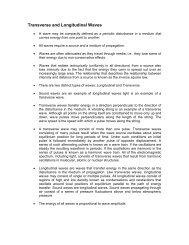
Electromagnetic Induction and Motional EMF
Electromagnetic Induction and Motional EMF
Electromagnetic Induction and Motional EMF

Create successful ePaper yourself
Turn your PDF publications into a flip-book with our unique Google optimized e-Paper software.
<strong>Electromagnetic</strong> <strong>Induction</strong> <strong>and</strong> <strong>Motional</strong> <strong>EMF</strong><br />
An <strong>EMF</strong> (Electromotive Force – a source of electrical potential) created by a<br />
changing magnetic field is known as an induced <strong>EMF</strong>.<br />
Induced <strong>EMF</strong>’s generate currents<br />
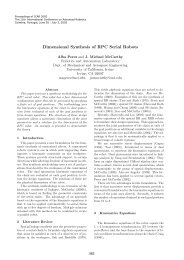
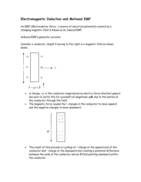
Consider a conductor, length l moving to the right in a magnetic field as shown<br />
below.<br />
⊗<br />
⊗<br />
l ⊗<br />
⊗<br />
v v<br />
⊗<br />
⊗<br />
v<br />
F<br />
v v<br />
= qv × B<br />
• A charge, +q in the conductor experiences an electric force directed upward<br />
(be sure to verify this for yourself) of magnitude qvB, due to the motion of<br />
the conductor through the field<br />
• The magnetic force causes the + charges in the conductor to move upward<br />
<strong>and</strong> the negative charges to move downward<br />
+ +<br />
+ +<br />
+ +<br />
E<br />
- -<br />
- -<br />
- -<br />
• The result of this process is a pileup of + charge at the upward end of the<br />
conductor <strong>and</strong> – charge at the downward end creating a potential difference<br />
between the ends of the conductor <strong>and</strong> an E field pointing downward within<br />
the conductor.
• The E field within the conductor produces a force, qE, also directed<br />
downward on positive charges. .<br />
• The force qvB causes polarization of the conductor <strong>and</strong> establishes a<br />
potential difference between the top <strong>and</strong> bottom of the conductor.<br />
• Due to this polarization an electric field is established within the conductor<br />
<strong>and</strong> any positive charge in this field experiences a force qE directed<br />
downward - which grows as charges accumulate at the ends of the conductor<br />
(it also continues to experience a force of qvB directed upwards as long as<br />
the conductor continues to move to the right).<br />
+ +<br />
+ +<br />
+ +<br />
v v v<br />
F = qvB<br />
- -<br />
- -<br />
- -<br />
v v<br />
F = qE<br />
• The accumulation of charges at the ends of the conductor continues until<br />
v v v<br />
qE = qvB . When this occurs the forces within the conductor are in<br />
equilibrium <strong>and</strong> no more accumulation of charges at the ends of the bar<br />
occurs.<br />
• The magnitude of the potential difference at equilibrium is:<br />
q / vB = qE / Q E = vB<br />
Recalling that V = Ed → V = El = vBl<br />
• The potential difference between the top <strong>and</strong> bottom of the conductor is<br />
vBl
What if we connect this polarized conductor, a source of electrical potential, to an<br />
external circuit?<br />
⊗<br />
⊗<br />
a<br />
∆s<br />
⊗<br />
⊗<br />
⊗<br />
I<br />
⊗<br />
⊗<br />
+<br />
⊗<br />
⊗<br />
v v<br />
l<br />
⊗<br />
⊗<br />
b<br />
⊗<br />
moving conductor <strong>and</strong> source of <strong>EMF</strong><br />
• A counterclockwise current is established due to the motion of the moving<br />
portion of the circuit.<br />
• The moving element is a source of <strong>EMF</strong>.<br />
• Charges move from lower to higher potential (as in other sources) in the<br />
moving segment, <strong>and</strong> from higher to lower throughout the rest of the<br />
circuit.<br />
• <strong>Motional</strong> <strong>EMF</strong>:<br />
ξ = vBl<br />
• If resistance (R) is negligible in the sliding segment ξ = V ab .<br />
• In real conductors ξ = V ab – IR where the potential drop is due to the<br />
resistance in real conductors.<br />
• The quantitative result here is applies generally to any source of electrical<br />
potential though the fundamental source of the <strong>EMF</strong> may be different.<br />
• In this particular example we had the moving conductor moving with a<br />
velocity v ⊥ to B (which was constant). In general the conductor could move<br />
in any plane (or B could vary) <strong>and</strong> still produce a motional <strong>EMF</strong> as long as a<br />
component of that plane is perpendicular to B.<br />
• The general expression for motional <strong>EMF</strong> is:<br />
ξ = vBlsinθ
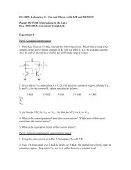
Example 1<br />
Compute the motional <strong>EMF</strong> <strong>and</strong> the current in the circuit for the following<br />
⊗<br />
⊗<br />
l = 0.1m<br />
⊗<br />
l<br />
⊗<br />
v<br />
v = 0.1m<br />
⋅ s<br />
−1<br />
⊗<br />
⊗<br />
R<br />
= 0. 01Ω<br />
B = 1. 0T<br />
The motional <strong>EMF</strong> is: ξ = vBlsinθ = (0.1m/s)(1.0T)(0.1m) = 0.01 volts<br />
The current in the loop is: I = ξ/R = 1 Amp<br />
This is essentially (schematically) how all electrical current is generated.<br />
Force <strong>and</strong> Work on a Current Loop<br />
In the previous example the current flowing through the circuit moves in the<br />
presence of an external B field that generates a force on the conducting elements<br />
of the circuit as shown below.<br />
F = Il × B = IBlsinθ = 0.1N (on the moving conductor)<br />
F<br />
I<br />
F<br />
⊗ ⊗ ⊗<br />
F<br />
F<br />
This magnetic force opposes<br />
the motion of the conductor<br />
In order to move the bar to the right at a constant velocity we must continue to<br />
apply a force to it that is equal in magnitude to IlB force. In other words we must<br />
do work on the system.
Recalling that work per unit time is power:<br />
or, equivalently:<br />
−1<br />
( 0.1m<br />
⋅ s ) = 0. watts<br />
P = Fv = (0.1N<br />
)<br />
01<br />
P = ξI = ( 0 .01V )( 1A) = 0. 01 watts<br />
The rate of energy conversion, ξI, equals the rate of mechanical energy input to<br />
the system.<br />
• We have conjured up a 0.01 watt electrical generator.<br />
• We would have to supply 0.01 watts of mechanical energy to move the<br />
conductor to produce 0.01 watts of electrical energy assuming 100%<br />
conversion.<br />
• Is this realistic? What is an obvious source of loss we have not computed?
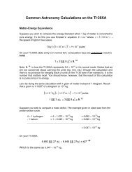
Example 2<br />
Consider the induced <strong>EMF</strong> from a conducting loop rotating as shown below with an<br />
angular velocity ω.<br />
z<br />
y<br />
v<br />
θ<br />
B<br />
ξ = v × B<br />
B<br />
θ<br />
x<br />
B<br />
ξ = v × B<br />
a<br />
v<br />
ω<br />
b/2<br />
First let’s examine the motional <strong>EMF</strong> produced by each side “a “of the loop.<br />
B<br />
⎛ b ⎞<br />
v = rω = ⎜ ⎟ ω<br />
⎝ 2 ⎠<br />
The velocity of side a.<br />
a<br />
ξ<br />
v<br />
b/2<br />
ξ = vBlsinθ = vBasinθ<br />
b<br />
= ω sinθ<br />
2 Ba
Since there are two a sides for this loop these two <strong>EMF</strong>’s add <strong>and</strong> the total <strong>EMF</strong> is:<br />
ξ = ωabB<br />
sinθ<br />
Notice that this <strong>EMF</strong> is directed in such a manner that it will cause current to flow<br />
through the a sides of the loop in the direction shown.<br />
On the “b” sides of the loop (top <strong>and</strong> bottom):<br />
B<br />
ξ<br />
v<br />
The magnetic forces on b sides are transverse to the conductor <strong>and</strong> do not<br />
contribute an <strong>EMF</strong> in a direction that produces current flow down the length of<br />
either side b<br />
The total <strong>EMF</strong> of the loop is therefore produced solely from the sides a.<br />
ξ total<br />
= ωabB<br />
sinθ<br />
Noting that ab = the area of the loop (A) <strong>and</strong> thatθ = wt :<br />
ξ total<br />
= ωAB sinωt<br />
= ωAB<br />
sinθ<br />
Note:<br />
• ξ varies sinusoidally with time.<br />
• ξ = ξ max when sin ωt = 1 this occurs when B<br />
is parallel to the plane of the loop <strong>and</strong> is<br />
perpendicular to µ <strong>and</strong> A<br />
• ξ max = ωAB<br />
• ξ = ξ max sin ωt<br />
B<br />
A<br />
µ r<br />
Basis for the construction of an electrical generator or alternator
The Alternator<br />
a<br />
slip ring<br />
B<br />
V ab<br />
+<br />
b<br />
ring rotates with<br />
the loop<br />
Notice current reverses direction in the loop as it turns. To see this look only at<br />
one segment of the loop as it rotates through 360 0 . The angles given are between<br />
the B <strong>and</strong> µ vectors.<br />
• θ = 0 0 → 90° I starts at zero <strong>and</strong> is increases to I max + (ccw)<br />
I<br />
• θ = 90 0 → 180 0 I begins at its maximum value <strong>and</strong><br />
decreases to zero, still + (ccw)<br />
t<br />
v<br />
I<br />
B<br />
B<br />
ξ<br />
v
• θ = 180 0 → 270 0 I starts at zero <strong>and</strong> is increasing – (cw)<br />
• θ = 270 0 → 360 0 I starts – I max <strong>and</strong> decreases to zero – (cw)<br />
v<br />
B<br />
B<br />
ξ<br />
v<br />
I<br />
So the direction of the current in side a reverses each half cycle as it does in the<br />
entire loop.<br />
Let’s modify this device as follows:<br />
V ab<br />
a<br />
B<br />
t<br />
b<br />
ring rotates with loop<br />
gap<br />
commutator<br />
At the angular positions where the current reverses itself, the connections to the<br />
external circuit are reversed. The <strong>EMF</strong> is always is the same direction but varies<br />
from 0 to some maximum value. This “half wave” may be easily rectified or<br />
converted from alternating to direct current.
Faraday’s Law<br />
Faraday’s Law relates changes in magnetic flux to <strong>EMF</strong><br />
d<br />
a<br />
∆s<br />
⊗<br />
A<br />
•<br />
⊗<br />
l +<br />
v<br />
⊗<br />
⊗<br />
⊗<br />
⊗<br />
c<br />
b<br />
• We have already looked at this circuit using the concept of magnetic force<br />
to produce a motional <strong>EMF</strong>.<br />
• We can also examine the change in magnetic flux through this circuit due to<br />
the increasing area. A change in magnetic flux produces <strong>EMF</strong>.<br />
• Changes in magnetic flux may be due to changes in the magnetic field<br />
strength or direction or a change in the area being penetrated by the<br />
magnetic field lines (which applies here?).<br />
• When the conductor moves to the right at distance ds, the area enclosed by<br />
r r<br />
abcd increases by: ∆ A = l∆s<br />
v v r r<br />
• The change in magnetic flux through abcd is: ∆Φ<br />
m<br />
= B ⋅ ∆A<br />
= Bl∆s<br />
cosθ<br />
r r<br />
Since B <strong>and</strong> A are parallel: ∆Φ<br />
m = Bl<br />
∆ s<br />
• Noting that l <strong>and</strong> B are constant, the time rate of change of the magnetic<br />
∆Φ<br />
m ∆s<br />
flux is:<br />
= Bl = Blv<br />
∆t<br />
∆t<br />
r r<br />
∆Φ<br />
m ∆( B ⋅ A)<br />
• Faraday’s Law: ξ = -<br />
∆t<br />
= −<br />
• Faraday’s Law of induction is valid for any circuit for which there is time<br />
varying magnetic flux, even circuits in which there is no evident motion.<br />
• The change in flux may be caused by a change in area with respect to time, a<br />
change in magnetic field with respect to time, or both<br />
• The negative sign is a matter of convention.<br />
∆Φ<br />
m<br />
• For multiple loops: ξ = -n<br />
∆t<br />
∆t
Consider a Transformer – a device that uses a change in magnetic flux to induce a<br />
current.<br />
B<br />
I<br />
Magnetic forces<br />
only influence<br />
charges in<br />
motion<br />
If I varies with time B also varies with time <strong>and</strong> an induced current appears in the<br />
winding on the right.<br />
Transformers are widely used for switching, electronic isolation <strong>and</strong> stepping<br />
voltages up or down.
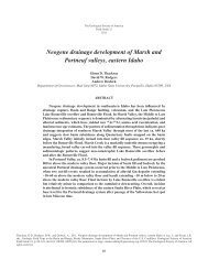
Example 3<br />
Consider a solenoid; n = 500 loops, r = 4 cm as shown below. The magnetic field is<br />
changing at a rate of 0.2T per second. Find the induced <strong>EMF</strong> in this solenoid<br />
B<br />
B<br />
B is increasing at<br />
B<br />
B<br />
−1 ∆B<br />
0.2T<br />
⋅ s = while the area remains unchanged.<br />
∆t<br />
The change in magnetic flux here is due to a changing magnetic field rather than a<br />
change in area penetrated by the magnetic field.<br />
Φ<br />
m<br />
=<br />
BA<br />
∆Φ<br />
∆t<br />
m<br />
=<br />
∆B<br />
A<br />
∆t<br />
A = π(.04m)² = 0.00503m²<br />
∆Φ<br />
Q<br />
∆t<br />
m<br />
=<br />
∆B<br />
A<br />
∆t<br />
= (.00503m<br />
)(0.2T<br />
⋅ s<br />
2 −1<br />
)<br />
.00101<br />
2 −1<br />
= T ⋅ m ⋅ s<br />
= .00101Wb<br />
⋅ s<br />
−1<br />
∆Φ<br />
ξ = -n<br />
∆t<br />
m<br />
= (500)(.00101T<br />
⋅ m ⋅ s<br />
2 −1<br />
) = 0.505 Volts<br />
Note that we are not really worried about the sign. We were not really told that<br />
∆B<br />
was positive or negative so worrying about the significance of the sign in the<br />
∆t<br />
answer makes no sense.<br />
Which direction does the induced current flow in the coils? (bottom to top)
What if the situation had looked like this:<br />
θ = 30°<br />
B<br />
We want ⊥ component of B so B(cos 30°) = B ⊥ = B. So we would multiply the<br />
result above by cos 30°
B v v v w<br />
Example 4<br />
Let’s look again at the induced <strong>EMF</strong> produced by the same rotating loop we looked<br />
at earlier.<br />
z<br />
y<br />
v<br />
θ<br />
B<br />
ξ = v × B<br />
B<br />
θ<br />
x<br />
B<br />
Recall:<br />
ξ = v × B<br />
a<br />
v<br />
ω<br />
b/2<br />
B<br />
θ<br />
v<br />
B<br />
r<br />
F m<br />
r v<br />
= qv × B<br />
Notice that the cross product in this expression “picks off” components of v<br />
r v<br />
perpendicular to B. In this particular configuration v × B = 0 (F m <strong>and</strong> I at minimum<br />
values) but when the loop rotates 90 0 both I <strong>and</strong> F m are at a maximum value.<br />
Based on evaluating the time varying cross product (with a few twists <strong>and</strong> turns) we<br />
arrived at:<br />
b<br />
ξ = vBl sinθ → ξ = 2 ω a Bsinθ<br />
= ωABsinθ<br />
= ωABsinωt<br />
2
Now consider evaluating the induced <strong>EMF</strong> with Faraday’s Law.<br />
A v<br />
r<br />
B v<br />
w<br />
B v<br />
v v<br />
The magnetic flux through the loop is Φ<br />
m<br />
= B ⋅ A = BAcosθ<br />
. Notice that the dot<br />
product in this expression “picks off” parallel components of B <strong>and</strong> A. In this<br />
particular configuration the maximum area of the loop is exposed to the B field so<br />
flux through the loop is at a maximum value.<br />
The instantaneous flux through the loop is<br />
v v<br />
Φ = BA cos θ = B ⋅ A<br />
But the loop is rotating with an angular velocity ω so the flux is changing as a<br />
function of ω . Recalling that θ = ωt<br />
:<br />
Φ<br />
m<br />
= BAcosωt<br />
Faraday’s Law yields (with a little arithmetic massage):<br />
∆Φ<br />
ξ = −<br />
∆t<br />
m<br />
= ωBAsinωt<br />
= ωBAsinθ<br />
Notice that this is the same result as derived earlier.
Lenz’s Law<br />
Lenz’s Law is an alternative method for determining the direction of an induced<br />
current.<br />
The direction of an induced current is such as to oppose the cause producing it.<br />
“Causes” may include:<br />
• motion of a conductor in a B field<br />
• change in flux<br />
Lenz’s Law states that any induced <strong>EMF</strong> opposes either the motion causing the<br />
induced current or the change in flux causing the induced current. Conservation of<br />
energy is the underlying principle.<br />
Examples<br />
Moving conductor in a B field<br />
x<br />
I<br />
x<br />
x<br />
x<br />
x<br />
x<br />
x<br />
x<br />
v<br />
F<br />
v v<br />
= qv × B<br />
F<br />
The induced <strong>EMF</strong> opposes the motion of<br />
the conductor creating the current
Rotating loop in a B field.<br />
B v<br />
v<br />
v v × B<br />
I<br />
v v<br />
× B<br />
ω<br />
The velocity here is<br />
of the current not the<br />
tangential velocity of<br />
the loop.<br />
Notice that the induced <strong>EMF</strong><br />
creates a current which produces a<br />
force that in turn opposes rotation<br />
of loop.<br />
Two solenoids in motion with respect to each other:<br />
a<br />
R<br />
b<br />
+<br />
ε<br />
_<br />
1) ξ increasing<br />
N<br />
repulsive<br />
N<br />
Current must be CCW i.e.<br />
a → b<br />
2) ξ decreasing<br />
S<br />
Current must be CW<br />
attractive<br />
N
Summary - Induced <strong>EMF</strong><br />
• ξ = vBl<br />
Works for a conductor moving through a stationary B field<br />
− ∆Φ<br />
m<br />
• ξ = Works for B fields that change with time<br />
∆t<br />
Since motion is relative the second method always works<br />
For coils of N turns:<br />
∆Φ<br />
m<br />
ξ = −N<br />
∆t
Applications of Induced <strong>EMF</strong>’s<br />
Transformers are devices that exploit the constantly changing magnetic flux of<br />
alternating currents to induce currents in devices that do not physically touch.<br />
Transformers are widely used for both electronic isolation (for low electronic noise<br />
<strong>and</strong> for safety) <strong>and</strong> to step up or step down AC voltages<br />
Some advantages of AC over DC:<br />
• Easier to step up <strong>and</strong> down<br />
• Easier to transmit<br />
• Can use high voltage & low current to reduce power losses in<br />
transmission lines<br />
Most transmission lines carry about 500kV which must be stepped down (converted<br />
to lower voltages) for household or office operation.<br />
Primary<br />
Secondary<br />
V<br />
V<br />
S<br />
P<br />
=<br />
N<br />
N<br />
S<br />
P<br />
⇒<br />
The transformer equation<br />
N<br />
N<br />
S<br />
S<br />
> N<br />
< N<br />
P<br />
P<br />
⇒<br />
⇒<br />
Step up transformer<br />
Step down transformer<br />
• It is important to note that power in = power out.<br />
• Transformers trade voltage for current<br />
V<br />
P S P<br />
V<br />
P<br />
I<br />
P<br />
= VS<br />
I<br />
S<br />
→ = → =<br />
VS<br />
I<br />
P<br />
N<br />
S<br />
I<br />
N<br />
I<br />
I<br />
S<br />
P
A transducer is a device that converts mechanical motion to an electrical signal or<br />
vice versa. Transducers generally work by exploiting the behavior of conductors in<br />
magnetic flux.<br />
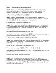
The Electric Guitar<br />
String<br />
Nickel<br />
To preamplifier<br />
Permanent<br />
Magnet<br />
To preamplifier<br />
Coil Windings<br />
• Virtually all electric guitars use electromagnetic pickups<br />
• Most guitars have at least two pickups for each string <strong>and</strong> some have three.<br />
• Pickups are positioned at different locations under the string so that each is<br />
sensitive to different harmonics produced by the vibrating string.<br />
• Electric guitar strings are generally made of nickel – a material easily<br />
magnetized.<br />
• The pickup consists of a coil of wire with a permanent magnet inside the coil.<br />
• The magnet in the pickup induces a magnetic field in the string as shown<br />
above<br />
• The magnetic field of the string vibrates with the string as it is plucked<br />
• The change in magnetic flux due to the vibration of the field lines across the<br />
coil windings produces an oscillating change if <strong>EMF</strong> in the coil<br />
• An oscillating current is produced at the same frequency as that of the<br />
vibrating string<br />
• The <strong>EMF</strong> produced is very weak (a few microvolts) <strong>and</strong> must be amplified to<br />
a level of a few millivolts (line level) in order to drive any subsequent<br />
electronic devices. The device that does this is referred to as a preamp.<br />
• Preamps are also responsible for modifying the tonal characteristics of the<br />
signal.<br />
• In order to drive a loudspeaker the signal must be amplified again by a power<br />
amplifier to a level of typically 10 – 70 volts.<br />
• A loudspeaker is another transducer that converts electricity to mechanical<br />
motion which in turn produces an acoustic wave
Loudspeakers <strong>and</strong> Microphones<br />
• We have previously learned how a vibrating object such as a guitar string<br />
produces an acoustic wave. We have also seen how acoustic waves propagate<br />
through the air <strong>and</strong> how the energy in acoustic waves can be transferred to<br />
an object some distance from the source of the wave causing it to vibrate at<br />
the same frequency as the source.<br />
• Sound waves consist of very small displacement amplitudes <strong>and</strong> minute<br />
fluctuations of pressure. When sound waves impinge upon a surface they<br />
impart very small energy pluses to the incident material because their<br />
displacement amplitudes are small.<br />
• Because sound waves suffer losses from several sources they must be<br />
amplified to travel long distances <strong>and</strong> still arrive at the source with<br />
sufficient amplitude (volume) for clarity. This is the primary purpose of a<br />
sound system.<br />
• In order to amplify an acoustic wave we must find a way of converting it to<br />
an electrical signal. Transducers are devices that may be used to convert<br />
acoustic waves to electrical signals.<br />
• A very common type of transducer used in converting acoustic signals to<br />
electrical signals is known as a linear electromagnetic motor. The guitar<br />
pickup is one example of a linear electromagnetic motor.<br />
• Linear electromagnetic motor are based on electromagnetic induction. The<br />
diagram below contains a cross-sectional view of a simplified linear<br />
electromagnetic motor.
• This particular L.E.M. consists of an iron magnet <strong>and</strong> a coil of wire (normally<br />
copper) attached to a diaphragm.<br />
• As a sound wave impinges upon the diaphragm it vibrates at the same<br />
frequency as the incoming wave.<br />
• The greater the SPL (amplitude) of the incident wave, the greater the<br />
amplitude of vibration imparted to the diaphragm <strong>and</strong> attached wire coil.<br />
• As the coil moves back <strong>and</strong> forth within the magnetic field of the fixed<br />
magnet an alternating current is induced that changes direction each time<br />
the coil changes direction.<br />
• The larger the amplitude of oscillations, the stronger the induced voltage.<br />
• Notice that as long as the movement of the diaphragm does not exceed the<br />
elastic limits of the mounting system it behaves exactly like a simple<br />
harmonic oscillator. The waveform generated is therefore sinusoidal.<br />
• This is generally how a dynamic microphone operates. In order to contain the<br />
infrastructure needed to create this transformation in a compact package it<br />
is necessary to limit the size of the magnet <strong>and</strong> wire coil. Large diaphragms<br />
<strong>and</strong> massive wire coils, due to their large inertia, will not vibrate as easily as<br />
smaller diaphragms <strong>and</strong> light coils unless the SPL of the incoming wave is<br />
extremely high.<br />
• Because of inertial limitations most dynamic microphones produce extremely<br />
low-voltage signals, typically a few microvolts, which must be amplified by<br />
other electronic devices in order to gain enough strength to drive a<br />
loudspeaker.<br />
• There are other devices capable of converting an acoustic signal to an<br />
alternating current including capacitor, piezoelectric <strong>and</strong> ribbon transducers.<br />
• Loudspeakers are linear electromagnetic motors that are essentially<br />
microphones in reverse, i.e., loudspeakers convert electrical signals to<br />
acoustic waves.<br />
• In most loudspeakers alternating current flowing through a wire coil in the<br />
presence of a fixed magnetic field causes the coil to oscillate at the<br />
frequency of the source signal. If the coil is attached to a diaphragm,<br />
acoustic waves will be produced as the diaphragm vibrates back in forth in<br />
air.