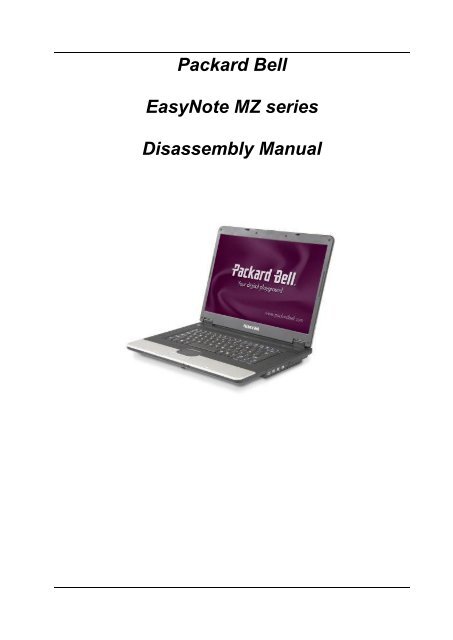
Packard Bell EasyNote MZ series Disassembly Manual
Create successful ePaper yourself
Turn your PDF publications into a flip-book with our unique Google optimized e-Paper software.
<strong>Packard</strong> <strong>Bell</strong><br />
<strong>EasyNote</strong> <strong>MZ</strong> <strong>series</strong><br />
<strong>Disassembly</strong> <strong>Manual</strong>
Table of Contents<br />
Overview ..................................................................................................................3<br />
Technician Notes......................................................................................................3<br />
<strong>Disassembly</strong> Instructions..........................................................................................3<br />
Reassembly Instructions ..........................................................................................3<br />
Required Tools.........................................................................................................3<br />
Battery......................................................................................................................4<br />
Memory ....................................................................................................................4<br />
Wireless LAN adapter (Mini-PCI or Mini PCI-Express card).....................................6<br />
Hard disk ..................................................................................................................6<br />
Optical drive .............................................................................................................7<br />
Keyboard..................................................................................................................9<br />
LCD Panel Assembly..............................................................................................11<br />
Topcover and touchpad..........................................................................................12<br />
Mainboard ..............................................................................................................13<br />
Modem (optional) ...................................................................................................13<br />
USB Board .............................................................................................................13<br />
CPU and CPU fan ..................................................................................................14<br />
DC Jack..................................................................................................................15<br />
Speakers ................................................................................................................15<br />
LCD Panel..............................................................................................................15<br />
Wireless LAN antenna............................................................................................17<br />
Inverter board.........................................................................................................17<br />
Reassembly Notes .................................................................................................18<br />
Notice .....................................................................................................................18<br />
<strong>EasyNote</strong> <strong>MZ</strong> <strong>Disassembly</strong> <strong>Manual</strong> 2
Overview<br />
This document contains step-by-step disassembly instructions for the <strong>EasyNote</strong> <strong>MZ</strong><br />
<strong>series</strong>. The instructions are illustrated where necessary with images of the part of the<br />
device that is being removed or disassembled.<br />
<strong>Packard</strong> <strong>Bell</strong> reserves the right to make changes to the <strong>EasyNote</strong> <strong>MZ</strong> <strong>series</strong> without<br />
notice.<br />
Technician Notes<br />
Only technicians authorized by <strong>Packard</strong> <strong>Bell</strong> B.V. should attempt to repair this<br />
equipment. All troubleshooting and repair procedures are detailed to allow only<br />
subassembly/module level repair. Because of the complexity of the individual boards<br />
and subassemblies, no one should attempt to make repairs at the component level or to<br />
make modifications to any printed wiring board. Improper repairs can create a safety<br />
hazard. Any indication of component replacement or printed wiring board modifications<br />
may void any warranty or exchange allowances.<br />
<strong>Disassembly</strong> Instructions<br />
When disassembling the unit, follow these general rules:<br />
• Turn off the power and disconnect all cables.<br />
• Label all removed connectors. Note where the connector goes and in what<br />
position it was installed.<br />
• Do not disassemble the unit into parts that are smaller than those specified in<br />
the instructions.<br />
Reassembly Instructions<br />
Reassembly is the reverse of the disassembly process. Use care to ensure that all<br />
cables and screws are returned to their proper positions. Check that no tools or any<br />
loose parts have been left inside the product. Check that everything is properly installed<br />
and tightened.<br />
Required Tools<br />
All disassembly procedures can be performed using the following tools:<br />
• Phillips (#1 bit) screwdriver<br />
• Small flat blade screwdriver<br />
<strong>EasyNote</strong> <strong>MZ</strong> <strong>Disassembly</strong> <strong>Manual</strong> 3
Battery<br />
1. Push the two sliders outwards and pull out the battery.<br />
Fig. 1 The bottom of the notebook.<br />
Memory<br />
1. Remove battery as described above.<br />
2. Unlock the 2 screws of the memory cover. Note that the screws will not<br />
come loose completely; they will stay attached to the cover.<br />
Fig. 2 The bottom of the notebook.<br />
<strong>EasyNote</strong> <strong>MZ</strong> <strong>Disassembly</strong> <strong>Manual</strong> 4
3. Lift the door out.<br />
Fig. 3 The memory compartment.<br />
4. Push aside the clips securing the memory module.<br />
5. Lift the module from the slot.<br />
Fig. 4 The memory module<br />
<strong>EasyNote</strong> <strong>MZ</strong> <strong>Disassembly</strong> <strong>Manual</strong> 5
Note: In case there are 2 modules built in, you will have to remove the top module before<br />
removing the bottom module.<br />
Wireless LAN Adapter (Mini-PCI or Mini PCI-Express)<br />
1. Remove the battery as described above.<br />
2. Unlock the 2 screws of the add-on card cover. Note that the screws will<br />
not come loose completely; they will stay attached to the cover.<br />
See Fig. 2.<br />
3. Lift the door out.<br />
4. Disconnect the WLAN antennas from the card. Make a note for each<br />
cable whether it is connected to ‘main’ or ‘aux’.<br />
5. For mini-PCI (<strong>EasyNote</strong> <strong>MZ</strong>35 / <strong>MZ</strong>36): Push aside the two clips<br />
securing the WLAN adapter card.<br />
Fig. 5 The WLAN module.<br />
6. For mini-PCI Express (<strong>EasyNote</strong> <strong>MZ</strong>45): remove the two screws<br />
securing the WLAN adapter.<br />
7. Pull the card from its slot.<br />
Hard Disk Drive<br />
1. Remove the battery as described above.<br />
2. Unlock the 2 screws of the HDD cover. Note that the screws will not<br />
come loose completely; they will stay attached to the cover.<br />
See Fig. 2.<br />
3. Lift the door out.<br />
4. Pull the hard disk loose from its connector.<br />
<strong>EasyNote</strong> <strong>MZ</strong> <strong>Disassembly</strong> <strong>Manual</strong> 6
5. Lift out the hard disk.<br />
6. Remove the 4 screws from the bracket.<br />
Fig. 6 The hard disk drive.<br />
7. Lift the hard disk from the bracket.<br />
Optical Drive<br />
1. Remove the battery as described above.<br />
2. Remove the screw securing the optical drive. See Fig. 2.<br />
3. Use the emergency eject-function of the optical drive to open the tray.<br />
4. Pull the optical drive out.<br />
<strong>EasyNote</strong> <strong>MZ</strong> <strong>Disassembly</strong> <strong>Manual</strong> 7
Fig. 7 The optical drive.<br />
5. Remove the 2 screws to and take away the optical drive bracket.<br />
Fig. 8 The optical drive bracket.<br />
<strong>EasyNote</strong> <strong>MZ</strong> <strong>Disassembly</strong> <strong>Manual</strong> 8
6. Remove the bezel of the optical: it is clicked in place. Use a small<br />
flathead screwdriver to push the 2 clips loose. After that, take away the<br />
bezel from the drive.<br />
Fig. 9 The optical drive bezel.<br />
Keyboard<br />
1. Remove the battery as described above.<br />
2. Remove the 2 screws below the hinge covers of the LCD.<br />
Fig. 10 Hinge cover screw.<br />
3. Remove the keyboard cover. If needed, you can carefully pry the<br />
keyboard cover loose with a flathead screwdriver in the hinge covers.<br />
Fig. 11 The keyboard cover.<br />
4. On the bottom base, remove the 2 screws in the memory compartment.<br />
<strong>EasyNote</strong> <strong>MZ</strong> <strong>Disassembly</strong> <strong>Manual</strong> 9
Fig. 12 The memory compartment.<br />
5. Lift the keyboard.<br />
6. Disconnect the keyboard flatcable.<br />
Fig. 13 The bottom of the notebook.<br />
7. Remove the keyboard.<br />
<strong>EasyNote</strong> <strong>MZ</strong> <strong>Disassembly</strong> <strong>Manual</strong> 10
LCD Panel Assembly<br />
1. Remove the battery and keyboard cover as described above (up to<br />
step 3).<br />
2. Disconnect the WLAN antenna as described under “WLAN Adapter”<br />
(up to step 4).<br />
3. Clear the wireless antenna (it is taped and clipped in place).<br />
4. Disconnect the LCD cable.<br />
5. Remove the 4 screws in the hinges.<br />
Fig. 14 The WLAN antenna and hinge screws.<br />
6. Remove the 2 screws in the bottom base.<br />
Fig. 15 The bottom of the notebook.<br />
7. Put the LCD panel in a 90 degree angle with the base unit and lift the<br />
LCD panel out.<br />
<strong>EasyNote</strong> <strong>MZ</strong> <strong>Disassembly</strong> <strong>Manual</strong> 11
Top Cover and Touchpad<br />
1. Follow all steps above to remove the battery, keyboard, LCD panel,<br />
hard disk and optical drive.<br />
2. Remove the 6 screws from the top cover.<br />
3. Disconnect the flatcable of the touchpad.<br />
Note: the flatcable only needs to be pulled out, it is not secured.<br />
Fig. 16 The touchpad cover.<br />
4. Remove all remaining screws from the bottom base (17x).<br />
5. Take away the top cover.<br />
Fig. 17 The bottom of the notebook.<br />
<strong>EasyNote</strong> <strong>MZ</strong> <strong>Disassembly</strong> <strong>Manual</strong> 12
Note: The touchpad is shipped as part of the top cover and does not require further<br />
disassembly.<br />
Mainboard<br />
1. Follow all steps outlined above.<br />
2. Disconnect the power cable and USB port cable via the memory<br />
compartment and wireless LAN adapter compartment.<br />
3. Remove the two screws in the mainboard.<br />
Fig. 18 The mainboard.<br />
4. Remove the two hex-bolts adjacent to the VGA port.<br />
5. Lift out the motherboard.<br />
6. Remove the CPU fan and CPU as described below.<br />
Modem (optional)<br />
Note: The modem is part of the motherboard.<br />
USB Board<br />
1. Follow all steps to remove the top cover.<br />
2. Disconnect the cable from the USB board.<br />
3. Remove the two screws securing the USB board.<br />
<strong>EasyNote</strong> <strong>MZ</strong> <strong>Disassembly</strong> <strong>Manual</strong> 13
Fig. 19 The USB board.<br />
4. Lift out the USB board.<br />
Note: To replace the cable to the USB board, the motherboard needs to be removed.<br />
CPU and CPU fan<br />
1. Follow all steps to remove the mainboard.<br />
2. Disconnect the power cable of the fan.<br />
3. Remove the 2 screws of the north-bridge heatsink.<br />
4. Remove the 4 screws of the CPU heatsink, in the designated order (1<br />
to 4 engraved in metal clips).<br />
Fig. 20 The heatsinks for the CPU and north-bridge.<br />
<strong>EasyNote</strong> <strong>MZ</strong> <strong>Disassembly</strong> <strong>Manual</strong> 14
5. Lift out the CPU fan.<br />
6. To remove the CPU from the socket, turn the screw in the socket 180<br />
degrees to release the CPU.<br />
7. Lift out the CPU.<br />
DC Jack<br />
1. Follow all steps to remove the mainboard.<br />
2. Remove the two screws grounding the DC jack cable (one on DC<br />
board, one near battery connector).<br />
Fig. 21 The DC jack.<br />
3. Lift the DC jack straight up out of the bracket.<br />
Speaker Assembly<br />
1. Follow all steps to remove the top cover.<br />
2. Disconnect the speaker cable from the mainboard.<br />
3. Remove the 4 screws securing the 2 speakers.<br />
Fig. 22 The speaker assembly.<br />
4. Release the speaker cables from the clips.<br />
5. Lift out the speakers<br />
Note The two speakers are one part; they cannot be replaced individually.<br />
LCD Panel<br />
1. Follow all steps to remove the LCD Panel Assembly.<br />
2. Remove the 6 rubber stoppers in the LCD bezel.<br />
3. Remove the 6 screws.<br />
<strong>EasyNote</strong> <strong>MZ</strong> <strong>Disassembly</strong> <strong>Manual</strong> 15
Fig. 23 The LCD panel assembly.<br />
4. Take off the bezel (clicked in place).<br />
5. Disconnect the cables from the inverterboard.<br />
6. Remove the 6 screws of the LCD panel.<br />
Fig. 24 LCD panel assembly after top cover removal.<br />
7. Lift out the LCD panel.<br />
8. Remove the 6 screws of the LCD panel brackets, 3 on each side of the<br />
panel.<br />
9. Disconnect the LCD cable.<br />
<strong>EasyNote</strong> <strong>MZ</strong> <strong>Disassembly</strong> <strong>Manual</strong> 16
Fig. 25 The LCD cable.<br />
Wireless LAN Antenna<br />
1. Follow the steps for the LCD panel up to step 4.<br />
2. Remove the two screws on the top of the LCD panel.<br />
Fig. 26 The wireless LAN antenna.<br />
3. Remove the antenna. Note that it is taped in place.<br />
Inverter Board<br />
1. Follow the steps for the LCD panel up to step 5.<br />
2. The inverterboard is glued in place. Gently tear it out.<br />
<strong>EasyNote</strong> <strong>MZ</strong> <strong>Disassembly</strong> <strong>Manual</strong> 17
Reassembly Notes<br />
When reassembling the device, please take notice of the order in which<br />
the parts can be put back and reattached.<br />
Notice<br />
The information in this guide is subject to change without notice.<br />
This guide contains information protected by copyright. No part of this guide<br />
may be photocopied or reproduced in any form or by any means without prior<br />
written consent from <strong>Packard</strong> <strong>Bell</strong> B.V.<br />
PACKARD BELL B.V. SHALL NOT BE LIABLE FOR TECHNICAL OR<br />
EDITORIAL ERRORS OR OMISSIONS CONTAINED HEREIN; NOR FOR<br />
INCIDENTAL OR CONSEQUENTIAL DAMAGES RESULTING FROM THE<br />
FURNISHING, PERFORMANCE, OR USE OF THIS MATERIAL.<br />
Copyright © 2007 <strong>Packard</strong> <strong>Bell</strong> B.V. All rights reserved.<br />
First Edition: April 2007<br />
Version: 1.0<br />
<strong>Packard</strong> <strong>Bell</strong> B.V.<br />
<strong>EasyNote</strong> <strong>MZ</strong> <strong>Disassembly</strong> <strong>Manual</strong> 18


