Grade Crossing Pro - Logic Rail Technologies
Grade Crossing Pro - Logic Rail Technologies
Grade Crossing Pro - Logic Rail Technologies

Create successful ePaper yourself
Turn your PDF publications into a flip-book with our unique Google optimized e-Paper software.
LOGIC<br />
RAIL<br />
TM<br />
"Sophisticated<br />
Model <strong>Rail</strong>road<br />
Electronics"<br />
TECHNOLOGIES<br />
21175 Tomball Pkwy Phone: (281) 251-5813<br />
Suite 287<br />
email: info@logicrailtech.com<br />
Houston, TX 77070 http://www.logicrailtech.com<br />
<strong>Grade</strong> <strong>Crossing</strong> <strong>Pro</strong><br />
Application Note: Interfacing to a Tam<br />
Valley Depot Singlet servo driver board<br />
for servo-controlled crossing gates<br />
Revised 7/29/13<br />
Introduction<br />
This application note describes how to connect a Tam Valley Depot (TVD) Singlet servo driver board to the <strong>Grade</strong> <strong>Crossing</strong><br />
<strong>Pro</strong> (GCP or GCP-IR, hereafter just referred to as simply GCP). You might choose to use servo motors to control your<br />
crossing gate arms rather than a slow motion motor such as the Circuitron Tortoise. Specific details on connecting the servo<br />
motor to the TVD board and programming it are NOT provided here; refer to the instructions that are provided by TVD! This<br />
application note does not provide details on wiring your crossing signals – these details are provided in the GCP instructions!<br />
This application DOES include wiring for an optional grade crossing bell module.<br />
GCP with a TVD Singlet servo driver board (no bell module)<br />
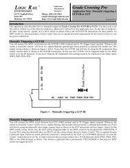
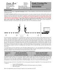
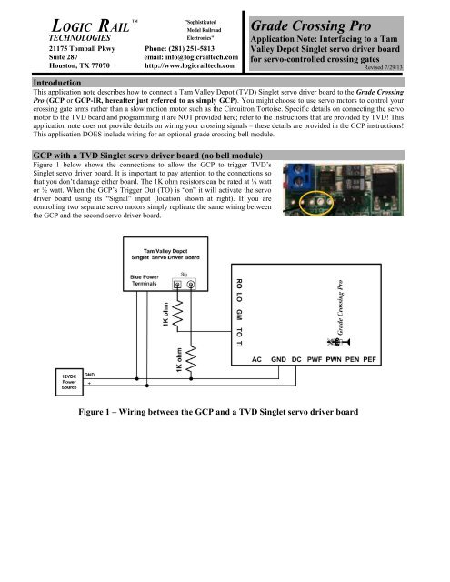
Figure 1 below shows the connections to allow the GCP to trigger TVD’s<br />
Singlet servo driver board. It is important to pay attention to the connections so<br />
that you don’t damage either board. The 1K ohm resistors can be rated at ¼ watt<br />
or ½ watt. When the GCP’s Trigger Out (TO) is “on” it will activate the servo<br />
driver board using its “Signal” input (location shown at right). If you are<br />
controlling two separate servo motors simply replicate the same wiring between<br />
the GCP and the second servo driver board.<br />
Figure 1 – Wiring between the GCP and a TVD Singlet servo driver board
1<br />
Tr<br />
k<br />
GCP with a TVD Singlet servo driver board and ITT <strong>Grade</strong> <strong>Crossing</strong> Bell sound module<br />
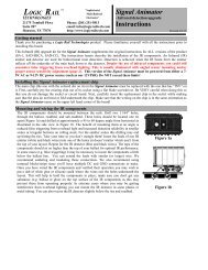
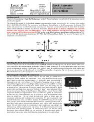
Figure 2 below shows the connections to allow the GCP to trigger TVD’s Singlet servo driver board AND the ITT <strong>Grade</strong><br />
<strong>Crossing</strong> Bell sound module. It is important to pay attention to the connections so that you don’t damage any of the boards.<br />
The 1K ohm resistors can be rated at ¼ watt or ½ watt. Make sure you connect the diodes with the proper polarity as shown!<br />
When the GCP’s Trigger Out (TO) is “on” it will activate the servo driver board using its “Signal” input along with<br />
completing the bell module’s power input. If you are controlling two separate servo motors simply replicate the same wiring<br />
between the GCP and the second servo driver board; you don’t need a 3 rd diode; just connect another 1K resistor to the<br />
positive (+) side of the existing diode.<br />
ITT HQ Series 2010<br />
HQ300-x<br />
<strong>Grade</strong> Bell<br />
SPEAKER MOM/LOOP POWER<br />
Diodes: 1N4001<br />
(Radio Shack #276-1101)<br />
-<br />
+<br />
12VDC<br />
Power<br />
Source<br />
GND<br />
+<br />
Tam Valley Depot<br />
Singlet Servo Driver Board<br />
Blue Power<br />
Terminals<br />
1K ohm<br />
Sig<br />
1K ohm<br />
Diode<br />
Diode<br />
RO LO GM TO TI<br />
AC<br />
CROSSI<br />
NG<br />
RAIL<br />
ROAD<br />
<strong>Grade</strong> <strong>Crossing</strong> <strong>Pro</strong><br />
GND DC PWF PWN PEN PEF<br />
ac<br />
Figure 2 – Wiring between the GCP, a TVD Singlet servo driver board, and ITT bell module<br />
Technical Support<br />
If you need further assistance with this application please do not hesitate to contact us by phone, mail and email; our contact<br />
information can be found on the top of Page 1.