Grade Crossing Pro - Logic Rail Technologies
Grade Crossing Pro - Logic Rail Technologies
Grade Crossing Pro - Logic Rail Technologies

Create successful ePaper yourself
Turn your PDF publications into a flip-book with our unique Google optimized e-Paper software.
LOGIC<br />
RAIL<br />
TM<br />
"Sophisticated<br />
Model <strong>Rail</strong>road<br />
Electronics"<br />
TECHNOLOGIES<br />
21175 Tomball Pkwy Phone: (281) 251-5813<br />
Suite 287<br />
email: info@logicrailtech.com<br />
Houston, TX 77070 http://www.logicrailtech.com<br />
<strong>Grade</strong> <strong>Crossing</strong> <strong>Pro</strong><br />
Application Note: Manually triggering a<br />
GCP-IR or GCP<br />
Revised 8/4/12<br />
Introduction<br />
This application note describes how to manually trigger the <strong>Grade</strong> <strong>Crossing</strong> <strong>Pro</strong> (GCP-IR or GCP). You may wish to do<br />
this with or without use of the detector method (i.e. photocell or infrared). In this application note, for the sake of simplicity,<br />
all other wiring (power, signals, etc) is NOT shown so please refer to the GCP/GCP-IR instructions for those details. An<br />
SPST on/off (i.e. non-momentary) switch is used. There are no special electrical requirements for the switch as this is a very<br />
low power connection.<br />
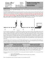
Manually Triggering a GCP-IR<br />
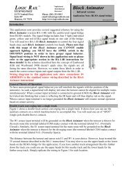
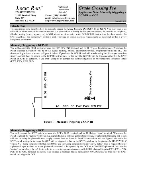
You will connect the SPST switch between the GCP-IR’s GND terminal and its TI (Trigger Input) terminal. Whenever the<br />
switch is closed the “action” will be on (i.e. signals flashing, optional gate motor powered, or optional bell module on). This<br />
simple wiring scheme is shown in Figure 1 below. If you have the GCP-IR and will also be using the IR components then<br />
simply connect them as shown in the GCP-IR instructions. In this way the GCP-IR will be triggered either by the SPST<br />
switch or by the IR detectors. If you aren’t using the IR components then nothing needs to be connected to the sensor inputs<br />
(PWF, PWN, PEN, PEF).<br />
CROSSING<br />
RAIL<br />
ROAD<br />
Figure 1 – Manually triggering a GCP-IR<br />
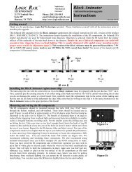
Manually Triggering a GCP<br />
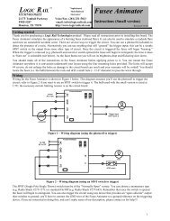
You will connect the SPST switch between the GCP’s GND terminal and its TI (Trigger Input) terminal. Whenever the<br />
switch is closed the “action” will be on (i.e. signals flashing, optional gate motor powered, or optional bell module on). If you<br />
will also be using the photocells then simply connect them as shown in the GCP instructions and use Figure 1 above for the<br />
SPST switch wiring. In this way the GCP will be triggered either by the SPST switch or by the photocells. HOWEVER, if<br />
you are NOT using the photocells then you MUST use the wiring scheme shown in Figure 2 below! This is required because<br />
a photocell input without an actual photocell connected is interpreted by the GCP as a COVERED photocell. As such the<br />
“action” would always be on! So, in order to prevent this you must connect ALL FOUR photocell inputs (PWF, PWN, PEN,<br />
PEF) to the GND terminal as shown. This mimics a photocell that is permanently UNCOVERED so that only the SPST<br />
switch can trigger the GCP.
RO LO GM TO TI<br />
RAIL<br />
ROAD<br />
CROSSING<br />
Tr<br />
ac<br />
<strong>Grade</strong> <strong>Crossing</strong> <strong>Pro</strong><br />
1<br />
k<br />
AC<br />
GND DC PWF PWN PEN PEF<br />
Figure 2 – Manually triggering a GCP without photocells connected<br />
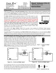
Trigger the <strong>Grade</strong> <strong>Crossing</strong> <strong>Pro</strong> using other methods<br />
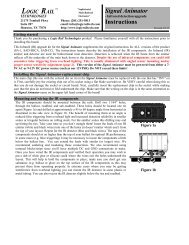
You may wish to trigger the <strong>Grade</strong> <strong>Crossing</strong> <strong>Pro</strong> using an external electronic circuit rather than a mechanical on/off switch. This<br />
is also possible using a wiring scheme similar to what’s shown previously. You will need an “open-collector” type of connection<br />
that when “active” serves the same purpose as an SPST switch. Figure 3 below shows an example of this where the controlling<br />
circuit has an NPN transistor output. Also refer to a portion of Figure 2 above if you’re using the GCP without photocells.<br />
RO LO GM TO TI<br />
RAIL<br />
ROAD<br />
Tr<br />
ac<br />
<strong>Grade</strong> <strong>Crossing</strong> <strong>Pro</strong><br />
1<br />
k<br />
CROSSING<br />
External<br />
Electronic<br />
Circuit<br />
AC<br />
GND DC PWF PWN PEN PEF<br />
Figure 3 – Manually triggering a GCP from another electronic circuit<br />
Technical Support<br />
If you need further assistance with this application please do not hesitate to contact us by phone, mail and email; our contact<br />
information can be found on the top of Page 1.