G-1010 - Vibration Management Corporation
G-1010 - Vibration Management Corporation
G-1010 - Vibration Management Corporation

You also want an ePaper? Increase the reach of your titles
YUMPU automatically turns print PDFs into web optimized ePapers that Google loves.
TEL: +1-713-983-VIMCO<br />
+1-713-983-8462<br />
FAX: +1-713-983-9933<br />
A
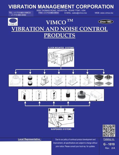
INTRODUCTION<br />
VIMCO is pleased and excited to release our newest marketing literature: the G-<strong>1010</strong> booklet. This booklet provides<br />
condensed information on our entire range of vibration and noise isolation products. The information includes<br />
product features, application information, dimensional data and model selection tables. We expect this booklet to be<br />
an invaluable resource for engineers, representatives, distributors and contractors.<br />
One new tool that we are introducing in this latest literature is our exclusive isolator 5 star rating system . <strong>Vibration</strong><br />
isolation efficiency is directly related to the amount of deflection (compression) of the isolating element. The isolation<br />
efficiency chart below illustrates the theoretical relationship between isolation efficiency, disturbing frequency and<br />
isolator static deflection<br />
Disturbing frequency is the frequency of vibration produced by an unbalanced,<br />
rotating or reciprocating movement in mass.<br />
Natural frequency is the number of complete cycles of oscillation a mass will vibrate<br />
in a given unit of time if a force displaces it from its equilibrium position and allows it<br />
to vibrate freely.<br />
Static deflection is the distance an isolator will deflect under the static or dead weight<br />
of the equipment.<br />
Isolation efficiency is the percentage reduction in the amplitude of the transmitted<br />
mechanical vibration.<br />
We have classified our range of vibration isolators in 5 category's based on their isolation efficiency as detailed below.<br />
Each isolator selection table within this catalog indicates the isolator star rating.<br />
Star rating Isolator Deflection Isolator efficiency Performance classification<br />
up to 0.20" 92%<br />
Basic<br />
from 0.21" to 0.50"<br />
96%<br />
Moderate<br />
from 0.51" to 1.50"<br />
98%<br />
Good<br />
from 1.51" to 2.50"<br />
99%<br />
Very Good<br />
more than 2.50"<br />
99.5%<br />
Excellent<br />
* Isolator efficiencies are nominal based on equipment disturbing frequency of 1800rpm<br />
www.vimco.biz G-<strong>1010</strong> Rev. 2 (page 2)
Housed Spring Mounts<br />
Features + Application Information<br />
1. Powder coated cast iron housings (70-110 micron ASTMD4138-07a) 5. Adjust mounting so that upper housing clears lower housing by<br />
2. Internal elastomeric snubbers prevent metal to metal contact at least 1/4" but not more than 1/2"<br />
3. Anti-skid elastomeric acoustical pad 6. Spring elements color-coded for easy field verification<br />
4. Built-in leveling device 7. Consult spring chart on page 22 for isolator performance data<br />
Dimensional + Model Selection Data<br />
(Refer to page 2 for isolator star rating system)<br />
ZA / ZB / ZC / ZD models<br />
1" deflection series<br />
Model ZA:<br />
External adjustment<br />
Model ZB:<br />
Internal adjustment, pin top<br />
Model ZC:<br />
Internal adjustment, flat top<br />
Model ZD:<br />
Internal adjustment, neoprene top<br />
(*) Free height 'H' indicated in table<br />
is for ZA isolator. For free height of<br />
ZB/ZC models, add 1/4". For free<br />
height of ZD model add 1/2".<br />
AA-1 / AB-1 / AC-1 / AD-1 models<br />
Model AA-1:<br />
External adjustment<br />
Model AB-1:<br />
Internal adjustment, pin top<br />
Model AC-1:<br />
Internal adjustment, flat top<br />
Model AD-1:<br />
Internal adjustment, neoprene top<br />
(*) Free height 'H' indicated in table<br />
is for AA-1 isolator. For free height<br />
of AB-1/AC-1 models, add 3/8". For<br />
free height of AD-1 model add 5/8".<br />
AA-2 / AB-2 / AC-2 / AD-2 models<br />
Model AA-2:<br />
External adjustment<br />
Model AB-2:<br />
Internal adjustment, pin top<br />
free height of AD-2 model add 3/4".<br />
AA-4 / AB-4 / AC-4 / AD-4 models<br />
Model<br />
Zx-121<br />
Zx-122<br />
Zx-123<br />
Zx-124<br />
Zx-125<br />
Zx-126<br />
Zx-127<br />
Ax-1-109<br />
Ax-1-110<br />
Ax-1-111<br />
Ax-1-112<br />
Ax-1-109-113<br />
Ax-1-110-113<br />
Ax-1-111-113<br />
Ax-1-112-113<br />
Ax-2-111<br />
Ax-2-112<br />
Ax-2-109-113<br />
Ax-2-110-113<br />
Ax-2-111-113<br />
Ax-2-112-113<br />
Ax-4-111<br />
Ax-4-112<br />
Ax-4-109-113<br />
Ax-4-110-113<br />
Ax-4-111-113<br />
Ax-4-112-113<br />
2" deflection series<br />
Model AC-2:<br />
Model<br />
Load Range H (*)<br />
Internal adjustment, flat top<br />
Ax-1-140 1 to 80<br />
Model AD-2:<br />
Ax-1-141 81 to 160<br />
Internal adjustment, neoprene top<br />
Ax-1-142 161 to 310<br />
(*) Free height 'H' indicated in table<br />
Ax-1-143<br />
311 to 410<br />
is for AA-2 isolator. For free height<br />
Ax-1-144 411 to 595<br />
of AB-2/AC-2 models, add 1/2". For<br />
Ax-1-141-146B 596 to 647<br />
6-1/2"<br />
Ax-1-147<br />
648 to 1190<br />
Ax-1-148A 1191 to 1576<br />
Model AA-4:<br />
Ax-1-147-146B 1577 to 1690<br />
External adjustment<br />
Ax-1-148A-146B 1691 to 2076<br />
Model AB-4:<br />
Ax-2-147 2077 to 2380<br />
Internal adjustment, pin top<br />
Ax-2-148A 2381 to 3152<br />
Model AC-4:<br />
Ax-2-147-146B 3153 to 3380<br />
6-3/4"<br />
Internal adjustment, flat top<br />
Ax-2-148A-146B 3381 to 4152<br />
Model AD-4:<br />
Ax-4-147 4153 to 4760<br />
Internal adjustment, neoprene top<br />
Ax-4-148A 4761 to 6305<br />
(*) Free height 'H' indicated in table<br />
Ax-4-147-146B 6306 to 6760<br />
7"<br />
is for AA-4 isolator. For free height<br />
Ax-4-148A-146B 6761 to 8305<br />
of AB-4/AC-4 models, add 1/2". For<br />
While ordering specify mounting style model in place of "x"<br />
free height of AD-4 model add 3/4". e.g. for pin top internal adjustment order A B -1-110<br />
www.vimco.biz Due to our policy of continual product development and improvement, all specifications<br />
G-<strong>1010</strong> Rev. 2 (page 5)<br />
are subject to change without prior notice. Please consult your local rep. for updates.<br />
Load Range (lbs) H (*)<br />
1 to 50<br />
51 to 80<br />
81 to 130<br />
131 to 210 4"<br />
211 to 300<br />
301 to 370<br />
371 to 700<br />
701 to 750<br />
751 to 910<br />
911 to 1080<br />
1081 to 1250<br />
5-1/2"<br />
1251 to 1330<br />
1331 to 1380<br />
1381 to 1550<br />
1551 to 1832<br />
1833 to 2160<br />
2161 to 2500<br />
2501 to 2660<br />
5-3/4"<br />
2661 to 2760<br />
2761 to 3100<br />
3101 to 3665<br />
3666 to 4330<br />
4331 to 5000<br />
5001 to 5330<br />
6"<br />
5331 to 5530<br />
5531 to 6200<br />
6201 to 7330
Free Standing Spring Mounts<br />
Features + Application Information<br />
1. Large diameter laterally stable springs 5. Consult spring chart on page 22 for isolator performance data<br />
2. Anti-skid elastomeric acoustical cup / pad<br />
3. Built-in leveling device<br />
4. Spring elements color-coded for easy field verification<br />
Dimensional + Model Selection Data<br />
(Refer to page 2 for isolator star rating system)<br />
BA / BB / BD / BE / BG / BH / BN / BO / BP models<br />
WELD FREE CONSTRUCTION<br />
*WELD FREE CONSTRUCTION<br />
1" deflection series<br />
Mount<br />
Series<br />
BA<br />
BB<br />
BD<br />
BE<br />
BG<br />
BH<br />
BN<br />
BO<br />
BP<br />
OSM-1A models<br />
OSM-1B models<br />
Model BN/BA/BB:<br />
Model Load Range (lbs)<br />
w/o base plate<br />
BN-041 / BO-041 / BP-041 1 to 15<br />
BN-042 / BO-042 / BP-042 16 to 35<br />
BN-043 / BO-043 / BP-043 36 to 65<br />
Model BO/BD/BE:<br />
BN-044 / BO-044 / BP-044 66 to 90<br />
with base plate<br />
BN-045 / BO-045 / BP-045 91 to 185<br />
BA-124 / BD-124 / BG-124 186 to 210<br />
BA-125 / BD-125 / BG-125 211 to 300<br />
Model BP/BG/BH:<br />
BA-126 / BD-126 / BG-126 301 to 370<br />
w/o height adjustment<br />
BA-127 / BD-127 / BG-127 371 to 700<br />
or anchoring option<br />
BB-156 / BE-156 / BH-156 701 to 750<br />
Dimensions<br />
BB-157 / BE-157 / BH-157 751 to 910<br />
A B C D E F J K<br />
BB-158 / BE-158 / BH-158 911 to 1500<br />
n/a n/a n/a n/a 2 3/8" 3/8" 5/8" n/a<br />
BB-159 / BE-159 / BH-159 1501 to 2082<br />
n/a n/a n/a n/a 2 7/8" 3/8" 5/8" n/a<br />
BB-159-161 / BE-159-161 / BH-159-161 2083 to 2603<br />
6" 4" 5" 5/8" 2 3/8" 3/8" 5/8" 1/8" 3" deflection series<br />
6" 4" 5" 5/8" 2 7/8" 3/8" 5/8" 1/8"<br />
Model<br />
Load Range<br />
n/a n/a n/a n/a 2 3/8" n/a n/a n/a<br />
n/a n/a n/a n/a 2 7/8" n/a n/a n/a<br />
n/a n/a n/a n/a 1 1/2" 1/4" 3/8" n/a<br />
4" 2" 3" 3/8" 1 1/2" 1/4" 3/8" n/a<br />
n/a n/a n/a n/a 1 1/2" n/a n/a 1/8"<br />
*WELDED CONSTRUCTION<br />
(CUP TYPE)<br />
*Mounting holes furnished standard<br />
*Galvanized finish<br />
*WELDED CONSTRUCTION<br />
(CUP TYPE)<br />
*Mounting holes furnished standard<br />
*Galvanized finish<br />
BB-181 / BE-181 / BH-181 1 to 100<br />
BB-182 / BE-182 / BH-182 101 to 150<br />
BB-183 / BE-183 / BH-183 151 to 210<br />
BB-184 / BE-184 / BH-184 211 to 332<br />
BB-185 / BE-185 / BH-185 333 to 580<br />
BB-186 / BE-186 / BH-186 581 to 850<br />
BB-187 / BE-187 / BH-187 851 to 1157<br />
BB-186-199 / BE-186-199 / BH-186-199 1158 to 1470<br />
BB-187-199 / BE-187-199 / BH-187-199 1471 to 1825<br />
WELDED CONSTRUCTION<br />
1" deflection series<br />
Model Load Range (lbs)<br />
OSM-1A-121 1 to 50<br />
OSM-1A-122<br />
51 to 80<br />
OSM-1A-123 81 to 130<br />
OSM-1A-124 131 to 210<br />
OSM-1A-125 211 to 300<br />
OSM-1A-126 301 to 370<br />
OSM-1A-127 371 to 700<br />
OSM-1B-156 701 to 750<br />
OSM-1B-157 751 to 910<br />
OSM-1B-158 911 to 1500<br />
OSM-1B-159 1501 to 2082<br />
OSM-1B-159-161 2083 to 2603<br />
3" deflection series<br />
Model<br />
Load Range<br />
OSM-1B-181<br />
1 to 100<br />
OSM-1B-182 101 to 150<br />
OSM-1B-183 151 to 210<br />
OSM-1B-184 211 to 332<br />
OSM-1B-185 333 to 580<br />
OSM-1B-186 581 to 850<br />
OSM-1B-187 851 to 1157<br />
OSM-1B-186-199 1158 to 1470<br />
OSM-1B-187-199 1471 to 1825<br />
www.vimco.biz Due to our policy of continual product development and improvement, all specifications<br />
G-<strong>1010</strong> Rev. 2 (page 6)<br />
are subject to change without prior notice. Please consult your local rep. for updates.<br />
H<br />
3-1/4"<br />
(BN/BO models)<br />
2-3/4"<br />
(BP models)<br />
4-1/2"<br />
(BA/BD models)<br />
3-3/4"<br />
(BG models)<br />
5-1/2"<br />
(BB/BE models)<br />
4-3/4"<br />
(BH models)<br />
H<br />
7-7/8"<br />
(BB/BE models)<br />
7-1/8"<br />
(BH models)<br />
H<br />
3-3/4"<br />
5-5/8"<br />
H<br />
7-3/4"
Free Standing Spring Mounts<br />
Features + Application Information<br />
1. Large diameter laterally stable springs 5. Built-in leveling device<br />
2. Welded steel construction & galvanized finish 6. Spring elements color-coded for easy field verification<br />
3. Anti-skid elastomeric acoustical pad 7. Consult spring chart on page 22 for isolator performance data<br />
4. Mounting holes furnished as standard<br />
Dimensional + Model Selection Data<br />
OSM-1 models<br />
OSM-2 models<br />
OSM-4 models<br />
Model<br />
OSM-1-150<br />
Load Range (lbs)<br />
1 to 100<br />
H<br />
OSM-1-151 101 to 180<br />
OSM-1-152 181 to 270<br />
OSM-1-153 271 to 370<br />
OSM-1-154 371 to 500<br />
OSM-1-155 501 to 600 4-7/8"<br />
OSM-1-156 601 to 750<br />
OSM-1-157 751 to 910<br />
OSM-1-158 911 to 1500<br />
OSM-1-159 1501 to 2082<br />
OSM-1-159-161 2083 to 2603<br />
OSM-2-158 2604 to 3000<br />
OSM-2-159 3001 to 4165 4-7/8"<br />
OSM-2-159-161 4166 to 5207<br />
OSM-4-158 5208 to 6000<br />
OSM-4-159 6001 to 8330 5-1/8"<br />
OSM-4-159-161 8331 to 10415<br />
Model Load Range (lbs) H<br />
OSM-1-140 1 to 80<br />
OSM-1-141 81 to 160<br />
OSM-1-142 161 to 310<br />
OSM-1-143 311 to 410<br />
OSM-1-144 411 to 595<br />
OSM-1-141-146B 596 to 647<br />
6-1/4"<br />
OSM-1-147 648 to 1190<br />
OSM-1-148A 1191 to 1576<br />
OSM-1-147-146B 1577 to 1690<br />
OSM-1-148A-146B 1691 to 2076<br />
OSM-2-147 2077 to 2380<br />
OSM-2-148A 2381 to 3152<br />
OSM-2-147-146B 3153 to 3380<br />
6-1/4"<br />
OSM-2-148A-146B 3381 to 4152<br />
OSM-4-147 4153 to 4760<br />
OSM-4-148A 4761 to 6305<br />
OSM-4-147-146B 6306 to 6760<br />
6-1/2"<br />
OSM-4-148A-146B 6761 to 8305<br />
Model Load Range (lbs) H<br />
OSM-1-181 1 to 100<br />
OSM-1-182 101 to 150<br />
OSM-1-183 151 to 210<br />
OSM-1-184 211 to 332<br />
OSM-1-185 333 to 580 7-1/4"<br />
OSM-1-186 581 to 850<br />
OSM-1-187 851 to 1157<br />
OSM-1-186-199 1158 to 1470<br />
OSM-1-187-199 1471 to 1825<br />
OSM-2-187 1826 to 2316<br />
OSM-2-186-199 2317 to 2950 7-1/4"<br />
OSM-2-187-199 2951 to 3650<br />
OSM-4-187 3651 to 4632<br />
OSM-4-186-199 4633 to 5910 7-1/2"<br />
OSM-4-187-199 5911 to 7300<br />
www.vimco.biz Due to our policy of continual product development and improvement, all specifications<br />
G-<strong>1010</strong> Rev. 2 (page 7)<br />
are subject to change without prior notice. Please consult your local rep. for updates.<br />
1" deflection series<br />
2" deflection series<br />
3" deflection series .
Vertically Restrained Spring Mounts<br />
Features + Application Information<br />
1. Applications requiring vertical restraint due to reduced equipment 4. Elastomeric 'non-short circuiting' grommets<br />
loads or large external forces e.g. wind<br />
5. Built-in leveling device<br />
2. Welded steel construction & galvanized finish 6. Spring elements color-coded for easy field verification<br />
3. Mounting holes furnished as standard 7. Consult spring chart on page 22 for isolator performance data<br />
Dimensional + Model Selection Data<br />
RSM-1 models<br />
Model<br />
RSM-1-150<br />
RSM-1-151<br />
Load Range (lbs)<br />
1 to 100<br />
101 to 180<br />
H<br />
RSM-1-152 181 to 270<br />
RSM-1-153 271 to 370<br />
RSM-1-154 371 to 500<br />
RSM-1-155 501 to 600 5-7/8"<br />
RSM-1-156 601 to 750<br />
RSM-1-157 751 to 910<br />
RSM-1-158 911 to 1500<br />
RSM-1-159 1501 to 2082<br />
RSM-1-159-161 2083 to 2603<br />
RSM-2-158 2604 to 3000<br />
RSM-2-159 3001 to 4165 6"<br />
RSM-2-159-161 4166 to 5207<br />
RSM-4-158 5208 to 6000<br />
RSM-4-159 6001 to 8330 6-1/2"<br />
RSM-2 models<br />
RSM-4-159-161<br />
Model<br />
8331 to 10415<br />
Load Range (lbs) H<br />
RSM-1-140 1 to 80<br />
RSM-1-141 81 to 160<br />
RSM-1-142 161 to 310<br />
RSM-1-143 311 to 410<br />
RSM-1-144 411 to 595<br />
RSM-1-141-146B 596 to 647<br />
7-1/4"<br />
RSM-1-147 648 to 1190<br />
RSM-1-148A 1191 to 1576<br />
RSM-1-147-146B 1577 to 1690<br />
RSM-1-148A-146B 1691 to 2076<br />
RSM-2-147 2077 to 2380<br />
RSM-2-148A 2381 to 3152<br />
RSM-2-147-146B 3153 to 3380<br />
7-3/8"<br />
RSM-2-148A-146B 3381 to 4152<br />
RSM-4 models<br />
RSM-4-147 4153 to 4760<br />
RSM-4-148A 4761 to 6305<br />
RSM-4-147-146B 6306 to 6760<br />
7-7/8"<br />
RSM-4-148A-146B 6761 to 8305<br />
Model Load Range (lbs) H<br />
RSM-1-181 1 to 100<br />
RSM-1-182 101 to 150<br />
RSM-1-183 151 to 210<br />
RSM-1-184 211 to 332<br />
RSM-1-185 333 to 580 8-1/4"<br />
RSM-1-186 581 to 850<br />
RSM-1-187 851 to 1157<br />
RSM-1-186-199 1158 to 1470<br />
RSM-1-187-199 1471 to 1825<br />
RSM-2-187 1826 to 2316<br />
RSM-2-186-199 2317 to 2950 8-3/8"<br />
RSM-2-187-199 2951 to 3650<br />
* RESTRICTO TM assembly limits vertical movement due to reduced<br />
loads or external forces (wind loads)<br />
* Adjust RESTRICTO TM assembly vertical limiting nuts as per clearance<br />
levels specified by project engineer (standard: 1/4", maximum: 1/2")<br />
RSM-4-187 3651 to 4632<br />
RSM-4-186-199 4633 to 5910<br />
RSM-4-187-199 5911 to 7300<br />
www.vimco.biz Due to our policy of continual product development and improvement, all specifications<br />
G-<strong>1010</strong> Rev. 2 (page 8)<br />
are subject to change without prior notice. Please consult your local rep. for updates.<br />
1" deflection series<br />
2" deflection series<br />
3" deflection series .<br />
8-7/8"
Seismic Restrained Spring Mounts (All-Directional)<br />
Features + Application Information<br />
1. Large diameter laterally stable springs 5. All isolators certified to withstand minimum 1.39 G force<br />
2. Welded steel construction 6. Suitable for most seismic zone IV applications<br />
3. Built-in leveling device 7. Spring elements color-coded for easy field verification<br />
4. Mounting holes furnished as standard 8. Consult spring chart on page 22 for isolator performance data<br />
Dimensional + Model Selection Data<br />
SSMA-1 models<br />
(Refer to page 2 for isolator star rating system)<br />
1" deflection series<br />
Model Load Range (lbs)<br />
SSMA-1-121<br />
1 to 50<br />
SSMA-1-122<br />
51 to 80<br />
SSMA-1-123 81 to 130<br />
SSMA-1-124 131 to 210<br />
SSMA-1-125 211 to 300<br />
SSMA-1-126 301 to 370<br />
SSMA-1-127 371 to 700<br />
SSMB-1-156 / SSM-1-156 701 to 750<br />
SSMB-1-157 / SSM-1-157 751 to 910<br />
SSMB-1-158 / SSM-1-158 911 to 1500<br />
SSMB-1-159 / SSM-1-159 1501 to 2082<br />
SSMB-1-159-161 / SSM-1-159-161 2083 to 2603<br />
'G' Rating<br />
32.50<br />
19.69<br />
11.81<br />
7.51<br />
5.28<br />
4.33<br />
2.32<br />
4.82 / 6.74<br />
3.95 / 5.52<br />
2.41 / 3.37<br />
1.73 / 2.42<br />
1.39 / 1.94<br />
2" deflection series<br />
Model Load Range (lbs) 'G' Rating<br />
SSMB-1-140 / SSM-1-140 1 to 80 43.87 / 61.31<br />
SSMB-1-141 / SSM-1-141 81 to 160 21.77 / 30.42<br />
SSMB-1-142 / SSM-1-142 161 to 310 11.58 / 16.18<br />
SSMB-1-143 / SSM-1-143 311 to 410 8.69 / 12.15<br />
SSMB-1-144 / SSM-1-144 411 to 595 6.08 / 8.5<br />
SSMB-1-141-146BSM-1-141-146B 596 to 647 5.59 / 7.81<br />
*Powder coated housing (50-70 micron ASTMD4138-07a)<br />
*Housing will be elevated from ground when installed.<br />
Pull down to floor with anchor bolts.<br />
SSMB-1-147 / SSM-1-147<br />
SSMB-1-148A / SSM-1-148A<br />
SSMB-1-147-146B / SSM-1-147-146B<br />
648 to 1190<br />
1191 to 1576<br />
1577 to 1690<br />
3.03 / 4.24<br />
2.29 / 3.2<br />
2.14 / 2.99<br />
Mount<br />
Dimensions<br />
SMB-1-148A-146B / SSM-1-148A-146 1691 to 2076 1.74 / 2.43<br />
Series A B C D E<br />
SSMA-1 4-5/8" 6" 3" 4-1/2" 1-1/2"<br />
3" deflection series<br />
SSMB-1 7-3/8" 7" 4" 5-1/2" 2-1/2"<br />
Model<br />
Load Range 'G' Rating<br />
SSM-1 models<br />
SSM-1-181 1 to 100 47.05<br />
SSM-1-182 101 to 150 30.42<br />
SSM-1-183 151 to 210 22.48<br />
SSM-1-184 211 to 332 15.21<br />
SSM-1-185 333 to 580 8.32<br />
SSM-1-186 581 to 850 5.67<br />
SSM-1-187 851 to 1157 4.37<br />
SSM-1-186-199 1158 to 1470 3.28<br />
SSM-1-187-199 1471 to 1825 2.77<br />
Select SSM-1 models instead of SSMB-1 where higher 'G' ratings are required.<br />
'G' ratings for SSMA-1 based on shake table testing at ISO 17025 accredited<br />
laboratory in accordance with ASCE 7-05 design parameters under OSHPD<br />
Special Seismic Certification Preapproval (OSP) program.<br />
'G' ratings for SSM-1, SSMB-1 based on attachment to steel. For concrete<br />
ratings will be controlled by attachment methods + concrete strength.<br />
*Zinc metallized housing<br />
www.vimco.biz Due to our policy of continual product development and improvement, all specifications<br />
G-<strong>1010</strong> Rev. 2 (page 9)<br />
are subject to change without prior notice. Please consult your local rep. for updates.
<strong>Vibration</strong> Isolation Pads<br />
Features + Application Information<br />
1. Simple field installation<br />
2. Wherever bolting is to be avoided and minor, non-critical vibration<br />
conditions exist (pumps, motors, a/c units, generators etc.)<br />
Dimensional + Model Selection Data<br />
3RFP series<br />
* Higher deflection than conventional pads<br />
* Excellent resistance to oil, water, ozone<br />
(suitable / recommended for outdoor use)<br />
* Closed cell construction with excellent sound<br />
attenuation capability<br />
* Free from sulfur, halogens, formaldehydes,<br />
phthalates and other toxins<br />
* Lifetime warranty against core separation<br />
Maximum loading: 70 psi<br />
Material: closed cell, chemically cross-linked HD rubber foam (with LD core)<br />
RMP series<br />
* Alternate high-low rib construction<br />
* High quality ozone + water resistant elastomer<br />
Maximum loading: 60 psi<br />
Material: 55 duro elastomer blend<br />
CRMP series<br />
* Alternate high-low rib construction<br />
* Environment friendly 100% natural cork core<br />
* Excellent sound attenuation capability<br />
* High quality ozone + water resistant elastomer<br />
Maximum loading: 60 psi<br />
Material: Low density cork, elastomer blend<br />
ECRMP series<br />
* New 1" modules offer greater versatility at<br />
jobsite to cut to exact size requirements.<br />
* Easy cut construction (by hand or utility knife)<br />
* Waffle pad design with inbuilt suction cups<br />
* High quality ozone + water resistant elastomer<br />
Maximum loading: 60 psi<br />
Material: 55 duro elastomer blend<br />
SRMP series<br />
Alternate high-low rib construction Waffle pad design with inbuilt suction cups<br />
SRMP-2R SRMP-3R SRMP-2E SRMP-3E<br />
* High quality ozone + water resistant elastomer<br />
Maximum loading: 60 psi<br />
Material: 55 duro elastomer blend, Galvanized steel plate<br />
SRMP series<br />
ECRMP series<br />
CRMP series<br />
RMP series .<br />
3RFP series<br />
(Refer to page 2 for isolator star rating system)<br />
Model Size Max load (lbs)<br />
3RFP 181801 18" x 18" x 1" 22680<br />
3RFP 121201 12" x 12" x 1" 10080<br />
3RFP 060601 6" x 6" x 1" 2520<br />
3RFP 040401 4" x 4" x 1" 1120<br />
3RFP 030301 3" x 3" x 1" 630<br />
3RFP 020201 2" x 2" x 1" 280<br />
3RFP 181802 18" x 18" x 2" 22680<br />
3RFP 121202 12" x 12" x 2" 10080<br />
3RFP 080802 8" x 8" x 2" 4480<br />
3RFP 060602 6" x 6" x 2" 2520<br />
3RFP 040402 4" x 4" x 2" 1120<br />
3RFP 030302 3" x 3" x 2" 630<br />
3RFP 020202 2" x 2" x 2" 280<br />
RMP 181838 18" x 18" x 3/8" 19440<br />
RMP 121238 12" x 12" x 3/8" 8640<br />
RMP 060638 6" x 6" x 3/8" 2160<br />
RMP 040438 4" x 4" x 3/8" 960<br />
RMP 030338 3" x 3" x 3/8" 540<br />
RMP 020238 2" x 2" x 3/8" 240<br />
CRMP 181801 18" x 18" x 1" 19440<br />
CRMP 121201 12" x 12" x 1" 8640<br />
CRMP 060601 6" x 6" x 1" 2160<br />
CRMP 040401 4" x 4" x 1" 960<br />
CRMP 030301 3" x 3" x 1" 540<br />
CRMP 020201 2" x 2" x 1" 240<br />
CRMP 181802 18" x 18" x 2" 19440<br />
CRMP 121202 12" x 12" x 2" 8640<br />
CRMP 060602 6" x 6" x 2" 2160<br />
CRMP 040402 4" x 4" x 2" 960<br />
CRMP 030302 3" x 3" x 2" 540<br />
CRMP 020202 2" x 2" x 2" 240<br />
ECRMP 181834 18" x 18" x 3/4" 19440<br />
ECRMP 060634 6" x 6" x 3/4" 2160<br />
ECRMP 040434 4" x 4" x 3/4" 960<br />
ECRMP 030334 3" x 3" x 3/4" 540<br />
ECRMP 020234 2" x 2" x 3/4" 240<br />
ECRMP 010134 1" x 1" x 3/4" 60<br />
SRMP-2R 0606 6" x 6" x 13/16" 2160<br />
SRMP-2R 0404 4" x 4" x 13/16" 960<br />
SRMP-2R 0303 3" x 3" x 13/16" 540<br />
SRMP-3R 0606 6" x 6" x 1 1/4" 2160<br />
SRMP-3R 0404 4" x 4" x 1 1/4" 960<br />
SRMP-3R 0303 3" x 3" x 1 1/4" 540<br />
SRMP-2E 0606 6" x 6" x 1 9/16" 2160<br />
SRMP-2E 0404 4" x 4" x 1 9/16" 960<br />
SRMP-2E 0303 3" x 3" x 1 9/16" 540<br />
SRMP-3E 0606 6" x 6" x 2 3/8" 2160<br />
SRMP-3E 0404 4" x 4" x 2 3/8" 960<br />
SRMP-3E 0303 3" x 3" x 2 3/8" 540<br />
Contact factory for non-standard sizes<br />
Defl.<br />
.25"<br />
.50"<br />
.11"<br />
.18"<br />
.20"<br />
.18"<br />
.22"<br />
.33"<br />
.36"<br />
.54"<br />
www.vimco.biz Due to our policy of continual product development and improvement, all specifications<br />
G-<strong>1010</strong> Rev. 2 (page 10)<br />
are subject to change without prior notice. Please consult your local rep. for updates.
Double Deflection, Rubber-in-shear Mounts<br />
Features + Application Information<br />
1. Anti-skid top and bottom surfaces 5. High deflection, low natural frequency<br />
2. Mounting holes furnished as standard 6. Elements color-coded for easy field verification<br />
3. Embedded steel plates for uniform loading (Color coding can be by 'dot' or 'complete element')<br />
4. Ozone + water resistant elastomer 7. Optional lock-down bolt and washer available<br />
Dimensional + Model Selection Data<br />
FMD models<br />
(Refer to page 2 for isolator star rating system)<br />
0.5" deflection series<br />
Model Load Range (lbs)<br />
Isolator Dimensions (inches)<br />
A B C D E F G H<br />
*Models FMD-E and FMD-F have<br />
rectangular bases.<br />
FMD-A-1<br />
FMD-A-2<br />
FMD-A-3<br />
FMD-A-4<br />
FMD-B-1<br />
FMD-B-2<br />
FMD-B-3<br />
FMD-B-4<br />
FMD-E-3<br />
FMD-E-4<br />
1 to 30<br />
31 to 40<br />
41 to 70<br />
71 to 115<br />
116 to 130<br />
131 to 165<br />
166 to 235<br />
236 to 375<br />
376 to 400<br />
401 to 500<br />
FMD-F-1 501 to 750<br />
FMD-F-2 751 to 1000<br />
FMD-F-3 1001 to 1500<br />
FMD-F-4 1501 to 2200<br />
1 3/4 2 3/8 3 1/8 5/16 11/32 1 1/4 1 3/8 3/16<br />
2 3/8 3 3 7/8 3/8 11/32 1 3/4 1 3/4 7/32<br />
2 3/8 3 1/8 4 3/8<br />
3 5/8 4 3/4 5 7/8<br />
1/2<br />
1/2 2<br />
1 3/4 1/4<br />
9/16 3 1/2 2 3/4 3/8<br />
Color<br />
BLUE<br />
RED<br />
GREEN<br />
BLACK<br />
BLUE<br />
RED<br />
GREEN<br />
BLACK<br />
GREEN<br />
BLACK<br />
BLUE<br />
RED<br />
GREEN<br />
BLACK<br />
Light Duty Hangers<br />
Features + Application Information<br />
1. Elements incorporate projected collar to prevent 4. AVHM provides up to 17dB(A) noise reduction<br />
metal to metal contact between rod and bracket<br />
5. AVHM series designed for use with all thread rod<br />
2. Includes steel cups / plates for uniform loading 6. HNW series designed for use with wire, strap e.g. false ceiling, suspended<br />
3. Ozone + water resistant elastomer attic equipment<br />
Dimensional + Model Selection Data<br />
AVHM models<br />
HNW models<br />
Typical installation<br />
Typical installation<br />
(Refer to page 2 for isolator star rating system)<br />
AVHM series<br />
Load Range<br />
Model<br />
(lbs)<br />
AVHM-50 1 to 110<br />
AVHM-100 111 to 220<br />
(Refer to page 2 for isolator star rating system)<br />
HNW series<br />
Dimensions (in.)<br />
Load range Defl.<br />
Model<br />
A B C<br />
(lbs) (inch)<br />
Color<br />
1/5 0.43 0.73 1.28 HNW-1 1 to 65 1/5 RED<br />
1/5 0.43 1.02 1.67 HNW-2<br />
HNW-3<br />
66 to 120<br />
121 to 200<br />
1/5<br />
1/5<br />
BLACK<br />
BLUE<br />
Defl.<br />
(inch)<br />
www.vimco.biz Due to our policy of continual product development and improvement, all specifications<br />
G-<strong>1010</strong> Rev. 2 (page 11)<br />
are subject to change without prior notice. Please consult your local rep. for updates.
Double Deflection, Rubber-in-shear Hangers<br />
Features + Application Information<br />
1. Powder coated steel bracket (50-70 micron ASTM D4138-07a) 4. Ozone + water resistant elastomer<br />
2. Element incorporates projected collar to prevent 5. High deflection, low natural frequency<br />
metal to metal contact between rod and bracket<br />
6. Elements color-coded for easy field verification<br />
3. Embedded steel plate(s) for uniform loading (Color coding can be by 'dot/stripe' or 'complete element')<br />
Dimensional + Model Selection Data<br />
(Refer to page 2 for isolator star rating system)<br />
APH / HND models 0.5" deflection series APH-A, HND-A, APH-B series have nominal 0.4" deflection<br />
Model Load Range (lbs)<br />
Isolator dimensions (inches)<br />
A B C D E<br />
Color<br />
APH-A-1 1 to 95<br />
GREEN<br />
2.41 1.29 1.65 1.77 3/8<br />
APH-A-2 96 to 120 BLACK<br />
HND-A-1 1 to 30<br />
BLUE<br />
HND-A-2 31 to 40<br />
RED<br />
3 1 3/8 2 2 1/4 1/2<br />
HND-A-3 41 to 70 GREEN<br />
HND-A-4 71 to 120<br />
BLACK<br />
APH-B-1 121 to 175 GREEN<br />
2.82 1.57 1.77 1.77 1/2<br />
APH-B-2 176 to 320<br />
BLACK<br />
HND-B-1 121 to 165 BLUE<br />
HND-B-2 166 to 235 RED<br />
4 1/2 1 7/8 2 1/4 3 5/8<br />
HND-B-3 236 to 375 GREEN<br />
HND-B-4 376 to 572 BLACK<br />
HND-C-3 573 to 745 GREEN<br />
6 3 1/4 3 1/2 4 5/8<br />
HND-C-4 746 to 1307 BLACK<br />
HND-D-2 1308 to 2240 RED<br />
HND-D-3 2241 to 3000 6 3 1/4 4 4 1/2 3/4 GREEN<br />
HND-D-4 3001 to 4200 BLACK<br />
APHE / HNDE models 0.5" deflection series APHE-A, HNDE-A, APHE-B series have nominal 0.4" deflection<br />
Model Load Range (lbs)<br />
Isolator dimensions (inches) Color<br />
A B C E H NH N NC<br />
APHE-A-1 1 to 95<br />
APHE-A-2 96 to 120<br />
0.81 1.18 0.59 3/8 1.10 0.11 0.71 .84<br />
HNDE-A-1 1 to 30<br />
HNDE-A-2 31 to 40<br />
HNDE-A-3 41 to 70<br />
1 1/4 1 3/4 7/8 1/2 1 1/4 1/4 1 1/8 1.31<br />
HNDE-A-4 71 to 120<br />
APHE-B-1 121 to 175<br />
APHE-B-2 176 to 320<br />
1.48 1.57 0.76 3/8 1.34 0.11 1.00 1.16<br />
HNDE-B-1 121 to 165<br />
HNDE-B-2 166 to 235<br />
HNDE-B-3 236 to 375<br />
1 7/8 2 1/4 7/8 5/8 1.69 1/4 1 1/8 1.31<br />
HNDE-B-4 376 to 572<br />
HNDE-C-3 573 to 745<br />
HNDE-C-4 746 to 1307<br />
2 1/2 3 1/2 7/8 1/2 3 1/8 1 1/8 1 3/8 1.31<br />
* Bottom washer only provided on HNDE<br />
series elements<br />
HNDE-D-2<br />
HNDE-D-3<br />
1308 to 2240<br />
2241 to 3000 3 4 7/8 3/4 3 1/8 1/4 1 1/8 1.31<br />
HNDE-D-4 3001 to 4200<br />
Color<br />
GREEN<br />
BLACK<br />
BLUE<br />
RED<br />
GREEN<br />
BLACK<br />
GREEN<br />
BLACK<br />
BLUE<br />
RED<br />
GREEN<br />
BLACK<br />
GREEN<br />
BLACK<br />
RED<br />
GREEN<br />
BLACK<br />
www.vimco.biz Due to our policy of continual product development and improvement, all specifications<br />
G-<strong>1010</strong> Rev. 2 (page 12)<br />
are subject to change without prior notice. Please consult your local rep. for updates.
Spring Hangers<br />
Features + Application Information<br />
1. Powder coated steel bracket (50-70 micron ASTM D4138-07a) 5. Consult spring chart on page 22 for isolator performance data<br />
2. Load distribution steel washer<br />
3. Nuts, washers & rods by others<br />
4. Spring elements color-coded for easy field verification<br />
Dimensional + Model Selection Data<br />
(Refer to page 2 for isolator star rating system)<br />
3/4" deflection series<br />
Model Load Range (lbs) H<br />
HSS-021<br />
1 to 25<br />
HSS-022<br />
26 to 55<br />
HSS-023<br />
56 to 85<br />
1.8"<br />
HSS-024<br />
86 to 125<br />
1" deflection series<br />
Model Load Range (lbs) H<br />
HSF-041<br />
1 to 15<br />
HSF-042<br />
16 to 35<br />
HSF-043<br />
36 to 65 2.3"<br />
HSF-044<br />
66 to 90<br />
HSF-045<br />
91 to 185<br />
Hanger<br />
Dimensions<br />
Series A B C<br />
HSS 2.72" 2.15" 1.5"<br />
HSF 3.47" 2.15" 1.5"<br />
HSA 4-1/2" 3" 2-1/4"<br />
HSB 7-1/2" 3" 2-3/4"<br />
HSD 6-3/8" 3-1/2" 2-3/4"<br />
HSE 8-3/4" 3-1/2" 2-3/4"<br />
D<br />
1/2"<br />
1/2"<br />
5/8"<br />
5/8"<br />
3/4"<br />
3/4"<br />
HSA-124<br />
186 to 210<br />
HSA-125<br />
211 to 300<br />
HSA-126<br />
301 to 370<br />
HSA-127<br />
371 to 700<br />
HSB-109<br />
701 to 750<br />
HSB-110<br />
751 to 910<br />
HSB-111<br />
911 to 1080<br />
HSB-112 1081 to 1250<br />
HSD-158 1251 to 1500<br />
HSD-159 1501 to 2082<br />
HSD-159-161 2083 to 2603<br />
2" deflection series<br />
Model Load Range (lbs)<br />
HSB-140<br />
1 to 80<br />
HSB-141<br />
81 to 160<br />
HSB-142<br />
161 to 310<br />
HSB-143<br />
311 to 410<br />
HSB-144<br />
411 to 595<br />
HSB-141-146B 596 to 647<br />
HSB-147<br />
648 to 1190<br />
HSB-148A 1191 to 1576<br />
HSB-147-146B 1577 to 1690<br />
HSB-148A-146B 1691 to 2076<br />
3" deflection series<br />
Model Load Range (lbs)<br />
HSE-181<br />
1 to 100<br />
HSE-182 101 to 150<br />
HSE-183<br />
151 to 210<br />
HSE-184 211 to 332<br />
HSE-185<br />
333 to 580<br />
HSE-186 581 to 850<br />
HSE-187<br />
851 to 1157<br />
HSE-186-199 1158 to 1470<br />
HSE-187-199 1471 to 1825<br />
3-1/8"<br />
4-5/8"<br />
4-1/8"<br />
H<br />
5-5/8"<br />
H<br />
6-1/2"<br />
E<br />
30°<br />
E<br />
23°<br />
46°<br />
28°<br />
34°<br />
n/a<br />
E<br />
28°<br />
n/a<br />
28°<br />
n/a<br />
E<br />
30°<br />
n/a<br />
www.vimco.biz Due to our policy of continual product development and improvement, all specifications<br />
G-<strong>1010</strong> Rev. 2 (page 13)<br />
are subject to change without prior notice. Please consult your local rep. for updates.
Neo-Spring TM Hangers<br />
Features + Application Information<br />
1. Powder coated steel bracket (50-70 micron ASTM D4138-07a) 5. Ozone & water resistant elastomer elements with embedded<br />
2. Load distribution steel washer + embedded steel plates steel plates and incorporating projected collar to prevent metal<br />
3. High deflection, low natural frequency to metal contact between rod and bracket<br />
4. Spring / rubber elements color-coded for easy field verification 6. Consult spring chart on page 22 for isolator performance data<br />
Dimensional + Model Selection Data<br />
(Refer to page 2 for isolator star rating system)<br />
1.5" deflection series<br />
Model Load Range (lbs) H 1 H 2 E<br />
HNSA-A3-121 1 to 50<br />
HNSA-A4-122 51 to 80<br />
1-1/4"<br />
HNSA-B1-123 81 to 130<br />
HNSA-B2-124 131 to 210<br />
3-3/8" 46°<br />
HNSA-B3-125 211 to 300 1-3/4"<br />
HNSA-B3-126 301 to 370<br />
HNSA-B4-127 371 to 582<br />
HNSB-C3-108 583 to 620<br />
HNSB-C4-109 621 to 750<br />
HNSB-C4-110 751 to 910<br />
4-5/8" 28°<br />
HNSB-C4-111 911 to 1080<br />
HNSB-C4-112 1081 to 1250<br />
3"<br />
HNSE-D2-158 1251 to 1500<br />
HNSE-D2-159 1501 to 2082<br />
4-1/8"<br />
34°<br />
HNSE-D3-159-161 2083 to 2603<br />
n/a<br />
2" deflection series<br />
HSB-HM-140<br />
1 to 80<br />
HSB-HM-141 81 to 160<br />
HSB-HM-142 161 to 310<br />
HSB-HM-143 311 to 410<br />
1" 5-5/8" 28°<br />
HSB-HM-144 411 to 595<br />
Hanger<br />
Dimensions<br />
HSB-HM-147 648 to 1190<br />
Series<br />
HNSF-HM<br />
A<br />
4.85"<br />
B<br />
2.15"<br />
C<br />
1.5"<br />
D<br />
3/8"<br />
2.5" deflection series<br />
Model<br />
Load Range H 1 H 2 E<br />
HSB-HM 7-1/2" 3" 2-3/4" 3/8"<br />
HNSB-A4-140<br />
1 to 80 1-1/4"<br />
HNSA-Ax 8" 3" 2-3/4" 1/2"<br />
HNSB-B1-141 81 to 160<br />
HNSA-Bx 8" 3" 2-3/4" 5/8"<br />
HNSB-B3-142 161 to 310 1-3/4"<br />
28°<br />
HNSB-Ax 10-3/16" 4-1/2" 4" 1/2"<br />
HNSB-B4-143 311 to 410<br />
HNSB-B/C/Dx 10-3/16" 4-1/2" 4" 5/8"<br />
HNSB-C3-144 411 to 595<br />
5-5/8"<br />
HNSE-Ax 11-13/16" 4-1/8" 4" 1/2"<br />
HNSB-C3-141-146B 596 to 647<br />
n/a<br />
HNSE-B/Cx 11-13/16" 4-1/8" 4" 5/8"<br />
HNSB-C4-147 648 to 1190<br />
HNSE-Dx 11-13/16" 4-1/8" 4" 3/4"<br />
HNSB-D2-148A 1191 to 1576<br />
3" 28°<br />
HNSB-D2-147-146B 1577 to 1690<br />
(Refer to page 2 for isolator star rating system)<br />
HNSB-D2-148A-146B 1691 to 2076<br />
n/a<br />
1" deflection series 3.5" deflection series<br />
Model Load Range (lbs) H 1 H 2 E Model Load Range (lbs) H 1 H 2 E<br />
HNSF-HM-041 1 to 15<br />
HNSE-A4-181 1 to 100 1-1/4"<br />
HNSF-HM-042 16 to 35<br />
HNSE-B1-182 101 to 150<br />
HNSF-HM-043 36 to 65<br />
2.3" 23°<br />
HNSE-B2-183 151 to 210 1-3/4"<br />
HNSF-HM-044 66 to 90<br />
HNSE-B3-184 211 to 332<br />
30°<br />
HNSF-HM-045 91 to 185<br />
HNSE-C3-185 333 to 580<br />
6-1/2"<br />
HSB-HM-124 131 to 210<br />
HNSE-C4-186 581 to 850<br />
HSB-HM-125 211 to 300 1"<br />
HNSE-C4-187 851 to 1157 3"<br />
3-3/8" 46°<br />
HSB-HM-126 301 to 370<br />
HNSE-D2-186-199 1158 to 1470<br />
n/a<br />
HSB-HM-127 371 to 700<br />
HNSE-D2-187-199 1471 to 1825<br />
HSB-HM-109 701 to 750<br />
HSB-HM-110 751 to 910<br />
HSB-HM-111 911 to 1080<br />
4-5/8" 28°<br />
HSB-HM-112 1081 to 1250<br />
www.vimco.biz Due to our policy of continual product development and improvement, all specifications<br />
G-<strong>1010</strong> Rev. 2 (page 14)<br />
are subject to change without prior notice. Please consult your local rep. for updates.
Union/Screwed Connection, Rubber Expansion Joints<br />
Features + Application Information<br />
1. Reduces noise and vibration transmission 7. Synthetic fiber reinforcement<br />
2. Eliminates stress due to thermal expansion and piping misalignment 8. Corrosion resistant materials<br />
3. Precision molded of synthetic rubber 9. Easy field installation<br />
4. Threading standard as per customer specifications (NPT, BSPT)<br />
5. Applicable fluids for standard construction: water (cold, hot or sea), weak acids, alkalis, compressed air etc.<br />
6. Different elastomers are available for other fluids (e.g. oil). Contact factory for technical assistance<br />
Dimensional + Model Selection Data<br />
FCU models (twin bellow)<br />
FCU-T / FCU-TH models (twin bellow)<br />
FCU-SH models (single bellow)<br />
FCU series (twin bellow)<br />
Model Size Length Axial Axial Transverse Angular Operating Burst<br />
L compression elongation deflection deflection pressure pressure<br />
(inches) (inches) (inches) (inches) (inches) (deg) (psig) (psig)<br />
(°F)<br />
FCU-5 1/2 8 7/8 1/4 7/8 30° 150 700 -4 to 212<br />
FCU-7 3/4 8 7/8 1/4 7/8 30° 150 700 -4 to 212<br />
FCU-10 1 8 7/8 1/4 7/8 25° 150 700 -4 to 212<br />
FCU-12 1 1/4 8 7/8 1/4 7/8 25° 150 700 -4 to 212<br />
FCU-15 1 1/2 8 7/8 1/4 7/8 20° 150 700 -4 to 212<br />
FCU-20 2 8 7/8 1/4 7/8 15° 150 700 -4 to 212<br />
Materials (see figure)<br />
Ratings indicated above are for constant pressures at 100°F. For pulsating pressures use 1/2 of<br />
No. Part<br />
Material<br />
rating; for surge pressures use 1/6 of rating. For elevated temperature ratings, consult factory.<br />
1 Union<br />
Malleable iron<br />
Expansion joints must be installed per FSA technical handbook guidelines.<br />
2<br />
3<br />
Reinforcing fabric<br />
Tube<br />
Polyester<br />
EPDM<br />
FCU-T series (twin bellow)<br />
Model Size Length Axial Axial Transverse Angular Operating Burst<br />
(F/F) compression elongation deflection deflection pressure pressure<br />
(inches) (inches) (inches) (inches) (inches) (deg) (psig) (psig)<br />
FCU-T-5 1/2 8 7/8 1/4 7/8 30° 232 725<br />
FCU-T-7 3/4 8 7/8 1/4 7/8 30° 232 725<br />
FCU-T-10 1 8 7/8 1/4 7/8 25° 232 725<br />
FCU-T-12 1 1/4 8 7/8 1/4 7/8 25° 232 725<br />
FCU-T-15 1 1/2 8 7/8 1/4 7/8 20° 232 725<br />
FCU-T-20 2 8 7/8 1/4 7/8 15° 232 725<br />
FCU-TH series (twin bellow)<br />
Model Size Length Axial Axial Transverse Angular Operating Burst<br />
(F/F) compression elongation deflection deflection pressure pressure<br />
(inches) (inches) (inches) (inches) (inches) (deg) (psig) (psig)<br />
(°F)<br />
FCU-TH-5 1/2 6.30 3/5 2/5 3/5 20° 355 1066 14 to 158<br />
FCU-TH-7 3/4 6.30 3/5 2/5 3/5 20° 355 1066 14 to 158<br />
FCU-TH-10 1 6.30 3/5 2/5 3/5 20° 355 1066 14 to 158<br />
FCU-TH-12 1 1/4 8.35 3/5 2/5 4/5 30° 355 1066 14 to 158<br />
FCU-TH-15 1 1/2 8.35 3/5 2/5 4/5 30° 355 1066 14 to 158<br />
FCU-TH-20 2 8.78 3/5 2/5 4/5 30° 355 1066 14 to 158<br />
Materials (see figures)<br />
FCU-SH series (single bellow)<br />
No. Part<br />
Material<br />
Model Size Length Axial Axial Transverse Angular Operating Burst Temp.<br />
1,2 Flanges<br />
Cast SUS 201<br />
(F/F) compression elongation deflection deflection pressure pressure range<br />
3,4 Nuts<br />
Zinc plated carbon steel<br />
(inches) (inches) (inches) (inches) (inches) (deg) (psig) (psig)<br />
(°F)<br />
5 Tube<br />
EPDM<br />
FCU-SH-5 1/2 5.12 5/16 5/32 5/16 15° 355 1066 14 to 158<br />
6 Threaded union Cast SUS 201<br />
FCU-SH-7 3/4 5.12 5/16 5/32 5/16 15° 355 1066 14 to 158<br />
7 Bolts<br />
Zinc plated carbon steel FCU-SH-10 1 5.12 5/16 5/32 5/16 15° 355 1066 14 to 158<br />
8 Reinforcing fabric Polyester<br />
FCU-SH-12 1 1/4 5.35 5/16 5/32 5/16 15° 355 1066 14 to 158<br />
FCU-SH-15 1 1/2 5.35 5/16 5/32 5/16 15° 355 1066 14 to 158<br />
FCU-SH-20 2 5.98 5/16 5/32 5/16 15° 355 1066 14 to 158<br />
Ratings indicated above are for constant pressures at 100°F. For pulsating pressures use 1/2 of<br />
rating; for surge pressures use 1/6 of rating. For elevated temperature ratings, consult factory.<br />
Expansion joints must be installed per FSA technical handbook guidelines.<br />
www.vimco.biz Due to our policy of continual product development and improvement, all specifications<br />
G-<strong>1010</strong> Rev. 2 (page 15)<br />
are subject to change without prior notice. Please consult your local rep. for updates.<br />
Temp.<br />
range<br />
Temp.<br />
range<br />
(°F)<br />
14 to 158<br />
14 to 158<br />
14 to 158<br />
14 to 158<br />
14 to 158<br />
14 to 158<br />
Temp.<br />
range
Flanged Connection, Rubber Expansion Joints<br />
Features + Application Information<br />
1. Reduces noise and vibration transmission 7. Synthetic fiber reinforcement<br />
2. Eliminates stress due to thermal expansion and piping misalignment 8. Corrosion resistant materials<br />
3. Precision molded of synthetic rubber 9. Easy field installation<br />
4. Floating flanges drilling standards as per customer specifications (ANSI, BS, DIN, JIS)<br />
5. Applicable fluids for standard construction: water (cold, hot or sea), weak acids, alkalis, compressed air etc.<br />
6. Different elastomers are available for other fluids (e.g. oil). Contact factory for technical assistance<br />
Dimensional + Model Selection Data<br />
FCS models (single bellow)<br />
FCT models (twin bellow)<br />
CRU models (control units)<br />
Materials (see figures)<br />
Control unit composition:<br />
No. Part<br />
Material<br />
Item<br />
Quantity<br />
1<br />
2<br />
3<br />
4<br />
Flange<br />
Reinforcing ring<br />
Tube<br />
Reinforcing fabric<br />
Galvanized steel (drilling available as per ANSI/BS/DIN/JIS)<br />
Carbon steel wire strand<br />
EPDM<br />
Polyester<br />
Tie Rod<br />
Gusset<br />
Nuts<br />
Steel / Rubber washer<br />
1<br />
2<br />
4<br />
2<br />
Pipe Dimensions Model Axial Axial Transverse Angular Model Axial Axial Transverse Angular Operating pressure<br />
Size L D F compression elongation deflection deflection compression elongation deflection deflection Series Size PSIG<br />
(inches (inches) (inches) (inches) (inches) (inches) (inches) (deg) (inches) (inches) (inches) (deg) up to 12" 215<br />
FCS<br />
Single Bellow: FCS series FCS-H series<br />
14" to 28" 115<br />
1 1/4 6 1.58 2.72 FCS-12 1/2 3/8 1/2 15° FCS-12-H 0.31 0.15 0.31 15° up to 12" 362<br />
FCS-H<br />
1 1/2 6 1.58 2.72 FCS-15 1/2 3/8 1/2 15° FCS-15-H 0.31 0.15 0.31 15° 14" to 28" 232<br />
2 6 2.05 3.39 FCS-20 1/2 3/8 1/2 15° FCS-20-H 0.31 0.19 0.31 15° up to 12" 227<br />
FCT<br />
2 1/2 6 2.68 4.18 FCS-25 1/2 3/8 1/2 15° FCS-25-H 0.47 0.23 0.39 15° 14" to 24" 113<br />
3 6 3.00 4.57 FCS-30 1/2 3/8 1/2 15° FCS-30-H 0.47 0.23 0.39 15° up to 12" 355<br />
FCT-H<br />
4 6 4.06 5.91 FCS-40 5/8 3/8 1/2 15° FCS-40-H 0.70 0.39 0.47 15° 14" to 24" 227<br />
FCS-50<br />
FCS-50-H<br />
6 6 5.99 8.23 FCS-60 5/8 3/8 1/2 15° FCS-60-H 0.70 0.39 0.47 15° pressures at 100°F. For pulsating<br />
8 6 7.64 10.24 FCS-80 5/8 3/8 1/2 15° FCS-80-H 0.98 0.55 0.86 15° pressures use 1/2 of rating; for surge<br />
FCS-100<br />
FCS-100-H<br />
12 8 11.82 14.45 FCS-120 3/4 1/2 3/4 15° FCS-120-H 0.98 0.55 0.86 15° temperature ratings, consult factory.<br />
14 8 12.60 16.07 FCS-140 3/4 1/2 3/4 15° FCS-140-H 0.98 0.62 0.86 15° Operating temp. range<br />
16 8 14.65 18.59 FCS-160 3/4 1/2 3/4 15° FCS-160-H 0.98 0.62 0.86 15° Series °F<br />
18 8 16.34 20.56 FCS-180 3/4 1/2 3/4 15° FCS-180-H 0.98 0.62 0.86 15° FCS 14 to 240<br />
20 8 17.88 22.45 FCS-200 3/4 1/2 3/4 15° FCS-200-H 0.98 0.62 0.86 15° FCS-H 14 to 194<br />
24 10 22.45 27.40 FCS-240 3/4 1/2 3/4 15° FCS-240-H 0.98 0.62 0.86 15° FCT -4 to 212<br />
28 10 26.77 31.49 FCS-280 3/4 1/2 3/4 15° FCS-280-H 0.98 0.62 0.86 15° FCT-H 14 to 170<br />
Twin Bellow:<br />
FCT series<br />
FCT-H series<br />
1 1/2 7 1.58 2.72 FCT-15 2 3/4 1 3/4 35° FCT-15-H 1 3/5 1 30° Control Units<br />
2 7 2.05 3.39 FCT-20 2 3/4 1 3/4 35° FCT-20-H 1 3/5 1 30° Size Units / Joint<br />
2 1/2 7 2.68 4.18 FCT-25 2 3/4 1 3/4 35° FCT-25-H 1 3/5 1 30° up to 8"<br />
2<br />
3 7 3.00 4.57 FCT-30 2 3/4 1 3/4 35° FCT-30-H 1 3/5 1 30° 10" to 24" 4<br />
4 9 4.06 5.91 FCT-40 2 1 1 1/2 35° FCT-40-H 1 3/4 3/4 30° Control units must be installed on<br />
5 9 5.04 7.09 FCT-50 2 1 1 1/2 35° FCT-50-H 1 3/4 3/4 30° unanchored systems or when test /<br />
6 9 5.99 8.23 FCT-60 2 1 1 1/2 35° FCT-60-H 1 3/4 3/4 30° surge / operating pressure exceeds<br />
8 13 7.64 10.24 FCT-80 2 1/4 1 1 1/4 30° FCT-80-H 1 3/4 3/4 30° the rating below:<br />
10 13 9.85 12.60 FCT-100 2 1/4 1 1 1/4 30° FCT-100-H 1 3/4 3/4 30° Size Pressure<br />
12 13 11.82 14.45 FCT-120 2 1/4 1 1 1/4 30° FCT-120-H 1 3/4 3/4 30° up to 4" 150 psig<br />
14 14 12.60 16.07 FCT-140 1 1/2 3/4 1 1/4 20° FCT-140-H 3/4 3/4 3/4 20° 5" thru 10" 135 psig<br />
16 14 14.65 18.59 FCT-160 1 1/2 3/4 1 1/4 20° FCT-160-H 3/4 3/4 3/4 20° 12" thru 14" 90 psig<br />
18 14 16.34 20.56 FCT-180 1 1/2 3/4 1 1/4 20° FCT-180-H 3/4 3/4 3/4 20° 16" thru 24" 45 psig<br />
20 14 17.88 22.45 FCT-200 1 1/2 3/4 1 1/4 20° FCT-200-H 3/4 3/4 3/4 20° Expansion joints must be installed per<br />
24 14 22.84 27.17 FCT-240 1 1/2 3/4 1 1/4 20° FCT-240-H 3/4 3/4 3/4 20° FSA technical handbook guidelines.<br />
5 6 5.04 7.09 5/8 3/8 1/2 15° 0.70 0.39 0.47 15° Ratings indicated above are for constant<br />
10 8 9.85 12.60 3/4 1/2 3/4 15° 0.98 0.55 0.86 15° pressures use 1/6 of rating. For elevated<br />
www.vimco.biz Due to our policy of continual product development and improvement, all specifications<br />
G-<strong>1010</strong> Rev. 2 (page 16)<br />
are subject to change without prior notice. Please consult your local rep. for updates.
Stainless Steel Expansion Joints<br />
Features + Application Information<br />
1. Reduces noise and vibration transmission 5. Corrosion resistant materials<br />
2. <strong>Vibration</strong> absorption and piping misalignment correction 6. Easy field installation<br />
3. Eliminates stress due to thermal expansion and piping misalignment<br />
4. Engineered bellow design ensures equal stress distribution through entire length<br />
Dimensional + Model Selection Data<br />
JF-500-T models<br />
Materials (see figure)<br />
No. Part Description<br />
1 Bellows<br />
2 Braids SUS304<br />
3 Tube end SUS304<br />
JF-500 / JF-500-H models<br />
SUS304 (SUS316 option)<br />
Materials (see figure)<br />
No. Part Description<br />
1 Bellows<br />
2 Flange<br />
2 Tie Rods S25C<br />
3 Gasket Rubber<br />
SUS304 (SUS316 option)<br />
AISI 1015 (SUS304 option)<br />
JF-500-T series (threaded connection)<br />
Model Nominal<br />
bore<br />
Total<br />
length<br />
Bellows<br />
O.D.<br />
Axial<br />
movement<br />
Max. lateral<br />
offset<br />
Operating<br />
pressure<br />
JF-500 / JF-500-H series (flanged connection)<br />
Model Nominal<br />
bore<br />
Total<br />
length<br />
Bellows<br />
O.D.<br />
Axial<br />
movement<br />
Max. lateral<br />
offset<br />
Operating<br />
pressure<br />
Temp.<br />
range<br />
JF-500-20<br />
JF-500-25<br />
JF-500-30<br />
JF-500-40<br />
JF-500-50<br />
JF-500-60<br />
JF-500-80<br />
JF-500-100<br />
JF-500-120<br />
JF-500-140<br />
JF-500-H-20<br />
JF-500-H-25<br />
JF-500-H-30<br />
JF-500-H-40<br />
JF-500-H-50<br />
JF-500-H-60<br />
JF-500-H-80<br />
JF-500-H-100<br />
JF-500-H-120<br />
JF-500-H-140<br />
(inches)<br />
2<br />
2 1/2<br />
3<br />
4<br />
5<br />
6<br />
8<br />
10<br />
12<br />
14<br />
2<br />
2 1/2<br />
3<br />
4<br />
5<br />
6<br />
8<br />
10<br />
12<br />
14<br />
(inches)<br />
6<br />
6<br />
6<br />
6<br />
6<br />
6<br />
8<br />
8<br />
8<br />
9<br />
6<br />
6<br />
6<br />
6<br />
6<br />
6<br />
8<br />
8<br />
8<br />
9<br />
(inches)<br />
2.75<br />
3.40<br />
3.99<br />
5.03<br />
6.16<br />
7.22<br />
9.21<br />
11.37<br />
13.42<br />
15.43<br />
2.75<br />
3.40<br />
3.99<br />
5.03<br />
6.16<br />
7.22<br />
9.21<br />
11.37<br />
13.42<br />
15.58<br />
(inches)<br />
± 0.60<br />
± 0.60<br />
± 0.60<br />
± 0.60<br />
± 0.60<br />
± 0.60<br />
± 0.60<br />
± 0.60<br />
± 0.60<br />
± 0.60<br />
± 0.60<br />
± 0.60<br />
± 0.60<br />
± 0.60<br />
± 0.60<br />
± 0.60<br />
± 0.60<br />
± 0.60<br />
± 0.60<br />
± 0.60<br />
(inches)<br />
.59<br />
.55<br />
.47<br />
.39<br />
.31<br />
.23<br />
.31<br />
.23<br />
.19<br />
.19<br />
.59<br />
.55<br />
.47<br />
.39<br />
.31<br />
.23<br />
.31<br />
.23<br />
.19<br />
.19<br />
(psi)<br />
150<br />
150<br />
150<br />
150<br />
150<br />
150<br />
150<br />
150<br />
150<br />
150<br />
370<br />
370<br />
370<br />
370<br />
370<br />
370<br />
370<br />
370<br />
370<br />
370<br />
(°F)<br />
-122 to +780<br />
-122 to +780<br />
-122 to +780<br />
-122 to +780<br />
-122 to +780<br />
-122 to +780<br />
-122 to +780<br />
-122 to +780<br />
-122 to +780<br />
-122 to +780<br />
-122 to +780<br />
-122 to +780<br />
-122 to +780<br />
-122 to +780<br />
-122 to +780<br />
-122 to +780<br />
-122 to +780<br />
-122 to +780<br />
-122 to +780<br />
-122 to +780<br />
Pressure ratings indicated above are based on 68°F ambient temperature. For elevated<br />
temperature ratings, consult factory.<br />
Temp.<br />
range<br />
JF-500-T-5<br />
JF-500-T-7<br />
JF-500-T-10<br />
JF-500-T-12<br />
JF-500-T-15<br />
JF-500-T-20<br />
(inches)<br />
1/2<br />
3/4<br />
1<br />
1 1/4<br />
1 1/2<br />
2<br />
(inches)<br />
10<br />
10<br />
10<br />
10<br />
12<br />
12<br />
(inches)<br />
0.75<br />
1.06<br />
1.28<br />
1.81<br />
2.20<br />
2.76<br />
(inches)<br />
± 0.60<br />
± 0.60<br />
± 0.60<br />
± 0.60<br />
± 0.60<br />
± 0.60<br />
(inches)<br />
.78<br />
.78<br />
.78<br />
.70<br />
.62<br />
.59<br />
(psi)<br />
300<br />
300<br />
300<br />
300<br />
300<br />
300<br />
(°F)<br />
-122 to +780<br />
-122 to +780<br />
-122 to +780<br />
-122 to +780<br />
-122 to +780<br />
-122 to +780<br />
Pressure ratings indicated above are based on 68°F ambient temperature. For elevated<br />
temperature ratings, consult factory.<br />
www.vimco.biz Due to our policy of continual product development and improvement, all specifications<br />
G-<strong>1010</strong> Rev. 2 (page 17)<br />
are subject to change without prior notice. Please consult your local rep. for updates.
Floating Floors<br />
Features + Application Information<br />
VIMCO floating floors provide a solution to the problem where the transmission loss of the standard structural floor is not sufficient<br />
to prevent noise from passing from mechanical rooms to noise-sensitive areas above or below it. Floating floors primarily<br />
control airborne sound transmissions; they are not intended to be used in place of vibration isolators and/or inertia bases.<br />
VIMCO floating floors perform acoustically on the same<br />
principle as a double-glazed window : The separation of the<br />
masses, with an air gap, gives a much greater transmission<br />
loss than if the two masses are combined into a continuous<br />
floor. The "enclosed air cavity" is the primary isolator.<br />
<strong>Vibration</strong> <strong>Management</strong> <strong>Corporation</strong> prefers and recommends a form-work floating floor construction over the lift slab / jack-up<br />
system offered by other manufacturers.<br />
All types of floating floor construction perform the same acoustically as long as the dynamic natural frequency of the isolation<br />
mount, the air gap, and masses are the same. The choice of construction method therefore depends on economy, reliability, and<br />
ease of installation. Jack-up system manufacturers generally claim lower installed costs. This cost differential tends to disappear<br />
though, for larger areas where many equipment are supported on the floor, or where many plinths project through the floating floor<br />
for equipment, piping support. In both cases the number of canisters has to be increased to provide proper edge and weight<br />
support. Most jack-up systems are designed for a 4" floating floor, with thicker slabs resulting in higher costs, not only due to<br />
extensions required on the canisters, but again in causing canister spacing to decrease. The VIMCO form-work system easily<br />
accommodates thicker floating floors with correct isolator selection. The form-work construction also offers the provision of a<br />
fiberglass infill which in addition to preventing a sound tunneling effect, provides extra transmission loss. Independent lab tests by<br />
a competitor show that a 2" air gap with fiberglass infill gives a STC rating increase equivalent to doubling the air gap to 4" !!!<br />
Materials<br />
VIMCO's form-work floating floor system<br />
VIMCO form-work floating floor<br />
consists of the following materials :<br />
1. Roll-out isolation material provided with neoprene pads<br />
2. Closed cell perimeter isolating boards<br />
3. Plywood / cement board form-work<br />
4. Polyethylene bond-breaker sheeting<br />
5. Polyurethane perimeter sealant<br />
6. Neoprene contact adhesive<br />
7. Floating floor isolated drains<br />
8. Neoprene high load pads<br />
VNRM-xx (xx denotes pad spacing in inches): Roll-out isolation material<br />
VIMCO roll-out isolation material consists of low-density fiberglass with 2" high, resilient, neoprene isolation pads, embedded at<br />
24" centers as standard. Closer spacing between pads can be factory installed, or achieved at site using additional high load pads.<br />
VPPI-xx (xx denotes height in inches): Perimeter isolating boards<br />
VIMCO incorporates closed cell expanded polyethylene sheets for perimeter isolation. These sheets have excellent weatherresistant<br />
characteristics and aid in preventing flanking noise along the edges of the floating floor area, by completing the isolation<br />
of the floating floor from the building structure.<br />
VNHP : High load pads<br />
VIMCO provides individual neoprene isolation pads for areas with additional, uneven loading. These pads can be factory installed<br />
with the roll-out isolation material or can be furnished separately for installation at site, by a VIMCO authorized representative.<br />
VID-xx (xx denotes drain inlet size in inches): Isolated drains<br />
VIMCO floating floor isolated drains consist of a two member housing, to drain water from the floating floor down to existing<br />
drainage piping system, without compromising the structural isolation.<br />
Ancillary materials :<br />
Depending on economic considerations, local availability, the following materials may either be supplied by VIMCO or sourced<br />
by your local VIMCO representative. Materials must however comply to VIMCO specifications to ensure proper installation.<br />
Plywood / Cement board Neoprene spray adhesive<br />
Polyethylene sheeting<br />
Polyurethane sealant<br />
www.vimco.biz Due to our policy of continual product development and improvement, all specifications<br />
G-<strong>1010</strong> Rev. 2 (page 18)<br />
are subject to change without prior notice. Please consult your local rep. for updates.
Air Mounts<br />
Features + Application Information<br />
1. Air-cushioned isolation 5. Heavy wall construction<br />
2. Low natural frequency (3~5 Hz at operating load) 6. High lateral stability<br />
3. High deflection 7. Low maintenance<br />
4. Neoprene padded top and bottom base 9. Combined resiliency and air prevents drift or permanent set<br />
Dimensional + Model Selection Data<br />
AMA models<br />
(Refer to page 2 for isolator star rating system)<br />
AMA series<br />
Model Load Range (lbs)<br />
Part Dimensions (inches)<br />
A B C D E<br />
Bolt Size<br />
AMA-2 100 to 200 0.47 1.97 3.94 3.90 3.10 M10 x 40<br />
AMA-4 200 to 400 0.47 2.36 3.94 3.90 3.10 M12 x 50<br />
AMA-8 400 to 800 0.47 3.54 5.43 3.90 3.10 M12 x 50<br />
AMA-15 800 to 1500 0.47 4.33 6.46 3.90 3.10 M12 x 50<br />
AMA-25 1400 to 2500 0.55 5.91 8.35 3.90 3.10 M16 x 60<br />
AMA-45 2400 to 4500 0.55 9.45 12.36 3.90 3.10 M16 x 60<br />
AMA-75 4000 to 7500 0.55 12.99 16.22 3.90 3.10 M16 x 60<br />
Materials:<br />
Resilient Element Neoprene<br />
Metal Structure Structural Steel<br />
Environmental Data -20 °F to + 180 °F<br />
Roof Curb Isolation Rails<br />
Features + Application Information<br />
VIMCO model AR aluminum spring rails are specifically designed and engineered as a vibration control system for curb mounted equipment<br />
installed on the roof. The rails are custom designed to fit between standard roof curb and equipment, providing continuous support and an air<br />
and watertight seal. The system is adaptable to all curb systems and equipment without any modifications to either curb or equipment. The<br />
assembly provides a cost effective method of providing vibration control for rooftop equipment in a lightweight and weatherproof unit.<br />
1. Construction - "Heavy wall" aluminum extrusion<br />
2. Sizes - 84" x 180" and smaller shipped in one piece. Units up to 85" x 450" shipped with splice kits for field assembly<br />
3. Springs - spaced and selected to provide uniform deflection after equipment is installed<br />
4. Corners - mitered and continuously welded exterior surface for complete weatherability<br />
5. Seal - weatherproof gasket is not exposed to elements. This eliminates deterioration of material<br />
6. Curb cap - flat bottom design adapts to all curb configurations<br />
7. Available in 1" and 2" deflections<br />
Options<br />
Cable restraints<br />
Pictorial Description<br />
Typical installation Cutaway view Section<br />
Other Bases / Curbs<br />
Cooling tower rails.<br />
Structural steel fan bases.<br />
** NEW ** Isolation curbs (roof curbs with integral spring isolators) now available. Contact factory for details.<br />
www.vimco.biz Due to our policy of continual product development and improvement, all specifications<br />
G-<strong>1010</strong> Rev. 2 (page 19)<br />
are subject to change without prior notice. Please consult your local rep. for updates.
Bolted Inertia Bases<br />
Features + Application Information<br />
VIMCO model BIB bolted inertia bases are constructed of factory formed steel members. The modular construction design allows 6" interval<br />
lengths/widths and all standard thickness (4", 6", 8", 10", 12"). Inertia base components are supplied loose as standard for easy shipping and<br />
transportation at jobsite. Bases can also be supplied fully assembled as an option. VIMCO offers free of cost engineering services to size base<br />
and reinforcement per VIMCO / industry guidelines or project specifications. Job specific submittals are provided for each base, detailing<br />
load calculations and itemized component bill of materials. Standard design guidelines are:<br />
1. Minimum 1:1 ratio between inertia base weight and equipment weight<br />
2. Base thickness shall be minimum 8% of the longest span between isolators<br />
3. Concrete reinforcement by 1/2" rebar at 8" center to center spacing<br />
4. (4) Adjustable height saving isolator mounting brackets supplied as standard<br />
5. Inertia bases are designed for post-drill concrete anchor bolts<br />
Options<br />
(8) isolator mounting brackets instead of (4)<br />
T shaped bases<br />
Preassembled shipment<br />
Pictorial Description<br />
Iso view Plan view Section<br />
Welded Inertia Bases<br />
Features + Application Information<br />
VIMCO model IB inertia bases are specifically designed and engineered to receive poured concrete, for use in supporting mechanical<br />
equipment requiring a reinforced concrete inertia base. Bases are available in 6", 8", 10" 12" thicknesses. VIMCO offers free of cost<br />
engineering services to size base and reinforcement per VIMCO / industry guidelines or project specifications. Standard design guidelines are:<br />
1. Minimum 1:1 ratio between inertia base weight and equipment weight<br />
2. Base thickness shall be minimum 8% of the longest span between isolators<br />
3. Concrete reinforcement by 3/8" rebar at 8" center to center spacing<br />
4. Height saving isolator mounting brackets supplied as standard<br />
5. Inertia bases are designed for post-drill concrete anchor bolts<br />
Options<br />
Anchor bolts or anchor bolt templates<br />
(6), (8) isolator mounting brackets instead of (4)<br />
T shaped bases<br />
Pictorial Description<br />
Iso view Plan view Section<br />
www.vimco.biz Due to our policy of continual product development and improvement, all specifications<br />
G-<strong>1010</strong> Rev. 2 (page 20)<br />
are subject to change without prior notice. Please consult your local rep. for updates.
Seismic Snubber<br />
Features + Application Information<br />
VIMCO model SNB3-3050 is an all-directional (3-axis) device designed to restrain and decelerate motion of resiliently mounted<br />
equipment resulting from external loads or seismic activity, to acceptable limits. The device consists of interlocking welded steel<br />
members, separated by a molded neoprene insert. Neoprene element is designed to prevent direct metal to metal contact between<br />
2 steel members, and provide a minimum of 3/4" snubbing material in all directions. Device is manufactured to allow free<br />
unrestricted movement of equipment of not less than 1/8", limited to a maximum of 1/4" before coming in to contact with energy<br />
absorbing neoprene insert. Design also allows for removal of neoprene element for visual inspection and/or replacement.<br />
Dimensional + Model Selection Data<br />
MAXIMUM APPROVED LOADS:<br />
HORIZONTAL: 3050 lbs<br />
VERTICAL: 3050 lbs<br />
Seismic Cable Restraint System<br />
Application Information<br />
1. For permanent attachment of cable brace to structure / equipment / hanger<br />
2. Designed for use with 7x19 strand core pre-stretched galvanized aircraft cable<br />
SCRS models<br />
SCRS series<br />
Part Dimensions (inches) Cable Max Rod/Bolt<br />
Design<br />
Model<br />
DIA.<br />
Code Size<br />
ROD / BOLT A B Model<br />
Load<br />
(") (lbs) 04 3/8"<br />
SCRS-01-xx 3/8" to 3/4" 4-5/16 2 SC-01 1/8 975 05 1/2"<br />
SCRS-02-xx 3/8" to 3/4" 5 2-1/4 SC-02 3/16 2050 06 5/8"<br />
SCRS-03-xx 3/8" to 3/4" 5 2-5/8 SC-03 1/4 3150 07 3/4"<br />
Features:<br />
Typical installation details<br />
1. Quick installation (no shackles, thimbles, u-bolts, clevis angles....)<br />
2. Cable easily slides into oversized front arch opening<br />
3. Breakaway hex nuts assure verification of proper installation<br />
4. Will swivel to final installation angle<br />
5. Low carbon steel, electro-galvanized finish<br />
6. Maximum load rating based on cable breaking strength<br />
While ordering specify rod/bolt size code in place of "xx" e.g. for 1/8" cable with 3/8" bolt order SCRS-01- 04<br />
SCRSA models<br />
SCRSA series<br />
Model<br />
Rod / Bolt Cable<br />
Max<br />
Rod/Bolt codes<br />
Design<br />
size (") Model DIA. Load Code Size Code Size<br />
SCRSA-00-xx 1/4" to 1-1/4" SC-00 3/32" 600 02 1/4" 07 3/4"<br />
SCRSA-01-xx 1/4" to 1-1/4" SC-01 1/8" 1100 04 3/8" 08 7/8"<br />
SCRSA-02-xx 1/4" to 1-1/4" SC-02 3/16" 2667 05 1/2" 10 1"<br />
SCRSA-03-xx 1/4" to 1-1/4" SC-03 1/4" 4400 06 5/8" 12 1-1/4"<br />
Typical connection details<br />
Features:<br />
Connection to equipment Connection to structure Connection to structure<br />
1. Complies with ASCE 19 and SMACNA Restraint Manual as required by<br />
FEMA, NEHRP, IBC, OSHPD, UNC, BOCA, SBCCI, other Building Codes<br />
2. Permanent end fitting<br />
3. Maintains break strength of cable and does not require thimbles<br />
4. (2) SCRSA's can be stacked on single rod to make a 4-way brace<br />
/ support member (concrete deck) (steel beam)<br />
5. Simple installation<br />
While ordering specify rod/bolt size code in place of "xx" e.g. for<br />
3/32" cable with 3/8" bolt order SCRSA-00- 04<br />
6. Maximum load rating based on cable breaking strength<br />
7. Supplied with 1 or 2 oval sleeves (depending on application)<br />
www.vimco.biz Due to our policy of continual product development and improvement, all specifications<br />
G-<strong>1010</strong> Rev. 2 (page 21)<br />
are subject to change without prior notice. Please consult your local rep. for updates.
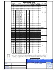
Springs<br />
Features + Application Information<br />
1. High deflection, low natural frequency<br />
2. Springs should be selected in the range of minus 30% to plus 25% of rated load (RL)<br />
3. Springs electrogalvanized in accordance with ASTM B633-13 Type II, Class 2<br />
Dimensional + Model Selection Data<br />
Spring no.<br />
021<br />
022<br />
023<br />
024<br />
041<br />
042<br />
043<br />
044<br />
045<br />
101<br />
102<br />
103<br />
104<br />
105<br />
106<br />
107<br />
108<br />
109<br />
110<br />
111<br />
112<br />
113<br />
121<br />
122<br />
123<br />
124<br />
125<br />
126<br />
127<br />
140<br />
141<br />
142<br />
143<br />
144<br />
147<br />
148A<br />
146B<br />
150<br />
151<br />
152<br />
153<br />
154<br />
155<br />
156<br />
157<br />
158<br />
159<br />
161<br />
181<br />
182<br />
183<br />
184<br />
185<br />
186<br />
187<br />
Main<br />
SILVER<br />
SILVER<br />
SILVER<br />
SILVER<br />
SILVER<br />
SILVER<br />
SILVER<br />
SILVER<br />
SILVER<br />
SILVER<br />
SILVER<br />
SILVER<br />
SILVER<br />
SILVER<br />
SILVER<br />
SILVER<br />
SILVER<br />
SILVER<br />
SILVER<br />
SILVER<br />
SILVER<br />
SILVER<br />
SILVER<br />
SILVER<br />
SILVER<br />
SILVER<br />
SILVER<br />
SILVER<br />
SILVER<br />
SILVER<br />
SILVER<br />
SILVER<br />
SILVER<br />
SILVER<br />
SILVER<br />
SILVER<br />
SILVER<br />
SILVER<br />
SILVER<br />
SILVER<br />
SILVER<br />
SILVER<br />
SILVER<br />
SILVER<br />
SILVER<br />
SILVER<br />
SILVER<br />
SILVER<br />
SILVER<br />
SILVER<br />
SILVER<br />
SILVER<br />
SILVER<br />
SILVER<br />
SILVER<br />
Color<br />
Stripe<br />
BLUE<br />
RED<br />
YELLOW<br />
WHITE<br />
BLUE<br />
RED<br />
YELLOW<br />
WHITE<br />
PINK<br />
PINK<br />
BLACK<br />
BLUE<br />
YELLOW<br />
BROWN<br />
RED<br />
PURPLE<br />
ORANGE<br />
GREEN<br />
GRAY<br />
WHITE<br />
GOLD<br />
NIL<br />
BLUE<br />
ORANGE<br />
BROWN<br />
BLACK<br />
YELLOW<br />
RED<br />
GREEN<br />
BLUE<br />
BLACK<br />
RED<br />
GREEN<br />
GRAY<br />
WHITE<br />
YELLOW<br />
WHITE<br />
BROWN<br />
ORANGE<br />
GREEN<br />
RED<br />
BLACK<br />
WHITE<br />
GRAY<br />
BLUE<br />
GOLD<br />
NIL<br />
RED<br />
PINK<br />
GREEN<br />
BLUE<br />
YELLOW<br />
BROWN<br />
RED<br />
WHITE<br />
RL<br />
(lbs)<br />
20<br />
44<br />
70<br />
100<br />
15<br />
33<br />
57<br />
76<br />
148<br />
56<br />
76<br />
113<br />
150<br />
216<br />
300<br />
400<br />
500<br />
600<br />
733<br />
866<br />
1000<br />
466<br />
40<br />
66<br />
110<br />
173<br />
246<br />
300<br />
560<br />
66<br />
133<br />
250<br />
333<br />
476<br />
953<br />
1261<br />
400<br />
83<br />
150<br />
216<br />
300<br />
400<br />
500<br />
600<br />
733<br />
1200<br />
1666<br />
416<br />
86<br />
133<br />
180<br />
266<br />
486<br />
713<br />
926<br />
GALVANIZED STEEL SPRINGS<br />
SL<br />
(lbs)<br />
Deflection at SL<br />
(inches)<br />
Spring constant<br />
(lb/inch)<br />
30<br />
0.75<br />
40<br />
66<br />
0.75<br />
88<br />
105<br />
0.75<br />
140<br />
150<br />
0.75<br />
200<br />
23<br />
1.54<br />
15<br />
50<br />
1.48<br />
34<br />
86<br />
1.39<br />
62<br />
115<br />
1.33<br />
87<br />
222<br />
1.33<br />
168<br />
85<br />
1.40<br />
61<br />
115<br />
1.30<br />
89<br />
170<br />
1.30<br />
131<br />
225<br />
1.30<br />
174<br />
325<br />
1.20<br />
271<br />
450<br />
1.20<br />
375<br />
600<br />
1.20<br />
500<br />
750<br />
1.10<br />
682<br />
900<br />
1.00<br />
900<br />
1100<br />
0.80<br />
1375<br />
1300<br />
0.80<br />
1625<br />
1500<br />
1.00<br />
1500<br />
700<br />
1.00<br />
700<br />
60<br />
1.30<br />
47<br />
100<br />
1.30<br />
77<br />
165<br />
1.20<br />
138<br />
260<br />
1.00<br />
260<br />
370<br />
0.80<br />
463<br />
450<br />
0.50<br />
900<br />
840<br />
1.15<br />
731<br />
100<br />
2.25<br />
45<br />
200<br />
2.25<br />
89<br />
375<br />
2.00<br />
188<br />
500<br />
2.00<br />
250<br />
714<br />
2.00<br />
357<br />
1430<br />
2.00<br />
715<br />
1892<br />
2.00<br />
946<br />
600<br />
2.00<br />
300<br />
125<br />
1.30<br />
97<br />
225<br />
1.30<br />
174<br />
325<br />
1.20<br />
271<br />
450<br />
1.20<br />
375<br />
600<br />
1.20<br />
500<br />
750<br />
1.10<br />
682<br />
900<br />
1.00<br />
900<br />
1100<br />
0.90<br />
1223<br />
1800<br />
1.00<br />
1800<br />
2500<br />
1.00<br />
2500<br />
625<br />
1.00<br />
625<br />
130<br />
4.30<br />
30<br />
200<br />
4.00<br />
50<br />
270<br />
3.60<br />
75<br />
400<br />
3.20<br />
125<br />
730<br />
3.60<br />
200<br />
1070<br />
3.00<br />
350<br />
1390<br />
3.00<br />
464<br />
199 SILVER BLACK 533 800<br />
3.00<br />
SL: Load at which spring will become solid or theoretical maximum load<br />
RL: Rated load based on ASHRAE defined 50% additional travel to solid<br />
FSH: Free spring height<br />
(Refer to page 2 for isolator star rating system)<br />
www.vimco.biz Due to our policy of continual product development and improvement, all specifications<br />
G-<strong>1010</strong> Rev. 2 (page 22)<br />
267<br />
are subject to change without prior notice. Please consult your local rep. for updates.<br />
O.D.<br />
1 1/4<br />
1 1/2<br />
1 1/4 2 1/4<br />
2<br />
1 5/32<br />
4<br />
2 2 3/4<br />
2<br />
1 1/4<br />
2 1/2<br />
1 5/16<br />
2 1/2<br />
1 11/16<br />
FSH<br />
5<br />
3 5/8<br />
6<br />
Rating
LIMITED WARRANTY<br />
Subject to terms and conditions herein, <strong>Vibration</strong> <strong>Management</strong> <strong>Corporation</strong> ("VIMCO") warrants to the original owner<br />
at the original installation site that products manufactured by VIMCO ("Products") comply, at the time of manufacture,<br />
with VIMCO literature, and will be free from defects in materials and workmanship for a period of 12 months after the<br />
date of start-up or 18 months after the date of shipment from factory, whichever shall be less (the "Warranty Period")<br />
REMEDY<br />
A. The sole remedy for breach of this warranty is expressly limited to either the repair / ex-factory replacement, or<br />
refund of VIMCO ex-factory sale price (at VIMCO's sole option), of any Product found to have manufacturing<br />
defects under conditions of normal use within the Warranty Period. Installation is not included.<br />
B. The owner must notify the original installer of the Product and VIMCO (Attn: Warranty Claims, 5930 Thomas Road<br />
Houston, TX 77041), in writing, within the Warranty Period, providing a detailed description of all claimed defects.<br />
Transportation to factory or other designated facility for repairs of any Products or components of Products alleged<br />
defective shall, in all events, be the responsibility and at the cost of the owner.<br />
EXCLUSIONS<br />
VIMCO shall have no liability for:<br />
A. Incidental, special or consequential damages such as loss of the use of products, facilities or production,<br />
inconvenience, loss of time or labor expense involved in repairing or replacing the alleged defective Product.<br />
B. The performance of any Product under conditions varying materially from those under which such Product is<br />
usually tested under industry standards as of the time of shipment.<br />
C. Any damage to the Product due to abrasion, erosion, corrosion, deterioration, abnormal temperatures or the<br />
influence of foreign matter or energy.<br />
D. The design or operation of owner's plant or equipment or of any facility or system of which any Product<br />
may be made a part.<br />
E. The suitability of any Product for any particular application.<br />
F. Any failure resulting from misuse, modification not authorized by VIMCO in writing, improper installation<br />
or lack of proper maintenance.<br />
G. Equipment furnished by owner, either mounted or unmounted, or when contracted for by the owner to be<br />
installed or handled.<br />
VIMCO's liability under this warranty shall not in any case exceed the VIMCO ex-factory sale price for the Product<br />
found to be defective.<br />
THIRD-PARTY WARRANTIES<br />
For goods or components not manufactured by VIMCO, above mentioned warranty obligations of VIMCO shall be limited<br />
by the warranty actually extended to VIMCO by its vendors.<br />
SEVERABILITY<br />
To the extent that any provision of this warranty would be void or prohibited under applicable law, such provisions<br />
shall be limited in effect to the minimum extent necessary to render the remaining provisions hereof enforceable.<br />
NO OTHER WARRANTIES<br />
VIMCO makes no implied warranty of merchantability or fitness for particular purpose, or other warranties with respect<br />
to any products or services except as expressly set forth in this limited warranty.<br />
www.vimco.biz G-<strong>1010</strong> Rev. 2 (page 23)
Houston - Texas 77041, USA<br />
T: +1-713-460-VIMCO +1-713-983-VIMCO<br />
T: F: +1-713-983-9933<br />
+1-713-460-1100 E: sales@vimco.biz<br />
+1-713-460-8462<br />
+1-713-983-8462<br />
A