CERTIFICATE OF APPROVAL No CF 474 PROMAT ... - Himerpa
CERTIFICATE OF APPROVAL No CF 474 PROMAT ... - Himerpa
CERTIFICATE OF APPROVAL No CF 474 PROMAT ... - Himerpa

Create successful ePaper yourself
Turn your PDF publications into a flip-book with our unique Google optimized e-Paper software.
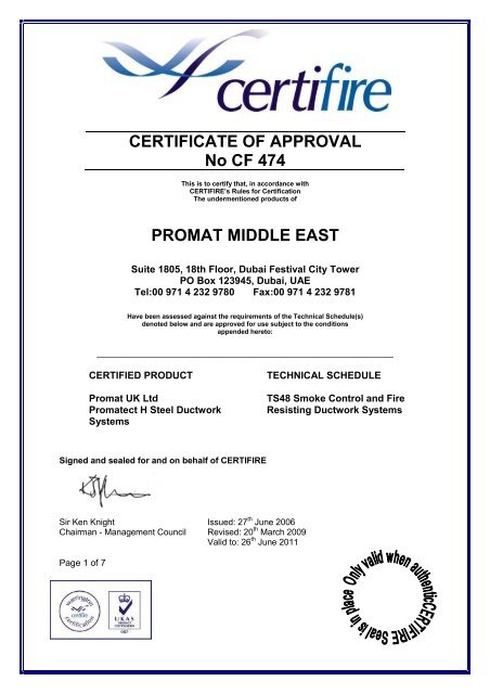
<strong>CERTIFICATE</strong> <strong>OF</strong> <strong>APPROVAL</strong><br />
<strong>No</strong> <strong>CF</strong> <strong>474</strong><br />
This is to certify that, in accordance with<br />
CERTIFIRE’s Rules for Certification<br />
The undermentioned products of<br />
<strong>PROMAT</strong> MIDDLE EAST<br />
Suite 1805, 18th Floor, Dubai Festival City Tower<br />
PO Box 123945, Dubai, UAE<br />
Tel:00 971 4 232 9780 Fax:00 971 4 232 9781<br />
Have been assessed against the requirements of the Technical Schedule(s)<br />
denoted below and are approved for use subject to the conditions<br />
appended hereto:<br />
_________________________________________________________________________________<br />
CERTIFIED PRODUCT<br />
Promat UK Ltd<br />
Promatect H Steel Ductwork<br />
Systems<br />
TECHNICAL SCHEDULE<br />
TS48 Smoke Control and Fire<br />
Resisting Ductwork Systems<br />
Signed and sealed for and on behalf of CERTIFIRE<br />
Sir Ken Knight Issued: 27 th June 2006<br />
Chairman - Management Council Revised: 20 th March 2009<br />
Valid to: 26 th June 2011<br />
Page 1 of 7
<strong>CERTIFICATE</strong> <strong>No</strong> <strong>CF</strong> <strong>474</strong><br />
<strong>PROMAT</strong> MIDDLE EAST<br />
<strong>PROMAT</strong> MIDDLE EAST – Promatect H Steel Ventilation, Smoke Outlet and<br />
Kitchen Extract Ductwork Systems<br />
1. This approval relates to the use of the above ductwork systems in providing fire<br />
resistance of up to 240 minutes stability, integrity and insulation, as defined in BS 476:<br />
Part 24: 1987 (ISO 6944: 1985). Subject to the undermentioned conditions, the ductwork<br />
systems will meet the relevant requirements of BS 5588 for fire resisting compartment<br />
ductwork systems, for periods of up to 240 minutes (dependant upon design limitations)<br />
when used in accordance with the provisions therein.<br />
2. This certification is designed to demonstrate compliance of the product or system<br />
specifically with Approved Document B (England and Wales), Section D of the Technical<br />
Standards (Scotland), Technical Booklet E (N. Ireland). If compliance is required to other<br />
regulatory or guidance documents there may be additional considerations or conflict to<br />
be taken into account.’<br />
3. The ductwork systems are approved on the basis of:<br />
i) Initial type testing<br />
ii) Audit testing at the frequency specified in TS48<br />
iii) A design appraisal against TS48<br />
iv) Certification of quality management system to ISO 9001: 2000.<br />
v) Inspection and surveillance of factory production control<br />
4. The ductwork systems comprise Promatect H board screwed to steel channel collars<br />
around a steel duct and edge fixed at the longitudinal corners, with rock wool insulation<br />
fitted to some constructions between the board and the steel duct.<br />
5. This approval is applicable to insulated and partially insulated Promatect H steel ductwork<br />
systems as described within this Certificate.<br />
6. The ductwork systems shall be mechanically supported from floor and/or wall constructions<br />
or structural steel members having a fire resistance of at least the same period as the<br />
ductwork systems.<br />
7. The approval relates to on going production. Product and/or its immediate packaging is<br />
identified with the manufacturers’ name, the product name or number, the CERTIFIRE<br />
name or name and mark, together with the CERTIFIRE certificate number and application<br />
where appropriate.<br />
Page 2 of 7 Signed<br />
Issued: 28 th June 2006<br />
Revised: 20 th March 2009<br />
Valid to: 27 th June 2011
<strong>CERTIFICATE</strong> <strong>No</strong> <strong>CF</strong> <strong>474</strong><br />
<strong>PROMAT</strong> MIDDLE EAST<br />
<strong>PROMAT</strong> MIDDLE EAST – Promatect H Steel Systems<br />
Horizontal ducts<br />
Steel duct assembly<br />
The Promatect H steel duct system consists of a steel duct protected with minimum 15mm-thick<br />
Promatect H board. The minimum construction requirements for the steel duct are as follows:<br />
Wall thickness - minimum 0.7mm-thick galvanised steel sheet (Table 1),<br />
Longitudinal seams - Pittsburgh Lock or Grooved Corner Seam,<br />
Cross joints - rolled steel angle flanged cross-joints or equivalent rollformed sheet steel<br />
profile cross-joints (Table 1),<br />
Maximum section length - 1220mm,<br />
Maximum size – 6000mm wide x 2500mm high (Table 1).<br />
Table 1 Minimum construction requirements for steel duct<br />
Maximum size of<br />
duct longer side<br />
- mm<br />
Thickness of<br />
steel sheet<br />
- mm<br />
Size of cross joint<br />
angle<br />
– mm x mmx mm<br />
Stiffening<br />
collar<br />
required<br />
Up to 800 0.7 25 x 25 x 3 <strong>No</strong><br />
Up to 1000 1.0 30 x 30 x 4 <strong>No</strong><br />
Up to 1500 1.0 30 x 30 x 4 Yes<br />
Up to 2500 1.0 40 x 40 x 4 Yes<br />
Up to 3000 1.2 50 x 50 x 5 Yes<br />
Up to 6000 1.2 70 x 70 x 6 Yes<br />
The rolled steel angles of the cross joints are welded at the corners and fastened to the duct<br />
walls with minimum 5mm-diameter steel rivets (or equivalent) at maximum 150mm centres or<br />
spot-welded at 75mm nominal centres. The cross joints of adjacent sections are fastened with<br />
steel bolts at the corners and at 300mm maximum centres along each of the four sides.<br />
The stiffening collars are required, as shown in the above table, for ducts with a section length<br />
greater than 625mm. Each collar is fitted at approximately mid-length of the duct section and is<br />
made of the same size of steel angle as used for the cross joints (or equivalent). The angles are<br />
welded or bolted together at the corners and fastened to the duct walls with minimum 5mmdiameter<br />
steel rivets (or equivalent) at maximum 300mm centres.<br />
Page 3 of 7 Signed<br />
Issued: 28 th June 2006<br />
Revised: 20 th March 2009<br />
Valid to: 27 th June 2011
<strong>CERTIFICATE</strong> <strong>No</strong> <strong>CF</strong> <strong>474</strong><br />
<strong>PROMAT</strong> MIDDLE EAST<br />
<strong>PROMAT</strong> MIDDLE EAST – Promatect H Steel Systems<br />
Hanger supports<br />
Steel hangers consisting of a pair of threaded drop rods and an angle or channel bearer under<br />
the steel duct. The maximum spacing of the hangers is 1220mm. The maximum tensile stress<br />
in the rods and the bending stress in the bearers must not exceed 10N/mm 2 for 120 minutes fire<br />
resistance and 6N/mm 2 for 240 minutes fire resistance.<br />
For steel ducts wider than 3000mm, an additional drop rod is fitted at approximately mid-width of<br />
the duct at each hanger position. The rod passes through the top wall of the duct and supports<br />
the top of the duct with steel nuts and large steel washers fitted to the threaded rod. The drop<br />
rod also passes through the bottom wall of the duct and supports the bearer of the hanger.<br />
The fixings used to fasten the threaded rod hangers to concrete soffits are all-steel expanding<br />
anchors (e.g. Hilti HKD anchors) with a penetration in the concrete of at least 50mm for 120<br />
minutes fire resistance and 60mm for 240 minutes fire resistance. The anchors must match the<br />
size of the threaded rods, be of sufficient strength to support the weight of the duct and be fitted<br />
in accordance with the manufacturer's instructions. When the hanger rods are suspended from<br />
protected structural steel beams, they must be protected for at least 300 mm from the beams<br />
with the same level of protection as the structural beams.<br />
For steel ducts wider than 3000mm, steel struts are included within the ducts at the positions of<br />
the cross-joints. The struts are positioned at 2000mm maximum centres across the width of the<br />
duct. The maximum stresses in the struts must not exceed 10N/mm 2 for 120 minutes fire<br />
resistance and 6N/mm 2 for 240 minutes fire resistance.<br />
Steel collars to support boards<br />
Steel channel collars are folded around the duct at maximum 610mm centres. The collars are<br />
steel channels, minimum 50mm flanges x 50mm web x 0.6mm thick, which are fastened together<br />
at the corners with steel rivets or self-tapping screws. The channels are not directly fastened to<br />
the duct except for ducts with dimensions greater than 1500mm wide or 1500mm high where the<br />
channels under the soffit of the duct and the channels up the sides of the duct must be fastened<br />
to either the cross joint angles or the stiffening collar angles with either steel self-tapping screws<br />
or steel rivets at 300mm nominal centres. Where the depth of the flanged cross-joints or the<br />
hanger bearer is greater than 50mm, the depth of the channel collars must be increased to suit.<br />
Similarly, where 100mm thick rock wool insulation is fitted around the steel duct the minimum<br />
size of the channel collars is 100mm flanges x 70mm web x 0.8mm thick.<br />
Page 4 of 7 Signed<br />
Issued: 28 th June 2006<br />
Revised: 20 th March 2009<br />
Valid to: 27 th June 2011
<strong>CERTIFICATE</strong> <strong>No</strong> <strong>CF</strong> <strong>474</strong><br />
<strong>PROMAT</strong> MIDDLE EAST<br />
<strong>PROMAT</strong> MIDDLE EAST – Promatect H Steel Systems<br />
Rock wool insulation<br />
Where 120 or 240 minutes insulation performance is required, rock wool insulation of 100kg/m 3<br />
density is fitted around the steel duct. The insulation is minimum 50mm thick for a 120-minute<br />
fire rating and minimum 100mm thick (fitted in at least two layers) for a 240-minute fire rating.<br />
The joints in the rock wool batts are tight butt joints and staggered between layers by at least<br />
150mm. The steel channel collars are also filled with the rock wool.<br />
Promatect H boards<br />
Promatect H boards, 15, 20 or 25mm thick, are screwed to the channel collars with M4 steel selftapping<br />
screws at 200mm nominal centres. Transverse board joints are coincident with the<br />
channels. The boards at the longitudinal corner joints are either screwed to a galvanised steel<br />
angle, minimum 25mm x 25mm x 0.6mm thick, with M4 steel self tapping screws at 200mm<br />
nominal centres or directly fastened together with steel staples, minimum 50mm long x 10mm<br />
wide x 1.5mm thick, at 150mm maximum centres.<br />
The maximum area of unsupported board is 1.5m 2 . In order to achieve this for larger duct sizes<br />
either the spacing of the channel collars is reduced or longitudinal channels (the same size as<br />
the collars) are fitted between the transverse collars. Any longitudinal board joint in the<br />
Promatect H (other than a corner joint) must be backed by a steel channel (the same size as the<br />
collars). Where the hanger drop rods pass through the Promatect H board the penetrations are<br />
sealed with Promaseal fire-rated silicone mastic or Promaseal intumescent mastic or equivalent.<br />
The thicknesses of Promatect H board and rock wool for the various fire resistance ratings are<br />
given in Table 2.<br />
Table 2 – Thickness of Promatect H board and rock wool specification<br />
Fire resistance - minutes<br />
Promatect H Rock wool<br />
Stability Integrity Insulation mm mm x kg/m 3<br />
120 120 - 9 -<br />
120 120 30 20 -<br />
120 120 60 12 50 x 60<br />
120 120 120 15 50 x 100<br />
240 240 - 12 -<br />
240 240 30 20 -<br />
240 240 240 25 100 x 100<br />
Page 5 of 7 Signed<br />
Issued: 28 th June 2006<br />
Revised: 20 th March 2009<br />
Valid to: 27 th June 2011
<strong>CERTIFICATE</strong> <strong>No</strong> <strong>CF</strong> <strong>474</strong><br />
<strong>PROMAT</strong> MIDDLE EAST<br />
<strong>PROMAT</strong> MIDDLE EAST – Promatect H Steel Systems<br />
Penetration details<br />
At wall penetrations, L-shaped collars of Promatect H, made of strips at least 150mm wide x the<br />
same thickness as the casing screwed together at 200mm nominal centres, are fitted around the<br />
duct on both sides of the wall. (For 9mm and 12mm thick Promatect H the boards are fastened<br />
together with a steel angle minimum 25mm x 25mm x 0.6mm thick). They are fastened to the<br />
Promatect H casing of the duct with steel screws at 200mm maximum centres. The space<br />
between the Promatect H casing and the reveals of the opening is filled with rock wool of<br />
minimum density 100kg/m 3 . The collar is not fastened to the wall but is fitted against the wall<br />
with Promaseal fire rated acrylic / silicone sealant. A steel duct cross joint or stiffening collar is<br />
located at compartment wall penetrations.<br />
One, two and three sided ducts<br />
One, two and three-sided Promatect H steel ducts are constructed using the adjacent<br />
concrete/masonry walls and floor slab to support the assembly. The surrounding building<br />
elements must have a fire resistance equal to or higher than the fire resistance required for the<br />
duct. The 4-sided steel duct and hanger supports are as described above.<br />
The steel channels are fitted around one, two or three sides of the steel duct, in a similar way to<br />
the 4-sided system, except that the ends of the channels are fixed to minimum 40mm x 40mm x<br />
1.5mm angles anchored to the wall or floor elements with minimum M8 all-steel expanding<br />
anchor bolts at 400mm maximum centres. A bead of Promaseal fire rated acrylic / silicone<br />
sealant is fitted between the angles and the wall or floor. The channels are fastened to the<br />
angles with minimum two M4 steel self-tapping screws or M4 steel rivets at each junction. The<br />
size and spacing of the screws and anchors must be adjusted depending on the weight of the<br />
duct assembly. The maximum bearing, tensile and shear stresses for the steel angles, screws<br />
and anchors is 10N/mm 2 for a fire exposure of 120 minutes and 6N/mm 2 for a fire exposure of<br />
240 minutes.<br />
For steel ducts over 1220mm wide the channels under the soffit of the duct are fastened to either<br />
the cross joint angles or the stiffening collar angles as for the 4-sided duct. The maximum size of<br />
steel duct is 6000mm wide x 2500mm high.<br />
The Promatect H boards are fastened to the channels and angles in the same way as for the 4-<br />
sided duct system. The penetration seal system is the same as for the 4-sided duct system.<br />
Page 6 of 7 Signed<br />
Issued: 28 th June 2006<br />
Revised: 20 th March 2009<br />
Valid to: 27 th June 2011
<strong>CERTIFICATE</strong> <strong>No</strong> <strong>CF</strong> <strong>474</strong><br />
<strong>PROMAT</strong> MIDDLE EAST<br />
<strong>PROMAT</strong> MIDDLE EAST – Promatect H Steel Systems<br />
Vertical ducts<br />
The construction of vertical ducts is the same as for the horizontal ducts. In order to support the duct<br />
system in the vertical orientation, steel sections are fastened to the steel duct, either along the two<br />
longer sides or on all four sides. The weight must be taken by the steel duct and not by the Promatect<br />
H board. The steel sections either span across the opening in the concrete floor or form part of a<br />
cantilever bracket that is fastened to the building structure. If the distance between the floors is greater<br />
than 5m then intermediate supports must be fitted, e.g. cantilever bracket from adjacent fire rated wall.<br />
Also, to prevent buckling of the duct, the distance between supports must not exceed 8 times the<br />
smallest lateral dimension across the outside face of the steel duct. The weight of the duct system is<br />
taken by the building structure at each floor level. The stress limit within the steel supports is 10N/mm 2<br />
for fire exposures of up to 120 minutes and 6N/mm 2 for fire resistance periods up to 240 minutes.<br />
The design of the penetration seal for vertical ducts through concrete floors is the same as for<br />
horizontal ducts through masonry/concrete walls.<br />
Smoke outlet ducts<br />
The ducts may be used as smoke outlet ducts.<br />
Kitchen extract ducts<br />
Where the duct system is to be used as a kitchen extract duct the internal duct surface of duct type A<br />
should not exceed 140 o C mean or 180 o C maximum. The steel of the duct is deemed to be noncombustible.<br />
The thicknesses of Promatect H board and rock wool for the various fire resistance<br />
ratings are given in Table 3.<br />
Table 3 – Thickness of Promatect H board and rock wool specification for kitchen extract<br />
ducts<br />
Fire resistance - minutes<br />
Promatect H Rock wool<br />
Stability Integrity Insulation mm mm x kg/m 3<br />
120 120 30 15 50 x 100<br />
120 120 60 15 100 x 100<br />
120 120 120 15 90 x 165<br />
Table 4 Maximum loads for drop rods<br />
<strong>No</strong>minal rod Tensile stress<br />
Load<br />
diameter area kN – 2hr kg – 2hr kN – 4hr kg – 4hr<br />
mm mm 2 (BS 4190) (10N/mm 2 ) (6N/mm 2 )<br />
6 20.1 0.20 20.49 0.12 12.29<br />
8 36.6 0.37 37.31 0.22 22.39<br />
10 58.0 0.58 59.12 0.35 35.47<br />
12 84.3 0.84 85.93 0.51 51.56<br />
16 157.0 1.57 160.04 0.94 96.02<br />
20 245.0 2.45 249.75 1.47 149.85<br />
Page 7 of 7 Signed<br />
Issued: 28 th June 2006<br />
Revised: 20 th March 2009<br />
Valid to: 27 th June 2011