Competitive chiller concept with water as refrigerant
Competitive chiller concept with water as refrigerant
Competitive chiller concept with water as refrigerant

You also want an ePaper? Increase the reach of your titles
YUMPU automatically turns print PDFs into web optimized ePapers that Google loves.
DTI h<strong>as</strong> used the full software package from ConceptsNREC consisting of the 1-D meanline code called AXIAL,<br />
the 3-D geometry generation etc. code AxCent <strong>with</strong> the integrated CFD solver called PushButton. The AXIAL<br />
1-D code offers the two loss models by Koch & Smith and Wright & Miller, respectively, (12), (13), (14) but also<br />
a very flexible system that allows the calibration of almost every parameter and loss coefficients. This feature<br />
w<strong>as</strong> necessary in our c<strong>as</strong>e <strong>as</strong> the low pressure and thus low Reynolds numbers in combination <strong>with</strong> the relative<br />
Mach numbers in question required special corrections and a special calibration of the code b<strong>as</strong>ed on the me<strong>as</strong>ured<br />
performance.<br />
The design ph<strong>as</strong>e is further complicated by the fact that an axial compressor h<strong>as</strong> many variables that are of<br />
importance to both the aerodynamic and the mechanical design such <strong>as</strong> number of stages, rotational speed,<br />
diameter, blade count, blade type of profile, blade height/length ratio, thrust area at front and exit, blade<br />
angle, blade camber, leading edge and trailing edge thickness, tip clearance, etc. Identification and selection of<br />
these variables affect the compressor total pressure ratio, efficiency, relative Mach number, various types<br />
of losses, etc.<br />
The detailed 3-D design of each individual blade row followed the 1-D optimization and in particular the comprehensive<br />
CFD runs take up most of the design efforts and are rather time consuming. Figure 5 shows an<br />
example of the result of a CFD run that illustrates the flow field in one of the downstream stages, still in the<br />
transonic regime. The CFD solver could be used for multistage analysis <strong>as</strong> well, including the frozen-rotor option<br />
and various stage-stage mixing schemes.<br />
Figure 5<br />
An example of the detailed CDF calculations that were performed for each<br />
blade row in the geometry optimization process.<br />
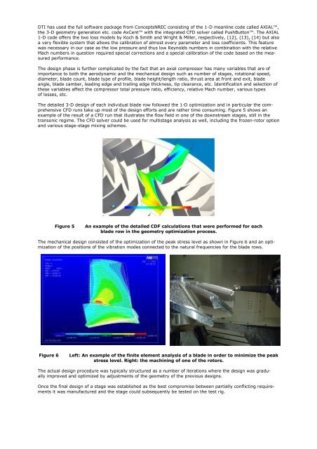
The mechanical design consisted of the optimization of the peak stress level <strong>as</strong> shown in Figure 6 and an optimization<br />
of the positions of the vibration modes connected to the natural frequencies for the blade rows.<br />
Figure 6<br />
Left: An example of the finite element analysis of a blade in order to minimize the peak<br />
stress level. Right: the machining of one of the rotors.<br />
The actual design procedure w<strong>as</strong> typically structured <strong>as</strong> a number of iterations where the design w<strong>as</strong> gradually<br />
improved and optimized by adjustments of the geometry of the previous designs.<br />
Once the final design of a stage w<strong>as</strong> established <strong>as</strong> the best compromise between partially conflicting requirements<br />
it w<strong>as</strong> manufactured and the stage could subsequently be tested on the test rig.