Competitive chiller concept with water as refrigerant
Competitive chiller concept with water as refrigerant
Competitive chiller concept with water as refrigerant

Create successful ePaper yourself
Turn your PDF publications into a flip-book with our unique Google optimized e-Paper software.
<strong>Competitive</strong> <strong>chiller</strong> <strong>concept</strong> <strong>with</strong> <strong>water</strong> <strong>as</strong> <strong>refrigerant</strong><br />
MADSBØLL H.<br />
Danish Technological Institute, Centre for Refrigeration and Heat Pump Technology,<br />
Kongsvang Allé 29, 8000 Aarhus C, Denmark<br />
hm@teknologisk.dk<br />
ABSTRACT<br />
A new type of compact, low cost and highly efficient axial compressor for <strong>water</strong> vapor h<strong>as</strong> been developed <strong>as</strong> a<br />
result of more than six years of research. The new compressor allows the design and development of competitive,<br />
large <strong>chiller</strong>s b<strong>as</strong>ed on <strong>water</strong> <strong>as</strong> <strong>refrigerant</strong> <strong>as</strong> an alternative to the traditional <strong>refrigerant</strong>s (HFC’s, ammonia,<br />
etc.). The design and testing of the compressor and the direct type heat-exchangers h<strong>as</strong> been performed<br />
at Danish Technological Institute. B<strong>as</strong>ed on the fundamental results, a prototype commercial <strong>chiller</strong> h<strong>as</strong> been<br />
designed, established and tested by Kobe Steel who h<strong>as</strong> the production rights along <strong>with</strong> Johnson Controls<br />
Denmark.<br />
1. INTRODUCTION<br />
The world of refrigeration is dominated by the vapor compression cycle, but the choice of media or <strong>refrigerant</strong><br />
is a pending issue. The CFC’s were banned due to the ozone depleting potential, the HFC’s may be ph<strong>as</strong>ed out<br />
due to high global warming potential, and in parallel other natural alternatives such <strong>as</strong> ammonia, carbon dioxide,<br />
hydrocarbons etc. have been applied. From numerous perspectives, <strong>water</strong> is the ultimate choice of <strong>refrigerant</strong>.<br />
It is cheap and readily available; there is no contribution to global warming, no contribution to ozone<br />
depletion. It is non-flammable and non-toxic and there are no harmful atmospheric or fire breakdown products.<br />
Water <strong>as</strong> <strong>refrigerant</strong> h<strong>as</strong> been suggested in the p<strong>as</strong>t by various authors and technical groups, and a few fullscale<br />
plants have been established (1),(2),(3). Some of them have been b<strong>as</strong>ed on the centrifugal compressors<br />
from IDE Technologies, Israel, <strong>with</strong> flexible blades <strong>as</strong> described for instance in (4). This technology h<strong>as</strong> been<br />
further developed by ILK <strong>as</strong> described in (3) and a new generation of commercial <strong>chiller</strong>s h<strong>as</strong> been announced<br />
to be marketed in 2011 (5). The use of condensing wave rotors h<strong>as</strong> been described (6) <strong>as</strong> a method that could<br />
potentially improve the performance of the vapor cycle. Vacuum ice production and snow making h<strong>as</strong> been the<br />
focus of IDE where units have been established in South Africa, Switzerland and in Japan, among others. An<br />
axial compressor type h<strong>as</strong> also been suggested for vacuum ice applications (7) and (8). Small-sized units have<br />
been suggested for instance in (9), (15) and theoretical surveys of <strong>water</strong> <strong>as</strong> <strong>refrigerant</strong> <strong>with</strong> various conclusions<br />
have also been conducted (10), (11).<br />
But the research and development work described in the present paper is the first time an axial compressor h<strong>as</strong><br />
been developed from scratch, specially designed for the application <strong>as</strong> <strong>chiller</strong> for industrial refrigeration and air<br />
condition, and <strong>with</strong> the potential for a commercial breakthrough for <strong>water</strong> <strong>as</strong> <strong>refrigerant</strong>.<br />
2. FEASIBILITY STUDY<br />
The obvious environmental advantages from using <strong>water</strong> <strong>as</strong> <strong>refrigerant</strong> were the background of a fe<strong>as</strong>ibility<br />
study that w<strong>as</strong> completed in 1996 – 98 by the former Sabroe in collaboration <strong>with</strong> Danish Technological<br />
Institute and ConceptsNREC. The objective w<strong>as</strong> to investigate whether it w<strong>as</strong> technically possible to develop a<br />
<strong>chiller</strong> for the large capacity ranges from approximately 500 kW and upwards that could be competitive compared<br />
<strong>with</strong> traditional HFC and NH 3 plants on main parameters such <strong>as</strong>:<br />
• Size (specifically the area or footprint to be used and the ability to ship in containers)<br />
• Efficiency (it should at le<strong>as</strong>t be possible to achieve the same COP <strong>as</strong> <strong>with</strong> existing technologies)<br />
• Price (sales price should match existing facilities, perhaps by including <strong>refrigerant</strong> cost, energy<br />
saving, safety equipment, etc.)<br />
The so-called LEGO plant, (2), a prototype unit b<strong>as</strong>ed on <strong>water</strong> <strong>as</strong> <strong>refrigerant</strong>, w<strong>as</strong> established prior to the<br />
fe<strong>as</strong>ibility study, and it w<strong>as</strong> in operation during the period 1995 – 2005. The LEGO plant demonstrated some of<br />
the system solutions while giving valuable operational experience. But the plant also showed that the applied<br />
generation of compressors from IDE, Israel, resulted in the plant becoming too bulky, too expensive and had<br />
too poor compressor efficiency to be commercially competitive. As a consequence, the fe<strong>as</strong>ibility study tried to<br />
identify and analyze alternative compressor solutions and the possibilities to reduce the physical dimensions<br />
and the total cost of the plant.<br />
The physical properties of <strong>water</strong> cause the technology for the plants using <strong>water</strong> <strong>as</strong> <strong>refrigerant</strong> to be somewhat<br />
different from conventional plants. There are some very specific requirements and working conditions both for
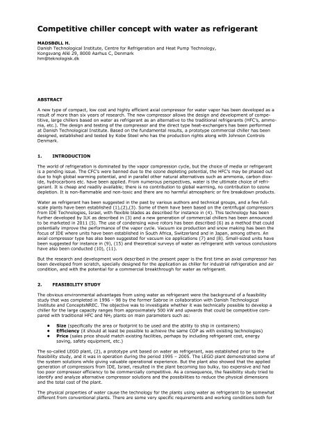
the plants and for the compressor. The vapor pressure of <strong>water</strong> is relatively low and for all temperatures below<br />
100°C it is lower than atmospheric pressure, i.e. the process runs in vacuum conditions for the temperature<br />
ranges typical for <strong>chiller</strong> operation.<br />
Figure 1 shows that the vapor pressure at a typical <strong>chiller</strong> temperature of 6-7°C is approximately 10 mbar<br />
absolute pressure while the pressure at typical condensation temperatures 25 -35°C ranges from approx. 30 to<br />
60 mbar absolute pressure. Because of the very low pressure the specific volume for <strong>water</strong> vapor is very large<br />
<strong>as</strong> shown in Figure 1.<br />
Figure 1<br />
Left: Saturation pressure for <strong>water</strong> <strong>as</strong> a function of temperature,<br />
Right: Specific volume of <strong>water</strong> vapor.<br />
Figure 2 Various types of turbo compressors were evaluated in collaboration <strong>with</strong><br />
ConceptsNREC, USA. The choice fell on the multistage axial compressor type (bottom<br />
right) <strong>as</strong> the most promising candidate - all things considered.<br />
At typical <strong>chiller</strong> temperatures (6-7°C), the specific volume is in the order of 130 to 140 m 3 /kg and <strong>as</strong> the<br />
latent heat for <strong>water</strong> is about 2.4 MJ/kg it means that an approx. 2 MW plant - which the fe<strong>as</strong>ibility study w<strong>as</strong><br />
b<strong>as</strong>ed on - must have a compressor volume flow of approx. 100 m 3 /s. Such conditions restrict the range of<br />
potential types of compressors to the relatively large turbo compressors, and a variety of candidates <strong>as</strong> shown<br />
in Figure 2 were examined on a number of parameters including production methods, material selection,<br />
flexibility etc., in addition to the mentioned three main parameters.<br />
The conclusion of the fe<strong>as</strong>ibility study w<strong>as</strong> positive; there w<strong>as</strong> a chance to develop a system that could be<br />
competitive on all three parameters – size, cost and COP – by selecting the <strong>concept</strong>:<br />
• The development of the axial compressor type <strong>as</strong> shown in figure 2, bottom right, in a special cost<br />
effective way.<br />
• In combination <strong>with</strong> an optimized version of the direct contact heat exchangers.<br />
In this way, the systems b<strong>as</strong>ed on <strong>water</strong> <strong>as</strong> media (sketched in Figure 3) would be able to compete <strong>with</strong><br />
traditional plants b<strong>as</strong>ed on NH 3 or the synthetic HCF <strong>refrigerant</strong>s on entirely commercial b<strong>as</strong>is. The sketch<br />
shows the approximate operational conditions for the unit, the developed compressor offers sufficient margin to<br />
be able to operate on a global scale of applications.
Figure 3<br />
Sketch of refrigeration system principle <strong>with</strong> direct contact heat exchangers and axial<br />
compressor. Operational conditions are indicated.<br />
However, in 2001 York Refrigeration (former Sabroe) decided to stop the project, despite the very promising<br />
prospects. At the time, the b<strong>as</strong>ic conditions had been tested either in scaled tests or in full-scale tests and a<br />
partially completed test unit w<strong>as</strong> manufactured.<br />
At the instigation of Danish Technological Institute, the project w<strong>as</strong> restarted three years later <strong>with</strong> the<br />
Japanese company Kobe Steel Ltd. (Kobelco) <strong>as</strong> industrial partner in collaboration <strong>with</strong> the following four<br />
Japanese companies: The Tokyo Electric Power Company, Incorporated, Chubu Electric Power Company,<br />
Incorporated, The Kansai Electric Power Company, Incorporated and Central Research Institute of Electric<br />
Power Industry. Subsequently, the former York Refrigeration participated <strong>as</strong> a ‘sleeping partner’ and <strong>as</strong> part of<br />
the agreement the test rig w<strong>as</strong> moved to Danish Technological Institute where continued development<br />
and testing took place.<br />
3. DESIGN AND DEVELOPMENT OF THE AXIAL COMPRESSORS<br />
The new project group comprising the new organization then restarted the development work where it had<br />
been stopped and the Danish Energy Agency (DEA) maintained to support the project <strong>as</strong> they had earlier. The<br />
central component w<strong>as</strong> the compressor, and most efforts were employed during the 6-7 years of development<br />
of design and testing the compressors at various stages of development in different versions and under various<br />
operating conditions.<br />
The principle of the compressor is b<strong>as</strong>ically the same <strong>as</strong> for all other turbo compressors. It consists of a f<strong>as</strong>t<br />
rotating component (rotor) which transfers velocity to the g<strong>as</strong> (<strong>water</strong> vapor or steam in this c<strong>as</strong>e) and a subsequent<br />
stationary part (stators) that slows down the g<strong>as</strong> and converts the velocity to pressure. The compressor<br />
principle is shown in Figure 4, and the total required pressure ratio for the compressor is achieved by adding<br />
more stages directly after each other on the same shaft and thus <strong>with</strong> the same rotational speed.<br />
Figure 4<br />
The principle of an axial compressor stage is that the rotors give the vapor high velocity<br />
and hence dynamic pressure after which the stationary stator blades again slow the<br />
vapor and convert velocity to pressure. [Wikipedia and AXIAL]<br />
The design of axial compressors is a highly specialized t<strong>as</strong>k <strong>with</strong> very high requirements to the computational<br />
tools and calculation accuracy <strong>as</strong> well <strong>as</strong> to the technical are<strong>as</strong> of expertise. At the same time, independent<br />
technical are<strong>as</strong> such <strong>as</strong> compressor aerodynamic optimization, selection of material and production method,<br />
optimization of stress level and natural frequencies, rotor dynamics and bearing specifications must be<br />
reconciled.
DTI h<strong>as</strong> used the full software package from ConceptsNREC consisting of the 1-D meanline code called AXIAL,<br />
the 3-D geometry generation etc. code AxCent <strong>with</strong> the integrated CFD solver called PushButton. The AXIAL<br />
1-D code offers the two loss models by Koch & Smith and Wright & Miller, respectively, (12), (13), (14) but also<br />
a very flexible system that allows the calibration of almost every parameter and loss coefficients. This feature<br />
w<strong>as</strong> necessary in our c<strong>as</strong>e <strong>as</strong> the low pressure and thus low Reynolds numbers in combination <strong>with</strong> the relative<br />
Mach numbers in question required special corrections and a special calibration of the code b<strong>as</strong>ed on the me<strong>as</strong>ured<br />
performance.<br />
The design ph<strong>as</strong>e is further complicated by the fact that an axial compressor h<strong>as</strong> many variables that are of<br />
importance to both the aerodynamic and the mechanical design such <strong>as</strong> number of stages, rotational speed,<br />
diameter, blade count, blade type of profile, blade height/length ratio, thrust area at front and exit, blade<br />
angle, blade camber, leading edge and trailing edge thickness, tip clearance, etc. Identification and selection of<br />
these variables affect the compressor total pressure ratio, efficiency, relative Mach number, various types<br />
of losses, etc.<br />
The detailed 3-D design of each individual blade row followed the 1-D optimization and in particular the comprehensive<br />
CFD runs take up most of the design efforts and are rather time consuming. Figure 5 shows an<br />
example of the result of a CFD run that illustrates the flow field in one of the downstream stages, still in the<br />
transonic regime. The CFD solver could be used for multistage analysis <strong>as</strong> well, including the frozen-rotor option<br />
and various stage-stage mixing schemes.<br />
Figure 5<br />
An example of the detailed CDF calculations that were performed for each<br />
blade row in the geometry optimization process.<br />
The mechanical design consisted of the optimization of the peak stress level <strong>as</strong> shown in Figure 6 and an optimization<br />
of the positions of the vibration modes connected to the natural frequencies for the blade rows.<br />
Figure 6<br />
Left: An example of the finite element analysis of a blade in order to minimize the peak<br />
stress level. Right: the machining of one of the rotors.<br />
The actual design procedure w<strong>as</strong> typically structured <strong>as</strong> a number of iterations where the design w<strong>as</strong> gradually<br />
improved and optimized by adjustments of the geometry of the previous designs.<br />
Once the final design of a stage w<strong>as</strong> established <strong>as</strong> the best compromise between partially conflicting requirements<br />
it w<strong>as</strong> manufactured and the stage could subsequently be tested on the test rig.
The project developed two compressor sizes, the largest having the capacity of approximately 100 m 3 /s corresponding<br />
to a <strong>chiller</strong> capacity of approximately 1.8 MW at 7°C. The smallest compressor h<strong>as</strong> a volume flow of<br />
approximately 40 m 3 /s, corresponding to approximately 800 kW cooling capacity.<br />
4. TEST OF COMPRESSOR AND CHILLER<br />
Figure 7<br />
Outline of rig for the <strong>water</strong> vapor compressor <strong>with</strong> the NH 3 <strong>chiller</strong> acting <strong>as</strong> load.<br />
During the test of the newly developed compressors, it w<strong>as</strong> necessary to have a rig <strong>with</strong> a cooling load of<br />
approximately 2 MW available and to be able to adjust the capacity, the evaporator and the condenser temperatures<br />
<strong>as</strong> needed. Therefore, a matching NH 3 <strong>chiller</strong> w<strong>as</strong> installed so the NH 3 <strong>chiller</strong> evaporator w<strong>as</strong> connected<br />
to the H 2O system's condenser and vice versa. All the necessary operating conditions for test of the<br />
H 2O system could be established relatively quickly. In addition, a number of by-p<strong>as</strong>s valves were arranged<br />
to help adjust the operating conditions. The entire test rig<br />
is outlined in Figure 7. The cooling towers removed the<br />
excess heat from the motors.<br />
Figure 8 The location of proximity<br />
sensors in order to monitor bearing<br />
performance.<br />
The compressor performance w<strong>as</strong> me<strong>as</strong>ured by a large<br />
number of pressure and temperature sensors inside the<br />
compressor and they were compared <strong>with</strong> the detailed<br />
three-dimensional CFD flow calculations and the 1-D<br />
mean-line predictions. Such me<strong>as</strong>urements were made for<br />
each complete <strong>as</strong>sembly of the compressor <strong>with</strong> the actual<br />
number of stages. The me<strong>as</strong>urements were also used to<br />
calibrate the software tools for better design and better<br />
prediction of the performance of the next stages.<br />
The compressor w<strong>as</strong> equipped <strong>with</strong> proximity sensors at<br />
the shaft to investigate the rotor dynamics of the system<br />
and to record data for the <strong>water</strong>-lubricated bearings, <strong>as</strong><br />
well <strong>as</strong> vibration on the compressor c<strong>as</strong>ing. The me<strong>as</strong>urements<br />
show that the overall vibration level is low, in the<br />
very best cl<strong>as</strong>s for the type and size of compressors.<br />
The performance of the evaporator h<strong>as</strong> also been me<strong>as</strong>ured<br />
and in general the value of the leaving temperature difference is less than one degree at <strong>chiller</strong> conditions.<br />
Special caution h<strong>as</strong> been shown to the design of the effective drop separation system that minimizes the<br />
carry-over from the fl<strong>as</strong>h evaporator.
Figure 9 To the left it appears how the pressure and temperature me<strong>as</strong>urements of the<br />
compressor performance were made primarily by sensors in the compressor house and<br />
partly by a robot on top. To the right it appears how vacuum is maintained by means of<br />
a Roots pump and a rotary vane pump.<br />
Similarly, the losses in the condenser have been me<strong>as</strong>ured, and in general the leaving temperature difference<br />
at design conditions is less than one degree, including the contribution from the non-condensable g<strong>as</strong>ses. The<br />
cooling <strong>water</strong> to the condenser is circulated through the cooling towers and will therefore inherently contain<br />
some air to be continuously removed at the vacuum conditions. That takes place in a specially designed twostage<br />
deaerator system integrated into the condenser.<br />
The system is very efficient and imposes a loss of only 1-2% of the total energy consumption where competing<br />
systems typically have losses in the range 5-10%. The vacuum system is shown in Figure 9 and consists of a<br />
Roots pump to the low pressure level <strong>with</strong> a rotary vane vacuum pump on top at the higher pressure level to<br />
take the non-condensable g<strong>as</strong>es to atmospheric pressure. Due to various tests the piping shown in the figure<br />
on the test rig is somewhat more complicated than it will be in the upcoming commercial version.<br />
5. EXPECTED PERFORMANCE AND CHILLER DATA<br />
Capacity: As mentioned, two compressor sizes were provisionally developed which in turn corresponds to two<br />
different capacities. The physical properties of <strong>water</strong> make the capacity vary <strong>as</strong> a function of the outlet temperature<br />
by almost 10% per degree, which is a somewhat stronger dependency than applicable to the traditional<br />
<strong>refrigerant</strong>s. Figure 10 shows how the capacity varies <strong>as</strong> a function of the outlet <strong>chiller</strong> temperature.<br />
Physical size: The units will be approximately <strong>as</strong> compact <strong>as</strong> the traditional NH 3 and HFC systems and thus<br />
significantly smaller than the previous LEGO system. The final dimensions are not determined yet, but for the<br />
approx. 1800 kW unit, the length, width and height will be approximately 4.5 x 2.5 x 2.3 m and the smaller<br />
approximately 800 kW unit, the dimensions will be approximately 3 x 1.7 x 2.3m.<br />
One drawback of the <strong>chiller</strong> units is the need for some inflow height to <strong>water</strong> pumps (NPSH value), typically 1.2<br />
– 1.5 m due to the vacuum conditions in the evaporator and condenser which calls for the possibility to install<br />
pumps in the b<strong>as</strong>ement, alternatively submerged or alternatively the plant h<strong>as</strong> to be raised.<br />
EER: In the U.S., <strong>chiller</strong>s for air conditioning are specified according to both design point EER (COP) and more<br />
informative according to the partial load ratio, defined <strong>as</strong> the weighted average value of EER at four welldefined<br />
operating points. The European Eurovent standard h<strong>as</strong> taken up the method and defined conditions<br />
b<strong>as</strong>ed on the average European climatic conditions, <strong>as</strong> shown in the table below.
3000<br />
Cooling capacity [kW]<br />
2500<br />
2000<br />
1500<br />
1000<br />
500<br />
Large<br />
Small<br />
0<br />
0 5 10 15<br />
Chiller <strong>water</strong> temperature [C]<br />
Figure 10<br />
Cooling capacity of the <strong>chiller</strong> <strong>as</strong> a function of the outlet temperature of the cold <strong>water</strong>.<br />
Table 1 EER values b<strong>as</strong>ed on test rig data.<br />
Load conditions<br />
Eurovent - ESEER (Europa)<br />
(12/7C) cold <strong>water</strong><br />
ARI 550/590 - IPLV (USA)<br />
(54/44F – 12,2/6,7C)<br />
Condenser cooling <strong>water</strong><br />
inlet temperature ( C )<br />
Relative<br />
weight (%)<br />
Condenser cooling <strong>water</strong><br />
inlet temperature ( C )<br />
Relative<br />
weight (%)<br />
100% load 30.0 3 29.4 1<br />
75% load 26.0 33 23.9 42<br />
50% load 22.0 41 18.3 45<br />
25% load 18.0 23 18.3 12<br />
EER 6.00 EER 6.05<br />
ESEER part load 8.62 IPLV part load 9.50<br />
The condenser <strong>water</strong> flow is defined in the European standard to be set to the value where the heating is 5.0°C<br />
in the condenser at full load; that is, heating from 30°C inlet condenser temperature to 35°C outlet<br />
temperature.<br />
In the U.S. standard, the heating is set to be approx. 5.2°C, i.e. the outlet temperature of approx. 34.6 °C. In<br />
all c<strong>as</strong>es, the calculations have been performed <strong>with</strong> the <strong>as</strong>sumed electrical efficiency for the motor of 95% and<br />
all auxiliary equipment h<strong>as</strong> been included.<br />
For typical Danish conditions <strong>with</strong> the temperature conditions 27/22°C and 12/7°C, the EER is expected to be<br />
approximately 8.4 at full load.<br />
Finally it can be mentioned that due to the high discharge g<strong>as</strong> temperature of more than 200°C the <strong>chiller</strong> may<br />
be fitted <strong>with</strong> a 100 - 200 kW hot-<strong>water</strong> system. If there is a need for clean <strong>water</strong>, the large capacity <strong>chiller</strong> can<br />
produce approx. 3 m 3 /h of distilled <strong>water</strong> <strong>as</strong> a by-product during the normal process of cooling by applying the<br />
indirect condenser.<br />
6. PERSPECTIVES<br />
The production rights of the developed compressors and the developed direct contact heat exchangers and<br />
<strong>chiller</strong> systems are shared between Kobe Steel Ltd (Kobelco) and Johnson Controls Denmark. Before the<br />
market introduction a commercialization ph<strong>as</strong>e will be needed <strong>as</strong> well <strong>as</strong> various long-term tests. Therefore, it<br />
can be expected to take 2-4 years before the plants are ready for introduction on the market, depending on<br />
size and version of the <strong>chiller</strong>.<br />
A prototype of the Japanese commercial version - that h<strong>as</strong> to meet some specific Japanese requirements - h<strong>as</strong><br />
been running various tests over the p<strong>as</strong>t year in Japan, including tests of specially developed indirect type of<br />
heat exchangers. An actual commercial version is under design by Kobe Steel for optimization of production and<br />
for long-term tests in Japan.<br />
Work is underway to establish two demonstration units in Denmark. It will be a global version – that is, for<br />
global weather conditions - <strong>with</strong> direct contact heat exchangers and for an industrial cooling application <strong>as</strong> well<br />
<strong>as</strong> for air-condition application, also for product maturing, long-term tests and <strong>as</strong> a showc<strong>as</strong>e. It is expected<br />
that the two units will be in operation <strong>with</strong>in approximately two years.
It is one of the great advantages of the developed compressor and heat exchanger technology that it - <strong>with</strong><br />
smaller modifications – can be designed and manufactured in many different varieties for different purposes.<br />
Possible future applications could for instance be:<br />
- high temperature heat pumps<br />
- more energy efficient systems for drying and concentration t<strong>as</strong>ks <strong>with</strong> recompression of <strong>water</strong> vapor<br />
(VRC)<br />
- ice production for cold storage for peak cooling demand<br />
- ice production to take advantage of low prices during off-peak periods in the electricity supply.<br />
Figure 11<br />
Left: Test rig <strong>with</strong> the larger 1.8 MW compressor. The commercial version is<br />
expected to have similar appearance, <strong>with</strong>out all the instrumentation. Right: The<br />
smaller 800 kW compressor.<br />
7. REFERENCE LIST<br />
(1) Andersen K., Boldvig F. 1986. Large capacity Heat Pump using Vacuum Ice Production <strong>as</strong> Heat<br />
Source. Proc XVIIth International Conf of Refrigeration, Vienna. 1986, s. 694-701.<br />
(2) Madsboll H, Minds G. 1996. A 2 MW Industrial Chiller using Water <strong>as</strong> Refrigerant. Proc IIR Conf<br />
Applicaitons of Natural Refrigerants, Aarhus. 1996, s. 567-576.<br />
(3) Albring P., Heinrich G. 1998. Turbo Chiller <strong>with</strong> Water <strong>as</strong> Refrigerant. Proc IIR Conf Natural<br />
Working Fluids, Oslo. 1998, s. 93-103.<br />
(4) Koren A., Ophir A. 1996. Water vapor technology. Proc IIR Conf Applications for Natural<br />
Refrigerants Aarhus . Sept 1996, s. 559-565.<br />
(5) Albring, P. 2008. R718 W<strong>as</strong>ser als Kältemittel 3. Generation. ILK homepage -<br />
http://www.ilkdresden.de : s.n., 06 2008.<br />
(6) Kharazi A., Akbari P, Müller N,. 2005. Preliminary Study of Novel R718 Compression<br />
Refrigeration Cycle Using a Three-Port Condensing Wave Rotor. ASME Journal of Engineering for<br />
G<strong>as</strong> Turbines and Power. July 2005, s. 539-544.<br />
(7) Paul, J. 1996. Non-conventional Cooling Systems for Mines. Proc FRIGAIR, Johannesburg. March<br />
1996.<br />
(8) Paul, J. 2007. State-Of-The-Art for Cooling <strong>with</strong> Water <strong>as</strong> Refrigerant (R718). Proc IIR Conf of<br />
Refrigeration, Beijing. 2007, s. ICR07-B2-856.<br />
(9) Lennie, Malcolm. 2010. Company profile Aqu<strong>as</strong>tar. [Online] 2010. www.aqu<strong>as</strong>tarcooling.com.<br />
(10) Wight, S.E., Tsuk<strong>as</strong>a, Y., Le Drew, D'Orsi, N.C. 2000. The Efficiency Limits of Water Vapor<br />
Compressors. s.l. : ConceptsETI Final Report, 2000.<br />
(11) Lachner, B.F. 2004. The Use of Water <strong>as</strong> a Refrigerant: Impact on Cycle Modifications on<br />
Commercial Fe<strong>as</strong>ibility. s.l. : University of Wisconsin - Madison, 2004.<br />
(12) Koch, C og Smith, L. 1976. Loss Sources and Magnitudes in Axial-Flow Compressors. ASME<br />
Journal of Engineering for Power, Vol 98. 1976, s. 411-424.<br />
(13) An improved compressor performance model. Wright P.I., Miller D.C. 1991. 1991, IMechE paper,<br />
s. C423/028.<br />
(14) Off-design prediction of compressor blade loss. Miller D.C., W<strong>as</strong>dell D.L. 1987. 1987, IMechE<br />
paper, s. C279/87.<br />
(15) Woven Compressor Enabling Economic and Scalable R718 Chillers. Müller N., Mohit P., Blake G.<br />
2012. ASHRAE Research Project Report RP-1476.