Tuning RF Coils for NMR Tomograph - Measurement Science Review
Tuning RF Coils for NMR Tomograph - Measurement Science Review
Tuning RF Coils for NMR Tomograph - Measurement Science Review

Create successful ePaper yourself
Turn your PDF publications into a flip-book with our unique Google optimized e-Paper software.
MEASUREMENT SCIENCE REVIEW, Volume 1, Number 1, 2001<br />
Matching and <strong>Tuning</strong> <strong>RF</strong> <strong>Coils</strong> <strong>for</strong> <strong>NMR</strong> <strong>Tomograph</strong><br />
P. Andris<br />
Institute of <strong>Measurement</strong> <strong>Science</strong>, Slovak Academy of <strong>Science</strong>s,<br />
Dúbravská cesta 9, Sk-842 19 Bratislava, Slovak Republic<br />
e-mail: umerandr@savba.sk<br />
Abstract: The most used matching circuit <strong>for</strong> <strong>RF</strong> coils of <strong>NMR</strong> tomographs is analysed from<br />
the point of view of tuning. Elements of the circuit are calculated in generic <strong>for</strong>m so that the<br />
resulting <strong>for</strong>mulas could be used also on high frequencies where parasitic influences may not<br />
be neglected. The output impedance of the circuit is calculated and analysed aiming at<br />
phenomena occurring during tuning the circuit.<br />
1. Introduction<br />
Matching circuit is an important part of <strong>RF</strong> coil. It has to match the impedance of the<br />
coil to the impedance of the receiver of <strong>NMR</strong> imager without added losses. The task can be<br />
the most successfully fulfilled by capacitive matching circuits. The paper [1] showed two<br />
types of capacitive matching circuits used in <strong>NMR</strong> tomographs. The second type of the both is<br />
more frequently used <strong>for</strong> it provides more easily realisable values of capacitors. Nevertheless<br />
during tuning capacitors of the matching circuit some phenomena occur inhibiting to match<br />
the coil properly. The purpose of this paper is to analyse the matching circuit <strong>for</strong> using at wide<br />
span of frequencies and <strong>for</strong> proper tuning i.e. <strong>for</strong> finding the proper resonance. The results of<br />
the study can be used in <strong>NMR</strong> practice.<br />
2. Results<br />
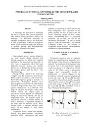
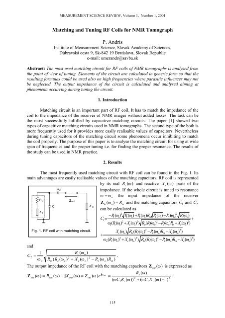
The most frequently used matching circuit with <strong>RF</strong> coil can be found in the Fig. 1. Its<br />
main advantages are easily realisable values of the matching capacitors. <strong>RF</strong> coil is represented<br />
by its real Rc<br />
(ω)<br />
and reactive X c (ω ) parts of the<br />
C2 impedance. If the whole circuit is tuned to resonance<br />
ω= ω the input impedance of the receiver<br />
R c<br />
Xc<br />
C1<br />
Zout<br />
Fig. 1. <strong>RF</strong> coil with matching circuit.<br />
and<br />
1<br />
C2<br />
=<br />
ω R ( R ( ω<br />
Rc<br />
( ω o )<br />
2<br />
2<br />
) + X ( ω ) − R ( ω ) R<br />
.<br />
)<br />
o<br />
in<br />
c<br />
o<br />
c<br />
o<br />
Z<br />
in<br />
c<br />
o<br />
Z in (ω o)<br />
= Rin<br />
and the matching capacitors 1 and C<br />
can be calculated as<br />
2<br />
2<br />
−Rc<br />
( ωo)<br />
Rc(<br />
ωo)<br />
+ Rc(<br />
ωo)<br />
Rin<br />
Rc(<br />
ωo)<br />
−Xc(<br />
ωo)<br />
Rc(<br />
ωo)<br />
C1<br />
=<br />
+<br />
2<br />
2<br />
2<br />
2<br />
ω ( R(<br />
ω ) + X ( ω ) ) R ( R(<br />
ω ) −R<br />
( ω ) R + X ( ω ) )<br />
o<br />
c<br />
o<br />
c<br />
o<br />
in<br />
c<br />
o<br />
c<br />
o<br />
in<br />
C 2<br />
2<br />
2<br />
Xc(<br />
ωo)<br />
Rin(<br />
Rc<br />
( ωo)<br />
−Rc<br />
( ωo)<br />
Rin<br />
+ Xc(<br />
ωo)<br />
)<br />
+<br />
2<br />
2<br />
2<br />
2<br />
ω ( R ( ω ) + X ( ω ) ) R ( R ( ω ) −R<br />
( ω ) R + X ( ω ) )<br />
o<br />
o<br />
The output impedance of the <strong>RF</strong> coil with the matching capacitors Z (ω)<br />
is expressed as<br />
Z<br />
out<br />
jϕ<br />
R ( ω)<br />
out<br />
c<br />
( ω)<br />
= Rout<br />
( ω)<br />
+ jX<br />
out ( ω)<br />
= Z out ( ω)<br />
e =<br />
2<br />
2<br />
( ωC<br />
R ( ω))<br />
+ ( ωC<br />
X ( ω)<br />
−1)<br />
c<br />
in<br />
115<br />
o<br />
1<br />
c<br />
c<br />
o<br />
in<br />
1<br />
c<br />
o<br />
out<br />
c<br />
c<br />
o<br />
+<br />
in<br />
c<br />
c<br />
o<br />
o
<strong>Measurement</strong> of Physical Quantities ● P. Andris<br />
2 2 2 2 2<br />
2 2 2 2 2<br />
ωC2<br />
X c ( ω)<br />
+ 2ωC1<br />
X c ( ω)<br />
−1−<br />
C1C2R<br />
c ( ω)<br />
ω −ω<br />
C1<br />
Rc<br />
( ω)<br />
−C1C<br />
2ω<br />
X c ( ω)<br />
−ω<br />
C1<br />
X c ( ω)<br />
+ j .<br />
2<br />
2<br />
ωC<br />
(( ωC<br />
R ( ω))<br />
+ ( ωC<br />
X ( ω)<br />
−1)<br />
)<br />
2<br />
1<br />
c<br />
A new coil is usually matched the first time by help capacitors C 1 and C2<br />
without any<br />
sample. On introducing the sample two couplings occur between the coil and the sample: the<br />
inductive and the capacitive. The inductive coupling is necessary <strong>for</strong> getting a signal from the<br />
experiment; the capacitive coupling is undesirable and causes losses. There<strong>for</strong>e the parameters<br />
of the coil Rc ( ω o ) and X c ( ω o ) can change unpredictably depending on parameters of the<br />
sample and Rc ( ω o ) can be considered as a constant and X c ( ω o ) = Lω<br />
o only as a special case<br />
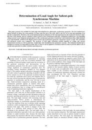
how it was described in [1]. At high frequencies moreover parasitic circuit elements influence<br />
the coil impedance and make it even more complex also without a sample. Fig. 2. a) and b)<br />
show real and reactive parts of the impedance Z (ω)<br />
varying as frequency <strong>for</strong> a typical <strong>RF</strong><br />
coil without parasitic influences and a sample matched at f = 4.<br />
45 MHz to the receiver with<br />
Rin<br />
= 50 Ω .<br />
a) real part b) reactive part<br />
Fig. 2. Output impedance of a typical <strong>RF</strong> coil matched to 50 Ω at 4.45 MHz.<br />
Although the coil should be matched only at one frequency, Zout<br />
(ω)<br />
has two points of the<br />
resonance. They can be calculated <strong>for</strong> an unloaded coil far from its own resonance as<br />
f<br />
1<br />
and<br />
f<br />
2<br />
1<br />
=<br />
2π<br />
2<br />
1<br />
=<br />
2π<br />
2<br />
2<br />
2 C2<br />
Rc<br />
+<br />
− − 2<br />
( C + C ) L C ( C + C ) L L<br />
1<br />
1<br />
2<br />
2<br />
1<br />
2<br />
2 C2<br />
Rc<br />
+<br />
− + 2<br />
( C + C ) L C ( C + C ) L L<br />
1<br />
1<br />
1<br />
2<br />
2<br />
out<br />
1<br />
1<br />
1<br />
c<br />
2<br />
o<br />
2<br />
−4C<br />
( C + C ) L + ( −2C<br />
L−<br />
C L + C R + C C R<br />
1<br />
1<br />
2<br />
1<br />
1<br />
1<br />
C ( C + C<br />
1<br />
1<br />
1<br />
2<br />
2<br />
2)<br />
L<br />
2<br />
−4C<br />
( C + C ) L + ( −2C<br />
L−C<br />
L+<br />
C R + C C R )<br />
2<br />
2<br />
2<br />
C ( C + C ) L<br />
The <strong>for</strong>mulas above were calculated considering that the impedance of the coil may be<br />
expressed as its inductance and resistance. It is possible only if the coil is far from its own<br />
resonance and if the coil impedance is not influenced with some couplings. Nevertheless such<br />
simplification was necessary because expressing the impedance of the coil in generic <strong>for</strong>m as<br />
a function of the frequencies f1 and f 2 would disable their calculation.<br />
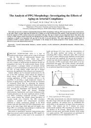
The dependence of the difference between the frequencies ∆f<br />
= f 2 − f1<br />
on the quality factor<br />
o L<br />
Q<br />
R<br />
ω<br />
= , X c ( ω ) = ω L is depicted in Fig. 3. The higher Q the closer are the frequencies 1 f<br />
c<br />
and f to each other. Very interesting can be the course of tuning at the resonant frequency<br />
2<br />
116<br />
2<br />
1<br />
2<br />
1<br />
2<br />
c<br />
2<br />
c<br />
1<br />
1<br />
2<br />
2<br />
2<br />
c<br />
)<br />
2<br />
c<br />
2<br />
2
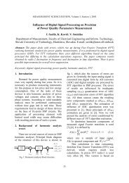
MEASUREMENT SCIENCE REVIEW, Volume 1, Number 1, 2001<br />
ω= ωo<br />
as shown in Fig. 4. a) and b) <strong>for</strong> the module and the argument of the output<br />
impedance depending on capacitors<br />
C1<br />
and C 2 . It is obvious that tuning<br />
by C1<br />
yields two items of resonance<br />
and only one of them is the proper.<br />
The capacitor C2<br />
on the other hand<br />
has main influence on the Rout<br />
value.<br />
The correct matching has to be set in<br />
co-operation of the both capacitors<br />
C1<br />
and C 2 . The values of the<br />
capacitors in the figures are typical<br />
<strong>for</strong> a typical coil. They can be easily<br />
realised by typical variable capacitors.<br />
The resonance occurs at two values of<br />
C1<br />
capacitor and the distance between the both capacitance values varying as the quality<br />
ω o L<br />
factor Q is depicted in the figure Fig. 5., considering Q = and X c oL<br />
. The higher the<br />
R<br />
ω =<br />
Fig. 3. Distance between the resonant frequencies,<br />
depending on quality factor of the coil.<br />
quality factor Q the smaller the value of C . C C − = ∆<br />
2X c ( ω o ) + C2<br />
R ) o + C2 X c ( ω o ) ) +<br />
2<br />
C12 = ( −ω<br />
( −<br />
c ( ω<br />
2<br />
2 2 o<br />
o ω<br />
ω o<br />
2(<br />
R ( ω ) + X ( ω ) ) ω<br />
1<br />
a) module b) argument<br />
Fig. 4. Output impedance of matched coil varying as tuning capacitors.<br />
2X c ( ω o ) + C2<br />
R<br />
o + ) ) −<br />
2<br />
) C2 X c ( ω o<br />
2<br />
c ( o ω<br />
The values of the both items of resonance capacitance can be calculated as<br />
C11<br />
=<br />
2(<br />
R ( ω<br />
1<br />
2<br />
) + X ( ω<br />
( −ω<br />
( −<br />
2 2 o<br />
ω<br />
) ) ω<br />
ω o<br />
−<br />
and<br />
+<br />
c<br />
o<br />
c<br />
o<br />
o<br />
12<br />
) X c ( ωo<br />
2<br />
o ω ( c o ω<br />
ω +<br />
) c ( o ω 2 ( ) )<br />
2<br />
2 2<br />
2<br />
2 2<br />
( −4(<br />
Rc ( o)<br />
+ X c(<br />
ω o)<br />
) ωo<br />
( 1−<br />
C2<br />
X c ( ωo ωo<br />
+ ωo<br />
− X + C2R<br />
C2<br />
) ωo)<br />
) )<br />
c<br />
o<br />
1 2<br />
c<br />
o<br />
o<br />
) Xc ( ωo<br />
2<br />
o ω ( ω o ) ω o +<br />
+ ( c ω 2 ( ) )<br />
2<br />
o ωo + ωo<br />
− X<br />
2 c R C<br />
2<br />
2 2<br />
2 2<br />
( −4(<br />
Rc ( o)<br />
+ Xc<br />
( ωo) ) ωo<br />
( 1−<br />
C2<br />
Xc<br />
( ω<br />
C2<br />
) ωo)<br />
) )<br />
The quality factor is an important parameter of an unloaded <strong>RF</strong> coil. The designed coil is<br />
usually characterised by its Q and capacity necessary to its tuning to resonance. Basing on the<br />
117<br />
11<br />
c
<strong>Measurement</strong> of Physical Quantities ● P. Andris<br />
two measured quantities, values of the capacitors C1 and C2<br />
can be calculated and the coil<br />
can be matched completing the calculated values by experimental results.<br />
Introducing a sample into the<br />
coil causes different couplings<br />
creating and the both parts of<br />
the coil impedance the real and<br />
the reactive become complex<br />
functions of frequency. Despite<br />
of that it is often assumed that<br />
introducing a sample simply<br />
influences the quality factor of<br />
the coil. Investigating the Q<br />
changes can thus provide<br />
approximate in<strong>for</strong>mation on<br />
variable capacitors span. The<br />
Fig. 5. Distance between the two capacitance values varying dependence of capacitance C 1<br />
as the quality factor.<br />
and C2<br />
, varying as Q can be<br />
observed in Fig. 6. a) and b)<br />
<strong>for</strong> a typical coil with R = 50Ω<br />
and = 4.<br />
45MHz<br />
.<br />
in<br />
f o<br />
a) b)<br />
Fig. 6. Values of matching capacitors varying as coil quality factor Q.<br />
The figures provide a good picture on tuning and matching problems. They can also give<br />
in<strong>for</strong>mation on sensitivity of the resulting capacity on changes of the coil quality factor.<br />
3. Conclusion<br />
Purpose of the paper was investigating phenomena occurring during tuning an <strong>RF</strong> coil<br />
<strong>for</strong> <strong>NMR</strong> tomograph. It is obvious that tuning a coil, mainly if new can bring some problems.<br />
The derived theory, depicted by many figures, can help solving such problems.<br />
Acknowledgement: The paper was written with support of the Grant Agency of the Slovak<br />
Academy of <strong>Science</strong>s, project VEGA no. 2/6020/21.<br />
References:<br />
[1] Andris, P.: Matching <strong>RF</strong> <strong>Coils</strong> <strong>for</strong> <strong>NMR</strong> <strong>Tomograph</strong>. Journal of Electrical Engineering /<br />
Elektrotechnický časopis 50, 1999, no. 5-6, pp. 147-150.<br />
[2] Wolfram, S.: Mathematica. Wolfram Research, Inc., Champaign, 1993.<br />
118