Tuning of the laser diode - Measurement Science Review
Tuning of the laser diode - Measurement Science Review
Tuning of the laser diode - Measurement Science Review

Create successful ePaper yourself
Turn your PDF publications into a flip-book with our unique Google optimized e-Paper software.
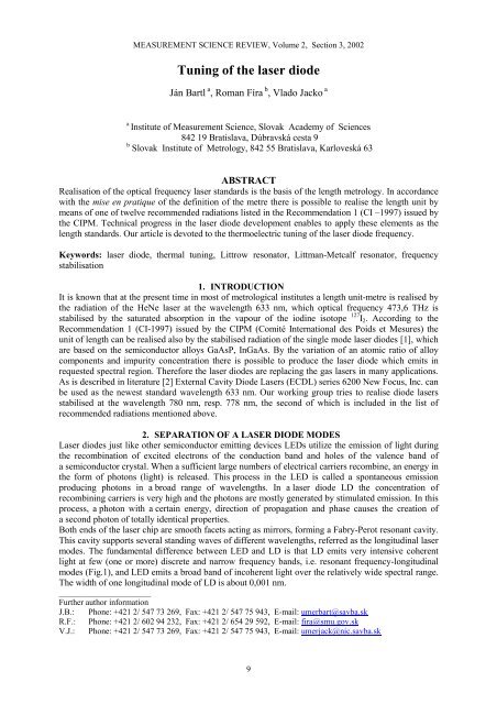
MEASUREMENT SCIENCE REVIEW, Volume 2, Section 3, 2002<br />
<strong>Tuning</strong> <strong>of</strong> <strong>the</strong> <strong>laser</strong> <strong>diode</strong><br />
Ján Bartl a , Roman Fíra b , Vlado Jacko a<br />
a Institute <strong>of</strong> <strong>Measurement</strong> <strong>Science</strong>, Slovak Academy <strong>of</strong> <strong>Science</strong>s<br />
842 19 Bratislava, Dúbravská cesta 9<br />
b Slovak Institute <strong>of</strong> Metrology, 842 55 Bratislava, Karloveská 63<br />
ABSTRACT<br />
Realisation <strong>of</strong> <strong>the</strong> optical frequency <strong>laser</strong> standards is <strong>the</strong> basis <strong>of</strong> <strong>the</strong> length metrology. In accordance<br />
with <strong>the</strong> mise en pratique <strong>of</strong> <strong>the</strong> definition <strong>of</strong> <strong>the</strong> metre <strong>the</strong>re is possible to realise <strong>the</strong> length unit by<br />
means <strong>of</strong> one <strong>of</strong> twelve recommended radiations listed in <strong>the</strong> Recommendation 1 (CI –1997) issued by<br />
<strong>the</strong> CIPM. Technical progress in <strong>the</strong> <strong>laser</strong> <strong>diode</strong> development enables to apply <strong>the</strong>se elements as <strong>the</strong><br />
length standards. Our article is devoted to <strong>the</strong> <strong>the</strong>rmoelectric tuning <strong>of</strong> <strong>the</strong> <strong>laser</strong> <strong>diode</strong> frequency.<br />
Keywords: <strong>laser</strong> <strong>diode</strong>, <strong>the</strong>rmal tuning, Littrow resonator, Littman-Metcalf resonator, frequency<br />
stabilisation<br />
1. INTRODUCTION<br />
It is known that at <strong>the</strong> present time in most <strong>of</strong> metrological institutes a length unit-metre is realised by<br />
<strong>the</strong> radiation <strong>of</strong> <strong>the</strong> HeNe <strong>laser</strong> at <strong>the</strong> wavelength 633 nm, which optical frequency 473,6 THz is<br />
stabilised by <strong>the</strong> saturated absorption in <strong>the</strong> vapour <strong>of</strong> <strong>the</strong> iodine isotope 127 I2. According to <strong>the</strong><br />
Recommendation 1 (CI-1997) issued by <strong>the</strong> CIPM (Comité International des Poids et Mesures) <strong>the</strong><br />
unit <strong>of</strong> length can be realised also by <strong>the</strong> stabilised radiation <strong>of</strong> <strong>the</strong> single mode <strong>laser</strong> <strong>diode</strong>s [1], which<br />
are based on <strong>the</strong> semiconductor alloys GaAsP, InGaAs. By <strong>the</strong> variation <strong>of</strong> an atomic ratio <strong>of</strong> alloy<br />
components and impurity concentration <strong>the</strong>re is possible to produce <strong>the</strong> <strong>laser</strong> <strong>diode</strong> which emits in<br />
requested spectral region. Therefore <strong>the</strong> <strong>laser</strong> <strong>diode</strong>s are replacing <strong>the</strong> gas <strong>laser</strong>s in many applications.<br />
As is described in literature [2] External Cavity Diode Lasers (ECDL) series 6200 New Focus, Inc. can<br />
be used as <strong>the</strong> newest standard wavelength 633 nm. Our working group tries to realise <strong>diode</strong> <strong>laser</strong>s<br />
stabilised at <strong>the</strong> wavelength 780 nm, resp. 778 nm, <strong>the</strong> second <strong>of</strong> which is included in <strong>the</strong> list <strong>of</strong><br />
recommended radiations mentioned above.<br />
2. SEPARATION OF A LASER DIODE MODES<br />
Laser <strong>diode</strong>s just like o<strong>the</strong>r semiconductor emitting devices LEDs utilize <strong>the</strong> emission <strong>of</strong> light during<br />
<strong>the</strong> recombination <strong>of</strong> excited electrons <strong>of</strong> <strong>the</strong> conduction band and holes <strong>of</strong> <strong>the</strong> valence band <strong>of</strong><br />
a semiconductor crystal. When a sufficient large numbers <strong>of</strong> electrical carriers recombine, an energy in<br />
<strong>the</strong> form <strong>of</strong> photons (light) is released. This process in <strong>the</strong> LED is called a spontaneous emission<br />
producing photons in a broad range <strong>of</strong> wavelengths. In a <strong>laser</strong> <strong>diode</strong> LD <strong>the</strong> concentration <strong>of</strong><br />
recombining carriers is very high and <strong>the</strong> photons are mostly generated by stimulated emission. In this<br />
process, a photon with a certain energy, direction <strong>of</strong> propagation and phase causes <strong>the</strong> creation <strong>of</strong><br />
a second photon <strong>of</strong> totally identical properties.<br />
Both ends <strong>of</strong> <strong>the</strong> <strong>laser</strong> chip are smooth facets acting as mirrors, forming a Fabry-Perot resonant cavity.<br />
This cavity supports several standing waves <strong>of</strong> different wavelengths, referred as <strong>the</strong> longitudinal <strong>laser</strong><br />
modes. The fundamental difference between LED and LD is that LD emits very intensive coherent<br />
light at few (one or more) discrete and narrow frequency bands, i.e. resonant frequency-longitudinal<br />
modes (Fig.1), and LED emits a broad band <strong>of</strong> incoherent light over <strong>the</strong> relatively wide spectral range.<br />
The width <strong>of</strong> one longitudinal mode <strong>of</strong> LD is about 0,001 nm.<br />
______________________<br />
Fur<strong>the</strong>r author information<br />
J.B.: Phone: +421 2/ 547 73 269, Fax: +421 2/ 547 75 943, E-mail: umerbart@savba.sk<br />
R.F.: Phone: +421 2/ 602 94 232, Fax: +421 2/ 654 29 592, E-mail: fira@smu.gov.sk<br />
V.J.: Phone: +421 2/ 547 73 269, Fax: +421 2/ 547 75 943, E-mail: umerjack@nic.savba.sk<br />
9
<strong>Measurement</strong> <strong>of</strong> Physical Quantities ● J. Bartl , R. Fíra, V. Jacko<br />
The single-mode emission can be achieved by employing <strong>the</strong> frequency selecting element, such as<br />
a grating, in order to pick up <strong>the</strong> desired wavelength from <strong>the</strong> resonator modes. One way <strong>of</strong> generating<br />
<strong>of</strong> such a narrow spectral bandwidth is to place <strong>the</strong> grating directly inside <strong>the</strong> resonator. This solution<br />
is known as <strong>the</strong> distributed feedback <strong>laser</strong> DFB (Fig.2a).<br />
771 774 777 780 783<br />
Wavelength λ (nm)<br />
10<br />
∆λ = 0,35 nm<br />
Fig.1 Spectral distribution <strong>of</strong> GaAsP <strong>laser</strong><br />
O<strong>the</strong>r construction is to place <strong>the</strong> grating parallel to <strong>the</strong> junction plane. Such a single-mode <strong>laser</strong> is<br />
known as <strong>the</strong> distributed Bragg reflector DBR (Fig.2b). In both cases <strong>the</strong> supplied pump energy is<br />
comprised in only one mode. The emitted wavelength is fixed by <strong>the</strong> separation <strong>of</strong> <strong>the</strong> grating lines<br />
and <strong>the</strong> frequency can be altered both <strong>the</strong>rmally or by <strong>the</strong> <strong>diode</strong> current. The single-mode emission can<br />
be also achieved by <strong>the</strong> external resonator with grating, <strong>the</strong> so-called external cavity <strong>diode</strong> <strong>laser</strong><br />
ECDL. Nowadays, two basic arrangements <strong>of</strong> external resonators are known: Littrow’s [3] and that <strong>of</strong><br />
Fig.2 Resonators for single-mode <strong>laser</strong>s
MEASUREMENT SCIENCE REVIEW, Volume 2, Section 3, 2002<br />
Littman-Metcalf’s [4]. In <strong>the</strong> Littrow`s construction a slope change <strong>of</strong> an external grating to <strong>the</strong> output<br />
<strong>laser</strong> beam (Fig.2c) tunes <strong>the</strong> single-mode wavelength. In <strong>the</strong> Littman-Metcalf’s resonator <strong>the</strong><br />
grating has a fixed slope to <strong>the</strong> output <strong>laser</strong> beam. The separation <strong>of</strong> desired mode is ensured by <strong>the</strong><br />
inclination <strong>of</strong> <strong>the</strong> tuning mirror (Fig.3) [5].<br />
Fig.3 Littman resonator. Turning <strong>the</strong> mirror S2 around a point P, <strong>the</strong><br />
angle between S2 and G changes , and wavelength is tuned.<br />
3. THERMOELECTRIC TUNING OF THE LASER DIODE WAVELENGTH<br />
To obtain a single mode spectrum, one must suppress <strong>the</strong> side modes. At low operating currents Iop <strong>the</strong><br />
<strong>laser</strong> <strong>diode</strong> emits a multimode spectrum. The side modes are progressively suppressed as <strong>the</strong> Iop<br />
increases to some maximum value (Fig.4). The optical spectrum <strong>of</strong> <strong>laser</strong> <strong>diode</strong>s becomes narrower<br />
with increasing <strong>of</strong> <strong>the</strong> power levels. The corresponding shift <strong>of</strong> <strong>the</strong> central wavelength to <strong>the</strong> higher<br />
output optical power is due to internal heating <strong>of</strong> <strong>the</strong> chip by <strong>the</strong> transient current Iop.<br />
Fig.4 Optical spectra at various operating currents<br />
That causes a change <strong>of</strong> a band-gap (energy level) in <strong>the</strong> crystal. If ∆Eg is width <strong>of</strong> <strong>the</strong> forbidden band,<br />
<strong>the</strong> dependence <strong>of</strong> ∆Eg on <strong>the</strong> absolute temperature T is given by <strong>the</strong> expression [6]:<br />
∆Eg = ∆Ego<br />
( 1 − αT<br />
)<br />
(1)<br />
where ∆Eg is <strong>the</strong> width <strong>of</strong> forbidden band at T = 0 K, α is a <strong>the</strong>rmal coefficient (α > 1.10 -4 K -1 )<br />
characteristic for <strong>the</strong> given semiconductive material.<br />
11
<strong>Measurement</strong> <strong>of</strong> Physical Quantities ● J. Bartl , R. Fíra, V. Jacko<br />
The dependence <strong>of</strong> emitted wavelength λ on <strong>the</strong> ∆Eg is given by <strong>the</strong> following equation:<br />
hc 1240,<br />
6<br />
λ = =<br />
(2)<br />
∆Eg<br />
∆Eg<br />
where ∆Eg is in eV and λ in nm.<br />
Increasing <strong>of</strong> <strong>the</strong> <strong>laser</strong> chip temperature causes <strong>the</strong> narrowing <strong>of</strong> <strong>the</strong> energy band gap, while <strong>the</strong> optical<br />
spectrum shifts towards <strong>the</strong> longer wavelengths. Simultaneously, <strong>the</strong> <strong>laser</strong> <strong>diode</strong> dimension L (cca. 250<br />
µm) <strong>of</strong> <strong>the</strong> <strong>laser</strong> cavity increases as <strong>the</strong> consequence <strong>of</strong> <strong>the</strong>rmal extension. It follows:<br />
2<br />
2nL<br />
λ<br />
λ = and ∆λ<br />
=<br />
(3)<br />
q<br />
2ng<br />
L<br />
where q is <strong>the</strong> mode number (see Fig.1), n is <strong>the</strong> refractive index at <strong>the</strong> central wavelength λ, ng is <strong>the</strong><br />
group index <strong>of</strong> refraction (mean value n for emitted expressive modes, usually ng ≥ n).<br />
The typical wavelength <strong>the</strong>rmal shift is about 0,25nm/°C– 0,3nm/°C for <strong>laser</strong> <strong>diode</strong>s in <strong>the</strong> visible<br />
region. In such a way, i.e. by <strong>the</strong> <strong>the</strong>rmal tuning, <strong>the</strong>re is possible to achieve <strong>the</strong> requested wavelength<br />
in a certain range. The typical tuning curves for some <strong>laser</strong>s are shown in <strong>the</strong> Fig.5. The two curves<br />
represent <strong>the</strong> maximum and minimum power over a tuning range <strong>of</strong> about 0.1 nm (adopted from [2]).<br />
Fig.5 Typical tuning curve <strong>of</strong> a Model 6304 Typical tuning curve <strong>of</strong> a Model 6312<br />
New Focus Inc New Focus Inc<br />
For most <strong>of</strong> <strong>laser</strong> <strong>diode</strong>s, <strong>the</strong> threshold current (defined as <strong>the</strong> point where <strong>the</strong> emission <strong>of</strong> a higher<br />
power coherent light starts, i.e. operates as <strong>the</strong> <strong>laser</strong>) increases exponentially with <strong>the</strong> temperature<br />
increase. In accordance with this fact, a tuning <strong>of</strong> <strong>laser</strong> is possible only in a narrow spectral band. The<br />
minimum tuning range is typically 10 nm for <strong>laser</strong>s λ ∈ 632 − 637 nm , e.g. <strong>diode</strong> <strong>laser</strong>s No. 6005,<br />
No.6210, No.6211, No.6304, No.6305 (New Focus) and 15 nm for <strong>laser</strong>s λ = 745 − 785 nm , e.g. <strong>laser</strong>s<br />
No.6013, No.6224, No.6225, No.6312, No.6313. It is necessary to note that <strong>the</strong> <strong>the</strong>rmal tuning is<br />
accompanied with longitudinal mode hopping (see [8]). For <strong>the</strong> multimode <strong>laser</strong> <strong>diode</strong>s <strong>the</strong> mode hops<br />
are not visible due to <strong>the</strong> large number <strong>of</strong> modes and <strong>the</strong> relatively small energy associated with each<br />
mode. For <strong>the</strong> singlemode <strong>laser</strong> <strong>diode</strong> <strong>the</strong> mode hops manifest very intense (Fig.6).<br />
Fig.6 Typical mode hops for <strong>the</strong> singlemode Typical linear dependence <strong>of</strong> wavelength vs.<br />
<strong>laser</strong> <strong>diode</strong> Sharp LT027 temperature for a multimode <strong>diode</strong> LT023<br />
12
MEASUREMENT SCIENCE REVIEW, Volume 2, Section 3, 2002<br />
To avoid <strong>the</strong>se instabilities (discrete points), a <strong>laser</strong> <strong>diode</strong> shall be temperature stabilized using<br />
a <strong>the</strong>rmoelectric cooler (Peltier element).<br />
The standard laboratory type power supply should not be used to operate <strong>laser</strong> <strong>diode</strong>s. For <strong>the</strong><br />
operation <strong>of</strong> <strong>the</strong> <strong>laser</strong> <strong>diode</strong>s only power supplies with slow-start circuits (i.e. with current transient<br />
suppression and a current limit exceeding <strong>the</strong> <strong>laser</strong> <strong>diode</strong>'s maximum current limit) can be used. Laser<br />
<strong>diode</strong> drivers usually serve in two modes <strong>of</strong> operation, constant current or constant power, with<br />
adjustable current limit control. The principal scheme <strong>of</strong> such driver is shown in <strong>the</strong> Fig.7.<br />
Fig.7 Block diagram <strong>of</strong> a typical <strong>laser</strong> <strong>diode</strong> power control<br />
system with optical feedback and <strong>the</strong>rmoelectric tuning<br />
4. FINAL STABILIZATION OF A LASER DIODE FREQUENCY<br />
However, in order to achieve <strong>the</strong> high frequency stability and reproducibility that all <strong>the</strong> radiations<br />
used for <strong>the</strong> realisation <strong>of</strong> <strong>the</strong> length unit must have, <strong>the</strong> frequency <strong>of</strong> a <strong>diode</strong> <strong>laser</strong> requires to be<br />
somehow locked to <strong>the</strong> value relatively independent on <strong>the</strong> various parameters. The most general way<br />
<strong>of</strong> locking <strong>the</strong> frequency is to use a saturated absorption <strong>of</strong> <strong>laser</strong> radiation, passing through <strong>the</strong><br />
absorbing medium. Some chemical elements, such as an iodine molecule or atomic rubidium have<br />
absorption lines possessing a hyperfine structure with a very narrow peaks, which frequencies are well<br />
known and <strong>the</strong>refore may be used for <strong>the</strong> frequency stabilisation <strong>of</strong> <strong>the</strong> <strong>laser</strong> radiation.<br />
In <strong>the</strong> case <strong>of</strong> rubidium, <strong>the</strong>re may be chosen too ways :<br />
1. stabilisation at <strong>the</strong> one-photon transition (5S – 5P) 384,2 THz (780 nm) in 87 Rb<br />
2. stabilisation at <strong>the</strong> two-photon transition (5S – 5D) 385 THz (778 nm) in 85 Rb.<br />
1. The stabilisation at <strong>the</strong> one-photon transition is well known and is similar to <strong>the</strong> commonly used<br />
frequency stabilisation in <strong>the</strong> iodine vapour. In this case only particles (atoms Rb or molecules I2) with<br />
<strong>the</strong> given value <strong>of</strong> longitudinal velocity interact with <strong>the</strong> <strong>laser</strong> beam. When <strong>the</strong> <strong>laser</strong> <strong>diode</strong> frequency is<br />
tuned and <strong>the</strong> value <strong>of</strong> <strong>the</strong> absorbing transition is achieved, so that only atoms with zero longitudinal<br />
velocity interact, <strong>the</strong> phenomenon called saturated absorption takes place and <strong>the</strong> dopplerless peaks<br />
occur at <strong>the</strong> absorbing power curve. This is because <strong>of</strong> <strong>the</strong> absorbing medium is inside <strong>the</strong> resonator<br />
cavity, two opposite beams are passing through it and <strong>the</strong> same atoms interact with both beams. In this<br />
case, <strong>the</strong> probability <strong>of</strong> <strong>the</strong> quantum transition is relatively high, but <strong>the</strong> number <strong>of</strong> interacting atoms is<br />
small.<br />
2. Two-photon transition is <strong>the</strong> quantum transition between two levels <strong>of</strong> 85 Rb <strong>of</strong> corresponding<br />
frequency 770 THz (389 nm). It corresponds to <strong>the</strong> simultaneous absorption <strong>of</strong> two photons (each <strong>of</strong><br />
13
<strong>Measurement</strong> <strong>of</strong> Physical Quantities ● J. Bartl , R. Fíra, V. Jacko<br />
<strong>the</strong>m 385 THz). In <strong>the</strong> case, that <strong>the</strong>se two photons have opposite directions and <strong>the</strong> frequency <strong>of</strong> <strong>laser</strong><br />
<strong>diode</strong> is tuned to <strong>the</strong> half <strong>of</strong> <strong>the</strong> transition frequency, <strong>the</strong> sum <strong>of</strong> energies <strong>of</strong> both photons is equal for<br />
almost all absorbing particles inside both opposite <strong>laser</strong> beams. The Doppler shift <strong>of</strong> two opposite<br />
photons is in <strong>the</strong> sum mutually compensated. The frequency <strong>of</strong> virtual transition 385 THz (778 nm) is<br />
relatively close to <strong>the</strong> frequency <strong>of</strong> one-photon transition 384,2 THz (780 nm) and thus <strong>the</strong> probability<br />
<strong>of</strong> <strong>the</strong> absorption is slightly different from zero. This small probability is fully compensated by <strong>the</strong><br />
number <strong>of</strong> interacting atoms, that is not restricted only to those having a longitudinal velocity equal to<br />
zero, i.e. moving perpendicularly to <strong>the</strong> optical axis. When <strong>the</strong> frequency <strong>of</strong> <strong>the</strong> <strong>laser</strong> <strong>diode</strong> is not<br />
tuned to <strong>the</strong> transition frequency, no atom will interact with <strong>the</strong> beam.<br />
Fig.8 The experimental arrangement <strong>of</strong> <strong>the</strong> <strong>diode</strong> <strong>laser</strong> with <strong>the</strong> <strong>laser</strong> driver and<br />
<strong>the</strong>rmoelectric controller built at Slovak institute <strong>of</strong> metrology in 2000<br />
In <strong>the</strong> case <strong>of</strong> using <strong>the</strong> two-photon transition, <strong>the</strong> absorbing peak is very narrow and <strong>the</strong> absorbing<br />
curve is not sloping, i.e. no third harmonics technique is necessary for <strong>the</strong> frequency stabilisation.<br />
5. CONCLUSION<br />
Laser <strong>diode</strong>s are much smaller, require less voltage, less power supply and due to much higher density<br />
<strong>of</strong> <strong>the</strong> active medium (comparing to gas <strong>laser</strong>s) <strong>the</strong> higher output power can be achieved. They are<br />
highly reliable and <strong>the</strong>ir lifetime exceeds that <strong>of</strong> gas <strong>laser</strong>s. Therefore <strong>the</strong> <strong>laser</strong> <strong>diode</strong>s have found<br />
application also in <strong>the</strong> field <strong>of</strong> length metrology. Since <strong>the</strong> stabilisation <strong>of</strong> frequency for <strong>the</strong> length<br />
metrology purposes is realised only at determined frequencies, corresponding to quantum transitions in<br />
chosen atoms, ions or molecules ( 1 H, 40 Ca, 88 Sr + , 85 Rb, 87 Rb, 127 I2, 129 I2, CH4, OsO4), <strong>the</strong> <strong>laser</strong> <strong>diode</strong><br />
must be tuned to <strong>the</strong>se frequency values. In our article we have described <strong>the</strong> ECDL technique <strong>of</strong> <strong>the</strong><br />
<strong>laser</strong> mode separation and <strong>the</strong> method <strong>of</strong> <strong>the</strong>rmoelectric tuning <strong>of</strong> <strong>the</strong> <strong>laser</strong> <strong>diode</strong> frequency. Last<br />
chapter is devoted to <strong>the</strong> physical principle <strong>of</strong> <strong>the</strong> precise stabilisation <strong>of</strong> <strong>the</strong> <strong>laser</strong> <strong>diode</strong> frequency. We<br />
have focussed on <strong>the</strong> brief and simplified description <strong>of</strong> <strong>the</strong> frequency stabilisation at both one and two<br />
photon transition in RBA vapour with frequencies 384,2 Hz and 385 Hz respectively. These research<br />
problems are now in <strong>the</strong> foreground <strong>of</strong> <strong>the</strong> length laboratory <strong>of</strong> Slovak institute <strong>of</strong> metrology.<br />
14
MEASUREMENT SCIENCE REVIEW, Volume 2, Section 3, 2002<br />
This article summarises <strong>the</strong> new knowledges in <strong>the</strong> development <strong>of</strong> <strong>the</strong> metrological <strong>laser</strong>s which were<br />
described in periodicals [2],[3],[5] and [8].<br />
6. ACKNOWLEDGEMENT<br />
Authors are grateful to <strong>the</strong> Slovak Grant Agency for <strong>Science</strong> VEGA for <strong>the</strong> Financial support <strong>of</strong> <strong>the</strong><br />
research project No.2/1133/21.<br />
7. REFERENCES<br />
[1] NAVRATIL, V.: 9 th meeting <strong>of</strong> <strong>the</strong> Consultative Committee for Metre Definition-CCDM and <strong>the</strong><br />
equivalence <strong>of</strong> <strong>the</strong> national standards. Metrology and testing (In Slovak), 3, No.2, pp.18-20. 1998<br />
[2] NEW FOCUS, Inc.: Tuneable <strong>diode</strong> <strong>laser</strong>s for every application. Catalogue, Vol.8, , pp.14-25,<br />
Santa Clara US, 1997/98<br />
[3] KAENDERS, W. Littrow <strong>diode</strong> <strong>laser</strong>s catch <strong>the</strong> attention <strong>of</strong> industry. Euro Photonics, Dec./<br />
January 1998, pp.30-31<br />
[4] BARTL, J.- NAVRATIL, V.- FIRA, R.: New trends in <strong>the</strong> realisation <strong>of</strong> <strong>the</strong> unit <strong>of</strong> <strong>the</strong> quantity<br />
<strong>of</strong> length. Metrology and testing (In Slovak), 3, No.2, pp.7-10, 1998<br />
[5] LUTZ, J.: Antireflection coatings boost <strong>laser</strong> <strong>diode</strong>s` range. Euro Photonics, pp.42-43, April/<br />
May 1998<br />
[6] BARTL, J.- BARTOK, K.: Increasing <strong>of</strong> luminous efficiency <strong>of</strong> LED <strong>diode</strong>s at <strong>the</strong> cryogenic<br />
temperature. Proc. Photonics`92. pp.242-246, Rozvid 1992, Praha<br />
[7] SALEH, B.E.A.- TEICH, M.C.: Fundamentals <strong>of</strong> photonics. Vol. 3, pp.480-722,<br />
Matfyzpress (In Czech), Praha, 1995,<br />
[8] SEASTAR OPTICS, Inc: Optical Devices & Laser Diode Instrumentation. Product<br />
Catalog. 1993, p.10<br />
15