MANUAL 301 Mk9 - Liteville
MANUAL 301 Mk9 - Liteville
MANUAL 301 Mk9 - Liteville

Create successful ePaper yourself
Turn your PDF publications into a flip-book with our unique Google optimized e-Paper software.
<strong>MANUAL</strong> <strong>301</strong> <strong>Mk9</strong><br />
Please look for the newest updates of this manual at www.liteville.com > service > manual<br />
and at liteville.com
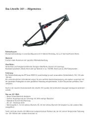
Limits for the <strong>Liteville</strong> <strong>301</strong> Frame<br />
Please be aware, not all parts available on the market can be used on the <strong>Liteville</strong> <strong>301</strong> frame and some parts<br />
simply should not be used! The following parts have limits:<br />
Fork<br />
Only forks with a maximum built height of 565 mm are permitted for use.<br />
Crank/Bottom Bracket<br />
Look for clearance<br />
Not all available crank/bottom bracket<br />
units can be used. The bottom bracket<br />
shell width is 73mm.<br />
Make sure the left crank does not collide<br />
with the left chain stay. Since the <strong>Liteville</strong><br />
<strong>301</strong> frame is only suitable for Shimano E-<br />
Type front derailleurs you need a bottom<br />
bracket that can be used with one.<br />
Seatpost<br />
The <strong>Liteville</strong> <strong>301</strong> frame needs a seatpost with a diameter of 34.9 mm.<br />
To prevent frame damage, the seatpost<br />
needs to be inserted down to the mark on<br />
the seat tube. Frames with Works Finish<br />
do not have a laser etching. Nevertheless,<br />
you need to adhere to the minimum<br />
inserting depth (120 / 140mm, see picture<br />
on left). Note that the minimum insertion<br />
depth is dependent on length of the<br />
seatpost length above the seat tube<br />
(below or above 200mm).<br />
Simply stated: if the seat post is pulled<br />
out more than 200mm (upper edge of<br />
seat tube to seat rails) only the lower<br />
laser etching is valid!<br />
2
Wheels/Tires<br />
The <strong>Liteville</strong> <strong>301</strong> frame is compatible with tires up to 2.5“. Frames size S and XS have limited clearance in the<br />
area of the chain stay yoke due to shorter chain stays. The <strong>301</strong> XS frame from <strong>Mk9</strong> onwards is exclusively<br />
designed for use with a 24” rear wheel.<br />
Seat clamp<br />
In case you do not want to use the original Syntace clamp you need a clamp with a diameter of 38mm due to<br />
the oversize build of the seat tube. Watch for enough clearance of the rear triangle during compression. To<br />
test, deflate shock completely and carefully compress the rear entirely.<br />
Shifter cable<br />
For a trouble-free installation use cable housing with a 4 mm outside diameter, for example Shimano SIS-<br />
SP41.<br />
Rear shock / Shock mounts<br />
Do not use shocks with an installation length other than 190 mm. Shock stroke can not exceed 50 mm.<br />
Tip: The <strong>Liteville</strong> <strong>301</strong> frame has a special low-ratio suspension design and does not work well with every<br />
shock available. Our shocks have been specifically tuned for our frames.<br />
Hint: A slight brush of the rear wheel at full compression is nothing to worry about. It will damage nothing and<br />
may only leave a brush mark on the seat tube.<br />
Brakes<br />
The <strong>Liteville</strong> <strong>301</strong> frame has been designed exclusively for use with disc brakes. From Mk8 onwards, the<br />
frame comes with 7” PM tabs allowing the use of PM disc brake callipers directly without the necessity for<br />
an adapter. For the use of rotors > than 180 mm, please contact your respective brake manufacturer. The<br />
minimum rear rotor diameter is 180 mm and the maximum diameter is 210 mm.<br />
3
Installation<br />
Frame preparation<br />
The contact surfaces for bearings and brakes etc. have already been prepped at the factory – you do not<br />
need to surface anything to install headset, bottom bracket or brakes.<br />
Headset / fork<br />
The headset bearings have been pressed into the frame by the factory. In case you need to change bearings,<br />
do not forget to use grease and make sure the bearings are pressed in evenly and completely. It is best to<br />
use a special tool for the task.<br />
Fork installation<br />
First, install both seals (grey lip on the outside, black o-ring on the inside) on<br />
the cover of the SuperSpin headset.<br />
Install the larger of the two slotted rings (the base plate, see picture) onto the<br />
steerer tube. Insert the steerer tube into the head tube, add the smaller slotted<br />
ring onto the steerer tube and install the black cover plate. Make sure the fork<br />
does not collide with the frame when turning.<br />
Now slide the lower (depending on fork, either the tapered or the 1 1/8” one) of the two slotted bearing cones<br />
onto the steerer tube. If using a 1 1/8” fork you now need to install the lower 1 1/8” reducer in the lower bearing<br />
(do not forget to grease).<br />
Insert fork into the frame, slide upper 1 1/8” cone onto steerer tube and install the cover plate.<br />
SuperSpin tapered, lower<br />
1.5, upper 1 1/8<br />
SuperSpin 1 1/8 with reducer<br />
for 11/8 steerer tubes<br />
Tip 1: Before installing the cover plate, grease bearing heavily. It will keep moisture away and aids easy<br />
spinning.<br />
Tip 2: Pull the headset tight with the adjustment bolt, then loosen the bolt again. Only now adjust bearing<br />
play. With that procedure you can make sure that the bearings have been seated correctly and will spin<br />
easily.<br />
4
Make sure the fork does not hit the down tube when spinning the bar.<br />
Bar / Stem<br />
Install bar and stem according to manufacturer’s instructions onto the steerer tube.<br />
Hint: test ride first with uncut steerer tube. You would not be the first person to be ticked off because you cut<br />
the steerer tube too short!<br />
Shift levers<br />
Install levers according to manufacturer’s specifications.<br />
Bottom bracket / crank & front derailleur<br />
Liberally grease contact surfaces for the bottom bracket. Fix the E-Type derailleur with the bolt (supplied by<br />
Shimano).<br />
Important: Do not use a spacer between BB and derailleur.<br />
Now install both BB bearing cups according to installation instructions. Use enough grease! From experience<br />
we know that especially outboard bearings tend to creak if not enough grease has been applied to the contact<br />
surfaces.<br />
Now tighten the 5 mm Allen screw of the derailleur according to manufacturers specifications and install<br />
crankset. Make sure there is enough room for rotation between crank arms and frame – test for enough<br />
clearance.<br />
Installing cables on the bottom tube<br />
Below the cable clamps you will find pre-installed pads. They are not glued! We recommend affixing them<br />
while installing shifter cables and brake lines.<br />
To do, degrease the frame in the area of installation.<br />
Remove aluminium bolt, cable clamp and pad, and then<br />
remove brown backing of pads. Stick the pads to the<br />
frame as you see in the picture, above the threading.<br />
Now you can mount the rear shifter cable and the rear<br />
brake line on top of the pads to achieve an optimal<br />
routing. Make sure the front, “half”, cable clamps face<br />
inwards with their tongues.<br />
5
Installation of HammerSchmidt<br />
Note: For <strong>Mk9</strong> onwards no more special Titanium bolt is<br />
required at the chain stay main pivot point in order to use<br />
the Hammerschmidt.<br />
Add the included HammerSchmidt adapter (with a little grease) to the ISCG mount and install the Hammer-<br />
Schmidt crank according to specs.<br />
Hint: The included HammerSchmidt adapter is specific to every individual frame. It cannot be swapped with<br />
another frame.<br />
Cable routing for HammerSchmidt<br />
To install cabling for HammerSchmidt,<br />
you need to exchange 3 clamps on the<br />
bottom tube.<br />
First, replace the single clamp through<br />
a double clamp from further down. The<br />
shifter cable for the HammerSchmidt<br />
crank will be routed in parallel to the rear<br />
shifter cable on the outside.<br />
Replace the two first clamps installed to<br />
the bottom tube by the triple clamps from<br />
the HammerSchmidt kit. Behind the last<br />
triple clamp the shifter cable will go<br />
directly into the HammerSchmidt crank<br />
housing.<br />
Cable routing with installed bottle cage<br />
• Either route cable in the area of bottle cage with small plastic clamps.<br />
• Or use shrink tube (preferably thick walled stuff like Hellermann Tyton) to route in parallel to shifter cable<br />
6
Without bottle cage<br />
• Install an additional <strong>Liteville</strong> “HammerSchmidt cable clamp” onto the second bottle cage inser<br />
• Use shrink tubing as described above<br />
Cable routing for front derailleur (without HammerSchmidt)<br />
Before you can install the cable housing,<br />
you need to unbolt the front shock mount<br />
and fold down the shock. To mount the<br />
cable housing, you will find special<br />
mounts on the bottom side of the top<br />
tube.<br />
insert only far enough so the tip snaps over the little cross ridge.<br />
Proceed as follows:<br />
Sharply bend a zip tie about 10 – 15 mm<br />
behind the tip so get something close<br />
to a hook. Now insert the hooked zip<br />
tie into the cable mount. Make sure you<br />
By pulling and pushing, you can direct<br />
the zip tie all the way through until the<br />
head is at the top tube. Now you can install<br />
the cable housing (and the optional<br />
cable housing for an adjustable seat<br />
post. Note: only pull the zip tie tight by<br />
hand!<br />
Cut the zip tie right at the head and turn<br />
the heads all the way to the top tube so<br />
they do not stick out.<br />
7
The shifter cable is running between top<br />
tube and shock. Let the shifter cable run<br />
through left rear shock mount and seat<br />
tube. The shifter housing for the E-type<br />
derailleur should neither run in a large<br />
arch nor in a very “direct” way to ensure<br />
good function.<br />
Cable routing for the rear derailleur<br />
The shifter cable for the rear derailleur is<br />
being routed directly through the seat<br />
tube into the chain stay. To protect the<br />
cable even better from corrosion, we use<br />
an additional, flexible tube.<br />
Hint: Do not remove the transparent plastic tube. In case you did remove it, reinstall it by pushing it thoroughly<br />
into its seat (blue in the picture) and do NOT use lubrication.<br />
The exit for the shifter cable is at the<br />
lower end of the right chain stay.<br />
8
Changing a shifter cable housing<br />
• Leave the transparent tube in place<br />
• Cut the new cable housing in a skewed fashion<br />
• Spray a little silicone spray into the guide<br />
tube<br />
• Insert shifter cable from the front until it<br />
is at the chain stay yoke<br />
• Use the rest of the cable housing as a<br />
handle by rolling it up. Let the housing<br />
find its way by turning and pushing at the<br />
same time. It will work even easier if the<br />
rear triangle will be moved up and down<br />
by about 1 – 2cm (remove shock mount).<br />
• Now cut the ends of the housing as usual. Done!<br />
• Push further until the housing hits the<br />
Horst link and let it find its way though<br />
the hole by turning and pushing<br />
9
Routing of brake line<br />
The brake lines and shifter cables are<br />
being routed continuously. Please to not<br />
over-tighten the bolts of the clamps to<br />
avoid crimping. If crimped, shifting and<br />
braking lines will lose function.<br />
Be aware that the brake line will be<br />
shortened during compression. Leave it<br />
long enough!<br />
Use the included clips for mounting the brake line on the left chain stay. If you use zip ties, squeaking noises<br />
may occur.<br />
Be aware: The routing pictured is for brake callipers where you can turn the line towards the rear. It<br />
will vary with other brake models.<br />
Rear derailleurs from Shimano:<br />
All derailleurs starting from model year 2009 will work (only Shadow!). Installation of old derailleurs (with the<br />
large diameter housing bend) is not recommended on <strong>Liteville</strong> <strong>301</strong> frames from Mk8 on because they do not<br />
harmonize well with the new, low-profile routing.<br />
Rear derailleurs from SRAM:<br />
SRAM X.7, X.9 and X.0 will fit - as well as all older SRAM rear derailleurs.<br />
Reasons for preference of newer Shimano and SRAM derailleurs:<br />
• Direct cable routing without unnecessary arcs<br />
• Better protection against branches<br />
• Reduced friction by avoiding large radii<br />
• No crashing of derailleur against chain stay<br />
• Reduced noise<br />
Install and adjust the derailleur according to the manufacturer’s specifications.<br />
10
Attention: For perfect protection, install the optional Syntace RockGuard II. There are different models for<br />
SRAM, Shimano Shadow and Saint models.<br />
Tip: There is a sticker included for the<br />
front derailleur. Install it as pictured to<br />
reduce chain slap at the front derailleur.<br />
Saddle, seat post and seat tube<br />
Check the seat tube for edges and burrs. Remove them with fine sanding paper before inserting the seat<br />
post.<br />
Attention: If fully inserted, the seat post may reach the “dent” for the E-type front derailleur. If you try to force<br />
it any deeper, you may damage seat post and/or frame.<br />
Attention: Observe the “minimum insert” mark at the seat tube as described in the chapter about limits.<br />
Install saddle according to manufacturers specifications.<br />
Tip: Cut the seat post to the “minimum insert” dimension after being sure that it works well. That way you can<br />
lower the seat post to the max.<br />
11
Setup<br />
Adjustment of sag<br />
For optimal performance, it is advisable to adjust the <strong>Liteville</strong> <strong>301</strong> precisely. Do it the following way:<br />
• •Ride your <strong>Liteville</strong> <strong>301</strong> with full equipment (backpack, helmet etc.)<br />
• Look down onto the sag indicator “Dynamic Level” and check the position of the two indicator pins..<br />
Attention: Especially at night, one is tempted to reach down and feel the sag instead of looking down. We<br />
strongly discourage you from doing so; you may severely crush your fingers!<br />
• If the two pins do not point at each other, adjust air volume in the shock. Either add or remove air.<br />
• Our recommendation is pin-to-pin.<br />
• You can see adjustment possibilities in the following picture.<br />
Dynamic Level adjustments:<br />
Soft: Max. pin above frame pin<br />
Our recommendation: pin-to-pin<br />
Hard: Max. pin below frame pin<br />
Note: A small backpack may raise the weight on the rear axle enough to make an air volume adjustment<br />
necessary.<br />
Adjustment of rebound:<br />
• Ride at medium speed off a curb. The chassis should only bounce once.<br />
• If the rebound is too fast (chassis bounces more than once), close the rebound circuit a bit.<br />
Please be aware: the rear end should not rebound too slowly either or else the suspension will “pack up”<br />
after riding over several obstacles in quick succession.<br />
Please observe installation instructions and manual from the manufacturer of the shock.<br />
12
Build-in interfaces<br />
Adjustable seatpost with remote<br />
The <strong>Liteville</strong> <strong>301</strong> Mk8 is ready for installation of an adjustable seatpost with remote actuation. Optimum function<br />
is only guaranteed for posts where the cable is mounted at the seat clamp area and not at the head. Use<br />
only cable housing with an diameter of 4mm (for example Shimano SIS-SP41).<br />
Syntace SCS Chain Guide<br />
Integrated connections for the patented Syntace SCS chain guide are standard at the <strong>Liteville</strong> <strong>301</strong> Mk8.<br />
The future Syntace SCS chain guide offers low weight and an unknown precision coupled with reliability for<br />
single, double and triple cranks.<br />
13
Maintenance and care<br />
Bearings<br />
All bearings used are greased for life and do not need to be disassembled to be repacked with grease. In<br />
case of a defective bearing you can order a new bearing from your dealer or from <strong>Liteville</strong>.<br />
Headset<br />
In case you need to change the headset you can order a new one through your dealer or from<br />
directly <strong>Liteville</strong>.<br />
Bolts<br />
All frame bolts used are high-tensile strength titanium bolts. They have been manufactured especially for our<br />
<strong>Liteville</strong> frames. In case of loss or damage you can order them through your dealer or from <strong>Liteville</strong>.<br />
On all frame bolts a thread lock has been applied, so make sure you heat them with a hot air gun if you want<br />
to disassemble them. Use a thread lock (like Syntace Bond 48) when reinstalling!<br />
From time to time make sure all bolts are still tightened– torque values can be found laser-etched onto the<br />
frame on black anodized frames. You will also find torque values in the rear of this manual.<br />
Hint: Sometimes one needs to do the opposite of what one expects…for example, if it creaks up front, grease<br />
in the rear. The suspected creaking from the bottom bracket might not be caused there at all. Leave the<br />
BB alone and try this first:<br />
• Remove cassette<br />
• Apply copper paste thoroughly to rotor surface<br />
• After re-installing cassette tighten with full torque<br />
Surface<br />
Never use a high-pressure washer to clean your frame! The high water pressure will force water into the<br />
bearings and premature corrosion and wear will follow. Dirt, blown away by high water pressure, will scratch<br />
the surface and mar it permanently.<br />
To clean your frame, first use water from a hose and then a soft sponge with warm water, preferably with a<br />
few drops of dishwashing detergent. Dry frame with a soft cloth. To achieve a nice sheen, use silicone spray<br />
and wipe with a soft cloth.<br />
Important: make sure the silicone spray does not reach your brakes or rotors. Almost complete loss of<br />
braking power will be the result if silicon contaminates brakes. In case brakes are contaminated, clean rotors<br />
with brake cleaner and install new brake pads!<br />
In addition to the available surfaces race black anodized and your custom color in powder coat, we offer in<br />
every production run a limited edition of Works Finish frames. The new <strong>Liteville</strong> Works Finish is a genuine raw<br />
aluminium surface, no imitation. You can see the irregular marks of the manual work.<br />
Changes of surface color and stains are standard with this finish. Over time it develops the charm of natural<br />
patina on the Works Finish frame. The surface can be re-worked anytime with Scotch-Brite or can be coated.<br />
14
You will find two Scotch-Brite pads included with every Works Finish frame. Please try their effectiveness in<br />
an area not immediately visible to make sure you will like it.<br />
Logos on Works Finish:<br />
You will find two logos cut from 3M material with the frame. If you<br />
stick them onto the frame analoguous to the anodized frame or in<br />
a different fashion – it is yours to decide!<br />
Travel identification:<br />
You can see the lever travel also on the basis of the „Dynamic Level“ Sag-Indicators position:<br />
120 mm Lever<br />
140 mm Lever<br />
160 mm Lever<br />
15
Maximum torque<br />
110-20 Nm<br />
without<br />
thread lock<br />
10 Nm<br />
10 Nm<br />
6 Nm<br />
6 Nm<br />
10 Nm<br />
6 Nm<br />
6 Nm<br />
10 Nm<br />
15 Nm<br />
15 Nm<br />
1 Nm<br />
Tight bolts only<br />
very smooth<br />
blue: medium duty thread lock<br />
green: heavy duty thread lock<br />
16
330 22,75 22,82 22,89 22,96 23,03 23,10 23,17 23,24 23,30 23,37<br />
340 23,51 23,58 23,65 23,72 23,79 23,86 23,92 23,99 24,06<br />
350 24,13 24,20 24,27 24,34 24,41 24,48 24,55 24,61 24,68 24,75<br />
360 24,82 24,89 24,96 25,03 25,10 25,17 25,23 25,30 25,37 25,44<br />
370 25,51 25,58 25,65 25,72 25,79 25,86 25,92 25,99 26,06 26,13<br />
380 26,20 26,27 26,34 26,41 26,48 26,54 26,61 26,68 26,75 26,82<br />
390 26,89 26,96 27,03 27,10 27,17 27,23 27,30 27,37 27,44 27,51<br />
Umrechnungstabelle (MPa) bar psi<br />
psi = 0,0689 bar<br />
0‐29,9 bar<br />
© Syntace 2011<br />
bar 0,0 0,1 0,2 0,3 0,4 0,5 0,6 0,7 0,8 0,9<br />
0 psi 1,5 2,9 4,4 5,8 7,3 8,7 10,2 11,6 13,1<br />
1 14,5 16,0 17,4 18,9 20,3 21,8 23,2 24,7 26,1 27,6<br />
2 29,0 30,5 31,9 33,4 34,8 36,3 37,7 39,2 40,6 42,1<br />
3 43,5 45,0 46,4 47,9 49,3 50,8 52,2 53,7 55,1 56,6<br />
4 58,0 59,5 60,9 62,4 63,8 65,3 66,7 68,2 69,6 71,1<br />
5 72,5 74,0 75,4 76,9 78,3 79,8 81,2 82,7 84,1 85,6<br />
6 87,0 88,5 89,9 91,4 92,8 94,3 95,7 97,2 98,6 100,1<br />
7 101,5 103,0 104,4 105,9 107,3 108,8 110,2 111,7 113,1 114,6<br />
8 116,0 117,5 118,9 120,4 121,8 123,3 124,7 126,2 127,6 129,1<br />
9 130,5 132,0 133,4 134,9 136,3 137,8 139,2 140,7 142,1 143,6<br />
10 145,0 146,5 147,9 149,4 150,8 152,3 153,7 155,2 156,6 158,1<br />
11 159,5 161,0 162,4 163,9 165,3 166,8 168,2 169,7 171,1 172,6<br />
12 174,0 175,5 176,9 178,4 179,8 181,3 182,7 184,2 185,6 187,1<br />
13 188,5 190,0 191,4 192,9 194,4 195,8 197,3 198,7 200,2 201,6<br />
14 203,1 204,5 206,0 207,4 208,9 210,3 211,8 213,2 214,7 216,1<br />
15 217,6 219,0 220,5 221,9 223,4 224,8 226,3 227,7 229,2 230,6<br />
16 232,1 233,5 235,0 236,4 237,9 239,3 240,8 242,2 243,7 245,1<br />
17 246,6 248,0 249,5 250,9 252,4 253,8 255,3 256,7 258,2 259,6<br />
18 261,1 262,5 264,0 265,4 266,9 268,3 269,8 271,2 272,7 274,1<br />
19 275,6 277,0 278,5 279,9 281,4 282,8 284,3 285,7 287,2 288,6<br />
20 290,1 291,5 293,0 294,4 295,9 297,3 298,8 300,2 <strong>301</strong>,7 303,1<br />
21 304,6 306,0 307,5 308,9 310,4 311,8 313,3 314,7 316,2 317,6<br />
22 319,1 320,5 322,0 323,4 324,9 326,3 327,8 329,2 330,7 332,1<br />
23 333,6 335,0 336,5 337,9 339,4 340,8 342,3 343,7 345,2 346,6<br />
24 348,1 349,5 351,0 352,4 353,9 355,3 356,8 358,2 359,7 361,1<br />
25 362,6 364,0 365,5 366,9 368,4 369,8 371,3 372,7 374,2 375,6<br />
26 377,1 378,5 380,0 381,4 382,9 384,4 385,8 387,3 388,7 390,2<br />
27 391,6 393,1 394,5 396,0 397,4 398,9 400,3 401,8 403,2 404,7<br />
28 406,1 407,6 409,0 410,5 411,9 413,4 414,8 416,3 417,7 419,2<br />
29 420,6 422,1 423,5 425,0 426,4 427,9 429,3 430,8 432,2 433,7<br />
K:\VORLAGEN\Sonstige Vorlagen\BAR_PSI\BAR_PSI_Umrechnungstabelle_ver‐04.xlsx<br />
17
Notes:<br />
18
Notes:<br />
19
Syntace GmbH Am Mühlbach 5C D - 87487 Wiggensbach<br />
Tel. +49 (0)8370 929988 Fax +49 (0)8370 929888<br />
liteville@liteville.de<br />
Sales for Germany, Austria and Switzerland:<br />
Syntace GmbH Dammweg 1 D - 83342 Tacherting<br />
Tel. +49 (0)8634 66666 Fax +49 (0)8634 6365 syntace@syntace.de<br />
20<br />
Current: 23.03.2011