Principles of Exterior Drainage Quick Review - Drainage Solutions ...
Principles of Exterior Drainage Quick Review - Drainage Solutions ...
Principles of Exterior Drainage Quick Review - Drainage Solutions ...

Create successful ePaper yourself
Turn your PDF publications into a flip-book with our unique Google optimized e-Paper software.
<strong>Principles</strong> <strong>of</strong><br />
<strong>Exterior</strong><br />
<strong>Drainage</strong><br />
<strong>Quick</strong> <strong>Review</strong>
A. Background<br />
Information<br />
Company Information<br />
NDS leads the exterior<br />
drainage industry with<br />
superior quality, design<br />
and service. NDS <strong>of</strong>fers a<br />
full range <strong>of</strong> products,<br />
including catch basins,<br />
grates, channel drains,<br />
sewer fittings, flexible<br />
couplings, and other<br />
related products.<br />
Sources <strong>of</strong> Water<br />
Surface water comes from rainfall or irrigation event that does not infiltrate the soil.<br />
The Basic Problems<br />
Subsurface water and surface water run-<strong>of</strong>f may constitute excess water that is detrimental<br />
to turf and other plant life. This excess water retards plant growth. Surface run-<strong>of</strong>f causes<br />
erosion and is retained in surface depressions. Excessive surface and subsurface water will<br />
create structural damage to foundations, concrete slabs, and other building structures.<br />
Indicators <strong>of</strong> <strong>Drainage</strong> Problems<br />
PROBLEM<br />
SOLUTION<br />
PROBLEM<br />
SOLUTION<br />
Excess water around the home<br />
cracks and damages the<br />
foundation and basement walls.<br />
Catch basins and grates<br />
remove water from downspouts<br />
to protect your home’s<br />
foundation and basement walls.<br />
Excess water can drown<br />
evergreens, flowers, and other<br />
sensitive plants, destroying<br />
your landscape investment.<br />
Catch basins and atrium grates<br />
remove excess water to protect<br />
plant root systems from<br />
overwater and rot.<br />
PROBLEM<br />
SOLUTION<br />
PROBLEM<br />
SOLUTION<br />
■ Water from the driveway<br />
enters into your garage.<br />
■ Water creates a slippery<br />
walkway area.<br />
Channel drains and grates<br />
■ Remove sheets <strong>of</strong> water moving<br />
across driveways and sidewalks.<br />
■ Prevent water from entering the<br />
garage or foundation areas.<br />
Channel drains and grates<br />
■ Remove sheets <strong>of</strong> water on<br />
driveways and sidewalks.<br />
■ Prevent water from entering<br />
the garage or foundation.<br />
Channel drains and grates<br />
■ Remove sheets <strong>of</strong> water on<br />
patios and backyards.<br />
■ Prevent water from entering<br />
your home.<br />
© 2007 NDS, Inc. www.ndspro.com<br />
<strong>Principles</strong> <strong>of</strong> <strong>Exterior</strong> <strong>Drainage</strong> — <strong>Quick</strong> <strong>Review</strong>
A. Background Information<br />
Soil Function<br />
Soil acts as a pervious medium that provides passageways for water to move into the<br />
subsurface. The passage <strong>of</strong> water depends greatly upon the size <strong>of</strong> the voids in the soil<br />
structure. Granular soils with higher void sizes like sand, allow better water movement<br />
than compact soils with smaller void sizes like clay.<br />
Compaction, from pedestrian and vehicular traffic, can reduce the void size in any<br />
soil. The best way to determine drainage needs in the soil is to probe with a soil augur<br />
3’ to 6’ deep. Soil should be evaluated to at least 6” below the foundation depth for any<br />
building.<br />
The best way to determine drainage needs in the soil is to probe with a soil auger 3’<br />
to 6’ deep. Soil should be evaluated to at least 6” below the foundation depth for any<br />
building.<br />
Topography<br />
Slopes have an influence on surface run-<strong>of</strong>f and subsurface ground water. The greater<br />
the slope, the more surface run-<strong>of</strong>f and less soil absorption. Conversely, the lesser the<br />
slope, the more soil absorption and less surface run-<strong>of</strong>f are experienced.<br />
Influence <strong>of</strong> slope<br />
More surface water run<strong>of</strong>f,<br />
less soil penetration (center)<br />
Less surface water run<strong>of</strong>f ,<br />
more soil penetration (right)<br />
Grades and Pipe Slope<br />
The slope or the grade <strong>of</strong> the surface can be identified by a line level for distances up to<br />
50 feet where precision is not critical. Slope can be calculated using the following formula:<br />
(Rise / Run) x 100 = Slope.<br />
Example: (1’ elevation change / 50’ distance) x 100= 2% Slope<br />
(1 / 50) x 100 = 2%<br />
Line Level<br />
A line level is a small level bubble enclosed in a metal case, which can be hooked over<br />
a taut string. With the string tied to a stake or held to the ground at one point and<br />
adjusted until it is level, the difference in elevation between the string and the ground<br />
can be measured with a rule.<br />
Stake<br />
Distance = 50’<br />
(1’ elevation / 50’ distance) x 100 = 2% slope<br />
Taut String<br />
Level<br />
Rule<br />
Measuring<br />
Elevation difference can be<br />
measured with a line level<br />
Elevation=1’<br />
<strong>Principles</strong> <strong>of</strong> <strong>Exterior</strong> <strong>Drainage</strong> — <strong>Quick</strong> <strong>Review</strong> 3
B. Design<br />
Basic <strong>Drainage</strong> Design<br />
The three basic functions <strong>of</strong> any storm drainage system are to:<br />
1. Collect water<br />
2. Conduct or move water through pipes<br />
3. Discharge <strong>of</strong> water.<br />
Checklist for <strong>Drainage</strong> Design<br />
❒ Analyze the topography <strong>of</strong> the land<br />
• Examine the slope <strong>of</strong> the grade<br />
• Find where water is coming from<br />
• Find where water is going<br />
• Identify and mark the low spots<br />
❒ Look for downspouts<br />
❒ Look for structures that inhibit water flow<br />
• Retaining walls, edging, walkways, etc<br />
❒ Identify a safe discharge point<br />
❒ Select type and size <strong>of</strong> drainage products to use<br />
❒ Begin your design from the discharge point or retention basin<br />
Best Practices for <strong>Drainage</strong> Design<br />
❒ Always begin by checking local code requirements<br />
❒ Work from discharge point toward the high spots<br />
❒ Discharged water should not cross any hardscapes<br />
❒ Discharged water must never be directed onto another property<br />
• Smooth interior pipe – 1% (1.25” per 10 ft.)<br />
• Corrugated pipe – 2% (2.5” per 10 ft.)<br />
❒ Design a safety outlet in case drain is blocked<br />
❒ Keep it simple!<br />
Surface Drain Design<br />
Catch Basin vs. Channel Drains<br />
Catch basins and inlets are classified as area drains and are ideal for landscaping<br />
applications. Water is directed to the drain by the contours <strong>of</strong> the landscape. The Basin<br />
or inlet is connected to pipe that conducts the water to the discharge point.<br />
Channel drains are ideal for hardscapes or concrete, brick, and paver flatwork<br />
applications. They operate on the same principle as a ro<strong>of</strong> gutter. The channel drain<br />
acts as a perimeter drain at the edge <strong>of</strong> the slope. Sheets <strong>of</strong> water are intercepted by<br />
these linear drains and conducted to the discharge point through pipes.<br />
Design options:<br />
Directional <strong>Drainage</strong> (left)<br />
Channel <strong>Drainage</strong> (right)<br />
4 <strong>Principles</strong> <strong>of</strong> <strong>Exterior</strong> <strong>Drainage</strong> — <strong>Quick</strong> <strong>Review</strong>
C. <strong>Drainage</strong> Materials<br />
and Installation<br />
Pipes<br />
Drain Pipe – materials<br />
The two most common types <strong>of</strong> drain pipes for drainage applications are Corrugates<br />
and Sewer/Drain (smooth wall) pipe.<br />
Single wall corrugated pipe is low in cost, flexible, and easy to install, but lacks a<br />
smooth interior wall that would allow the use <strong>of</strong> a drain snake should it become<br />
clogged. The dual wall corrugated pipe is more expensive and less flexible but has a<br />
smooth interior wall. Since all corrugated pipes are made <strong>of</strong> High Density<br />
Polyethylene, pipe connections have to be snapped together rather than glued together.<br />
Sewer and Drain pipe is more rigid than any corrugated pipe making it easier to<br />
maintain a continuous slope in critical areas. Its smooth interior gives it ideal flow<br />
characteristics and allows the use <strong>of</strong> a drain snake when it becomes clogged. Sewer and<br />
Drain pipes are made from Poly Vinyl Chloride, Acryllonitrile Butadiene Stryrene,<br />
Styrene, and polyethylene. Hence, pipe connections can be glued using PVC or ABS<br />
cement.<br />
DWV or Schedule 40 pipe (SCH 40)systems are seldom used to collect water for<br />
drainage projects because <strong>of</strong> their higher cost. A variety pf adapters are available to<br />
connect DWV or Schedule 40 pipe systems to Sewer and Drain and or Corrugated<br />
pipe systems.<br />
Perforated pipe (holes or slits in the pipe) is used for subsurface drainage and solid<br />
pipe is used to conduct water from surface and/or subsurface drainage systems to a<br />
discharge point.<br />
Types <strong>of</strong> drain pipes<br />
Smooth wall sewer & drain<br />
pipe (left)<br />
HDPE corrugated pipe (right)<br />
Drain Pipe – installation<br />
Gravity is the primary vehicle for conducting the drained water. There must be a<br />
continuous 1/8” per foot or 1% minimum slope for smooth interior pipe. 25% more<br />
slope may be required for corrugated pipe to compensate for the corrugated interior.<br />
Consult an engineer or architect for minimum slope in critical applications.<br />
<strong>Principles</strong> <strong>of</strong> <strong>Exterior</strong> <strong>Drainage</strong> — <strong>Quick</strong> <strong>Review</strong> 5
C. <strong>Drainage</strong> Materials and Installations<br />
Catch Basins<br />
Catch Basins and Inlets – materials<br />
Catch basins are used to collect debris from run-<strong>of</strong>f water that may clog drain lines.<br />
The debris is collected in the sump area <strong>of</strong> a catch basin and should be cleaned out<br />
periodically. A catch basin should be used in areas where debris like mulch, leaves,<br />
sand, silt, or grass clippings are prevalent. NDS basins are flexible by design and easy<br />
to install. Basins range in size from 6” round Spee-D basin and 9”x9” to 24”x24” square<br />
basins.<br />
Atrium grates are used in landscape areas, planter beds, window wells, or where<br />
debris like mulch and leaves might clog a flat grate. They also have larger open surface<br />
areas to handle more run-<strong>of</strong>f. Round grates are used <strong>of</strong>ten in landscape while square<br />
grates are easier to form around in concrete, pavers and other pavement applications.<br />
Surface drain<br />
Grates and basins options<br />
Atrium grate<br />
Round grate<br />
Square grate<br />
All NDS grates fit directly into corrugated pipe, sewer/drain fittings, or NDS catch<br />
basins, adapters and risers. All NDS catch basin outlets fit directly into Corrugated or<br />
Sewer and Drain pipe and may be adapted to SCH 40 or DWV pipe.<br />
NDS universal outlets allow the installer to customize basins with 3”, 4”, 6”, 8”, 10”,<br />
or 12” connections in 1, 2, 3 and 4 outlet configurations.<br />
Riser extensions allow the installer to vary the depth <strong>of</strong> the basin outlets to<br />
maintain the proper slope <strong>of</strong> the drain line. Additional sump area may be created by<br />
using risers with universal outlets.<br />
Low pr<strong>of</strong>ile adapters simplify installation in difficult soil conditions, or in areas<br />
where a sump area is not required.<br />
6 <strong>Principles</strong> <strong>of</strong> <strong>Exterior</strong> <strong>Drainage</strong> — <strong>Quick</strong> <strong>Review</strong>
C. <strong>Drainage</strong> Materials and Installations<br />
Basin and Grate – installation<br />
1. Choose the grate size according to amount <strong>of</strong> rainfall, surface area, and type. It may<br />
be necessary to install more than one grate or basin to accommodate excessive run-<strong>of</strong>f<br />
or a combination <strong>of</strong> low spots. Use catch basins in applications where it is necessary to<br />
collect debris from run-<strong>of</strong>f water in a sump pump. This helps minimize clogging <strong>of</strong><br />
drainage pipes.<br />
2. Locate low spot or any areas where excess water will accumulate.<br />
3. Dig hole deep enough for overall height <strong>of</strong> basin and grate. Install basin in hole<br />
on top <strong>of</strong> a firm base. Work from the discharge point back to the grate. Excavate the<br />
base <strong>of</strong> the trench with a minimum 1% slope to ensure drain pipe slopes to the<br />
discharge point.<br />
4. Connect pipe to the basin and backfill the trench and area around basin.<br />
5. Finish <strong>of</strong> landscaping surrounding project area.<br />
Surface Water Run<strong>of</strong>f<br />
Catch Basin<br />
Drain Inlet<br />
Grate Surface Water Run<strong>of</strong>f Surface Water Run<strong>of</strong>f Grate Surface Water Run<strong>of</strong>f<br />
Riser<br />
Riser<br />
pipe<br />
Surface drains<br />
Catch basin (left)<br />
Drain inlet (right)<br />
Sanitary Tee<br />
Water Flow<br />
Water Flow<br />
Gravel Base<br />
Catch<br />
Basin<br />
Gravel Base<br />
Non<br />
Perforated<br />
Pipe<br />
Down Spouts<br />
Down spouts remove a tremendous volume <strong>of</strong> water from ro<strong>of</strong>s. The down spout can<br />
be directly connected to the drain pipe utilizing a down spout adapter. However, it is<br />
highly recommended that the down spout be placed over a drain basin to prevent<br />
debris from entering and clogging the drain pipe.<br />
Down Spout<br />
With catch basin<br />
<strong>Principles</strong> <strong>of</strong> <strong>Exterior</strong> <strong>Drainage</strong> — <strong>Quick</strong> <strong>Review</strong> 7
C. <strong>Drainage</strong> Materials and Installations<br />
Channel Drains<br />
Channel drains are linear surface drains, connected together to a length appropriate for<br />
the specific installation. Run-<strong>of</strong>f water collected in the drain is discharged to bottom<br />
or end outlets.<br />
Recommended Applications<br />
• Driveways<br />
• Patios<br />
• Swimming pools and spas<br />
• Washdown areas<br />
• Sidewalks<br />
NDS <strong>of</strong>fers non-sloped channel systems with many advantages over sloped channel<br />
systems.<br />
• The NDS non-sloped system is less expensive and simplifies inventory by<br />
eliminating the need to stock various sloping channel sections.<br />
• Multiple outlets provide safety through redundancy, should any individual outlet<br />
become clogged.<br />
• The channel may be installed level.<br />
• Proper flow is assured by use <strong>of</strong> sloped drain pipe.<br />
8 <strong>Principles</strong> <strong>of</strong> <strong>Exterior</strong> <strong>Drainage</strong> — <strong>Quick</strong> <strong>Review</strong>
C. <strong>Drainage</strong> Materials and Installations<br />
Channel drain install<br />
Use an overlapping concrete<br />
base for installation next to a<br />
concrete deck. This<br />
installation will pin the<br />
channel against the deck<br />
Installation<br />
A. Standard Installation<br />
1 Excavate a wide and deep trench to accommodate the channel and bedding<br />
concrete.<br />
2 Erect a string line at each end <strong>of</strong> the drain run, as a guide for laying the channels<br />
to the required level.<br />
3 Begin channel installation at the evacuation or discharge end <strong>of</strong> the run where the<br />
outlet or outlets are located.<br />
4 Install channel end-to-end PVC cementing sections together.<br />
5 Design bottom or end outlets into the channel run in the appropriate location and<br />
glue to the drain pipe or fittings.<br />
6 PVC cement end caps where appropriate.<br />
7 Using either NDS stakes, 1/2” or 5/8” rebar, or wood stakes, anchor channel to the<br />
trench bed every 24” on each side <strong>of</strong> channel.<br />
8 Backfill with either concrete, sand, or soil, depending on the application.<br />
9 Pour slab to grade and finish concrete.<br />
Channel drains<br />
Non-vehicular traffic<br />
installation (left)<br />
Vehicular traffic standard<br />
installation (right)<br />
<strong>Principles</strong> <strong>of</strong> <strong>Exterior</strong> <strong>Drainage</strong> — <strong>Quick</strong> <strong>Review</strong> 9
C. <strong>Drainage</strong> Materials and Installations<br />
B. Suspended Installation<br />
1 Suspended installation is ideal for retr<strong>of</strong>it installations with an existing concrete<br />
slab or new construction where forms can be used to suspend the channels.<br />
2 Prepare the trench excavation.<br />
3 Using 2” x 4” boards, span the width <strong>of</strong> the trench and bolt the channel grates to<br />
the boards.<br />
4 Pour and compact concrete under and around the channels.<br />
5 Finish to the proper grade.<br />
C. Slurry Installation<br />
1 This installation may be used in lieu <strong>of</strong> the standard installation.<br />
2 Prepare the trench excavation and pull a string line to the proper elevation.<br />
3 Pour a slurry <strong>of</strong> concrete in the trench to a depth that will insure at least 4” <strong>of</strong><br />
concrete underneath the channels.<br />
4 Lay the channels in the bedding slurry.<br />
5 Check channel alignment and grade again.<br />
6 After the slurry sets, concrete can be poured around the channel and finished to<br />
the proper grade.<br />
Channel drains<br />
Suspended installation (left)<br />
Slurry installation (right)<br />
NOTES<br />
1. Grate must be installed prior to pouring concrete or backfill.<br />
2. Grate should be recessed 1/8” below finish grade in non-traffic applications. Grate<br />
should be recessed 1/4” in traffic applications.<br />
3. In asphalt or hot mastic applications, the channel must be encased in concrete for<br />
strength and to prevent distortion <strong>of</strong> the channel.<br />
4. Grates should be taped prior to pouring concrete to prevent debris from entering<br />
channel during installation.<br />
5. Refer to load classification chart for proper application.<br />
6. Expansion joints must be provided parallel, but not immediately adjacent to each<br />
side <strong>of</strong> the drain and crack control joints utilized at right angles to the channel for<br />
installation in concrete.<br />
7. PVC primer and medium body fast set PVC solvent cement must be used to<br />
cement all components.<br />
8. Grate must be installed on channel at all times, except for cleaning.<br />
NDS <strong>of</strong>fers grates, basins, and channel drains in plastic, cast iron, steel, and brass<br />
which are available in the following load classifications. Refer to the NDS <strong>Drainage</strong><br />
Product Catalog for individual grate load recommendations.<br />
NOTE: Loads are based on encasing product in concrete.<br />
10 <strong>Principles</strong> <strong>of</strong> <strong>Exterior</strong> <strong>Drainage</strong> — <strong>Quick</strong> <strong>Review</strong>
C. <strong>Drainage</strong> Materials and Installations<br />
1<br />
2<br />
3<br />
6<br />
5<br />
7<br />
Pr<strong>of</strong>ile Channel Drain<br />
1. Channel<br />
2. Grate<br />
3. Coupling<br />
4. End Cap or End Outlet<br />
5. Bottom Outlet<br />
6. Drain Fitting<br />
7. Drain Pipe<br />
4<br />
Modular Channel Drain<br />
4<br />
2.<br />
5<br />
1.<br />
3<br />
1. Channel<br />
2. Grate<br />
3. End Cap (or End Outlet)<br />
4. End Outlet (or End Cap)<br />
5. Bottom Outlet<br />
6. Drain Fitting<br />
7. Drain Pipe<br />
6<br />
7<br />
Class A<br />
• Loads <strong>of</strong> 1-60 psi. Recommended for<br />
pedestrians, bicycles and wheel chair<br />
traffic.<br />
Class B<br />
• Loads <strong>of</strong> 61-175 psi. Recommended<br />
for medium-duty pneumatic tire traffic,<br />
autos and light trucks at speeds less<br />
than 20 m.p.h.<br />
Class C<br />
• Loads <strong>of</strong> 176-325 psi. Recommended<br />
for heavy-duty pneumatic tire forklifts<br />
and tractor trailers at speeds less than<br />
20 m.p.h., H-20 rated<br />
Class D<br />
• Loads <strong>of</strong> 326-575 psi. Recommended<br />
for heavy-duty hard tire forklifts at<br />
speeds less than 20 m.p.h., H-20 rated.<br />
Load Class table<br />
<strong>Principles</strong> <strong>of</strong> <strong>Exterior</strong> <strong>Drainage</strong> — <strong>Quick</strong> <strong>Review</strong> 11
C. <strong>Drainage</strong> Materials and Installations<br />
Outlets<br />
Once the storm water is collected and conveyed in the drain pipe, it must be<br />
discharged to a safe location. Several options are available to discharge water. You can<br />
discharge on-site, into a pond for example; or discharge <strong>of</strong>f site, into the street gutter<br />
or directly into the storm sewer.<br />
Core drilled curb discharge<br />
Water can be discharged<br />
directly into the street by<br />
piping through the curb.<br />
Check local codes for<br />
approval (left)<br />
Culvert discharge<br />
Water can be discharged into<br />
the existing culvert (right)<br />
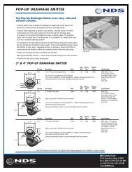
Pop-Up <strong>Drainage</strong> Emitter<br />
The pop-up emitter is opened by the hydrostatic pressure <strong>of</strong> water flowing through the<br />
drain pipe. As flow diminishes, the emitter closes again. The top <strong>of</strong> the emitter should<br />
be installed at a lower elevation that the invert <strong>of</strong> the pipe inlet (downspout<br />
connection, connection to a basin, etc.) to ensure proper flow. A 10’ length <strong>of</strong><br />
perforated pipe installed between the drain pipe and emitter will allow excess water in<br />
the drain pipe to leach into the soil.<br />
Pop-up Emitter<br />
Stormwater is discharged<br />
near the curb or to another<br />
safe area<br />
12 <strong>Principles</strong> <strong>of</strong> <strong>Exterior</strong> <strong>Drainage</strong> — <strong>Quick</strong> <strong>Review</strong>
C. <strong>Drainage</strong> Materials and Installations<br />
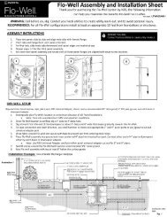
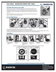
Flo-Well ® Leaching System<br />
The Flo-Well® allows water to be discharged directly into<br />
subsoil. This eliminates the need to install long runs <strong>of</strong><br />
pipe to conduct the water to a far-<strong>of</strong>f discharge point. The<br />
Flo-Well® disperses the water safely back into the subsoil<br />
within a safe area.<br />
Flo-Well ®<br />
For gutters and downspouts<br />
(far left)<br />
Install with sump pump<br />
(center)<br />
Eliminates puddles (right)<br />
4" PVC pipe<br />
Soil<br />
12" Sand<br />
Landscape Fabric<br />
NDS#FWFF67<br />
FLO-WELL ®<br />
NDS#FWAS24<br />
Sand<br />
2' dia.<br />
4' dia.<br />
4" PVC pipe<br />
Soil<br />
12" Gravel*<br />
FLO-WELL ®<br />
NDS#FWAS24<br />
Gravel*<br />
2' dia.<br />
4' dia.<br />
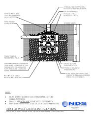
Flo-Well ® Installation<br />
Location and number <strong>of</strong><br />
ports removed will<br />
determine the rate and<br />
direction <strong>of</strong> leaching. Add<br />
gravel around outside <strong>of</strong><br />
Flo-Well ® unit to increase<br />
leaching capacity<br />
8" Minimum 8" Minimum<br />
*Class 2 Road Grade<br />
Flo-Well Installation Detail with Landscape<br />
Fabric Wrap in Sand Backfill<br />
Flo-Well Installation Detail in Gravel Backfill<br />
<strong>Principles</strong> <strong>of</strong> <strong>Exterior</strong> <strong>Drainage</strong> — <strong>Quick</strong> <strong>Review</strong> 13
14 <strong>Principles</strong> <strong>of</strong> <strong>Exterior</strong> <strong>Drainage</strong> — <strong>Quick</strong> <strong>Review</strong>
Fax completed quiz to 1-559-562-9488<br />
Attention Literature Dept.<br />
<strong>Principles</strong> <strong>of</strong> <strong>Exterior</strong> <strong>Drainage</strong> —<br />
<strong>Quick</strong> <strong>Review</strong> Quiz<br />
Please complete the following exam and return to NDS. A certificate <strong>of</strong> completion and an NDS hat will be<br />
sent to you for a 75% or higher score. Good Luck!<br />
Name:<br />
Company:<br />
Date:<br />
Company Address:<br />
City: State: Zip:<br />
Phone:<br />
Email:<br />
Matching<br />
1. Catch Basin<br />
2. Channel Drains<br />
3. French Drains<br />
4. Grates<br />
5. Gutter Downspout<br />
6. Atrium grate<br />
A. These are strainer covers that are installed on the top <strong>of</strong> a catch basin<br />
or drainage pipe<br />
B. Trench filled with coarse aggregate, and most commonly a<br />
perforated pipe, for intercepting and conveying ground water.<br />
C. This is the attachment that run vertically down the building in which<br />
the rain water is routed from the ro<strong>of</strong>-mounted gutters to grade level<br />
D. Structure with a grate on top used to collect and divert surface<br />
water to an underground drain pipe system.<br />
E. Ideal grate configuration for preventing cloggedd inlets due to<br />
leaves, mulch or debris in planters.<br />
F. Linear perimeter drain with a grate on top used to collect surface<br />
along flatwork or hardscapes, such as driveways, patios, parking<br />
lots, simming pools, etc.<br />
Multiple Choice<br />
7. When do you need a drainage system?<br />
❒ A. When your in-laws are coming to town<br />
❒ B. Everybody needs a drainage system<br />
❒ C. For excess ground water or surface runn<strong>of</strong>f<br />
❒ D. Never<br />
8. Which type <strong>of</strong> surface drainage system is ideal for<br />
hardscapes such as driveways, patios and swimming pools?<br />
❒<br />
❒<br />
❒<br />
❒<br />
A. French drains<br />
B. Channel drains<br />
C. Catch basins & grates<br />
D. Pump & hoses<br />
<strong>Principles</strong> <strong>of</strong> <strong>Exterior</strong> <strong>Drainage</strong> — <strong>Quick</strong> <strong>Review</strong> 15
POEDQRI<br />
Catalogs available from NDS:<br />
<strong>Drainage</strong> • Sloped Channel • Drip & Micro Irrigation • Landscape<br />
Fittings • Check Valves, Transition, Compression and Repair Couplings<br />
Equipment Pad • Meter Box • Valve Box • Landscape<br />
Oct2007<br />
• Catch Basins & Grates<br />
• Channel Drains<br />
• Flo-Well ® Stormwater<br />
Leaching Systems<br />
• Sewer & Drain Fittings<br />
• Backwater & Diverter Valves<br />
• Flexible Couplings<br />
• Flexible Saddles<br />
• Agrifim Drip Irrigation<br />
• Grass Pavers<br />
• Root Barriers<br />
• Valve & Meter Boxes<br />
• Equipment Pads<br />
• Flo Control Transition Fittings<br />
• Flo Control Check Valves<br />
• Flo Control Ball Valves<br />
• Flo Control Repair Couplings<br />
• Flo Control Saddles<br />
PARTIAL CLIENT LIST<br />
The White House<br />
Los Angeles Country Club<br />
Pebble Beach<br />
Cypress Point<br />
Spyglass Hill<br />
PGA West Stadium Golf Course<br />
Princeville Golf Course<br />
Ritz Carlton<br />
Santa Barbara Zoo<br />
Sheraton Hotels<br />
Sherwood Country Club<br />
Soldier Field<br />
Del Webb & Sun City Country Clubs<br />
Westin Hotels<br />
Riviera Country Club<br />
Buchart Gardens<br />
Disney World<br />
Disneyland<br />
Florida University<br />
Harbortown Golf Links<br />
Hyatt Grand Champions<br />
La Quinta Resort<br />
Marriott Hotels<br />
MGM Grand Hotel & Theme Park<br />
Mirage Hotel<br />
Jack La Lane Athletic Clubs<br />
Olympic Training Center<br />
Address/Telephone<br />
P.O. Box 339 • 851 N. Harvard Avenue<br />
Lindsay, CA 93247<br />
Phone: 800-726-1994<br />
Fax: 800-726-1998<br />
International Phone: 559-562-9888<br />
International Fax: 559-562-4488<br />
e-mail: nds@ndspro.com<br />
www.NDSPRO.com<br />
FOR TECHNICAL INFORMATION, CONTACT:<br />
Technical Services<br />
(888) 825-4716<br />
TechService@ndspro.com<br />
Regional Warehouses:<br />
• Lindsay, CA<br />
• Fresno, CA<br />
• Mineola, TX<br />
• Atlanta, GA<br />
• Seattle, WA<br />
• Philadelphia, PA<br />
• Puerto Rico