Tech Manual - Drainage Solutions, Inc.
Tech Manual - Drainage Solutions, Inc.
Tech Manual - Drainage Solutions, Inc.

You also want an ePaper? Increase the reach of your titles
YUMPU automatically turns print PDFs into web optimized ePapers that Google loves.
TECHNICAL<br />
SPECIFICATION<br />
GUIDE<br />
EXTERIOR DRAINAGE PRODUCTS<br />
NDS Customer Service<br />
851 N. Harvard Ave, Lindsay, CA 93247<br />
Phone: (800) 726-1994 • (559) 562-9888<br />
Fax: (800) 726-1998 • (559) 562-4488<br />
www.NDSPRO.com
TECHNICAL MANUAL<br />
EXTERIOR DRAINAGE PRODUCTS<br />
TABLE OF CONTENTS<br />
Overview.....................................................................................3<br />
Specifications .............................................................................4<br />
<strong>Tech</strong>nical Specifications ..............................................................4<br />
Catch Basins....................................................................4<br />
Grates...........................................................................4-5<br />
NDS 4" Channel ...............................................................5<br />
NDS 3" Channel ...............................................................5<br />
NDS 1 1 ⁄4" Channel..............................................................5<br />
Independent Laboratory Test Data.....................................5<br />
Physical & Chemical Properties ...................................................6<br />
Chemical Resistance...................................................................7<br />
NDS Chemical Resistance Guide...............................................7-9<br />
<strong>Drainage</strong> Guide..........................................................................10<br />
Catch Basins — Step-by-Step Installation ..................................13<br />
Adapters and Grates — Step-by-Step Installation .......................14<br />
Channel Drains — Preparing and Assembling Channel Drain .......15<br />
Preparing Site and Installation of Assembled Channel Drain .......16
Overview<br />
EXTERIOR DRAINAGE PRODUCTS<br />
NDS is the innovator of exterior surface drainage products. We offer a complete line of catch basins, grates,<br />
channel drains, and sewer and drain fittings. They are used to collect excess runoff water and dispense it into<br />
an underground drainage pipe. The drain pipe then discharges water to street curbs, storm water sewers,<br />
drainage ditches or other runoff areas. NDS products can be tied to an existing drain pipe or down spout connection<br />
as well.<br />
NDS drainage products are essential in maintaining healthy plant and lawn life, as well as protecting man-made<br />
structures from damage due to excess ground water. Locating low spots in landscaping, anticipating rainfall,<br />
and keeping in mind that water flows downhill are the keys to installing an effective drainage system.<br />
NDS products are designed to fit either corrugated pipe or sewer and drain pipe and fittings. Some of our<br />
grates, basins, and channel drains are load rated for light vehicular traffic. Our drainage systems are inexpensive,<br />
easy to install, light weight, and will not rust or need painting. Properly installed, they need little or no<br />
maintenance. NDS catch basins have a sump area that collects debris, preventing clogging of the pipeline.<br />
Grates are available in a variety of colors to blend in with surrounding surfaces. Depending on the size of the<br />
round, square, or atrium grates, they may fit directly into a riser of pipe, sewer and drain fitting, or our catch<br />
basins. (Refer to our catalog for the size of pipe, fittings or catch basin that each grate fits.) Popular applications<br />
for our grates include:<br />
TECHNICAL MANUAL<br />
• Round grates for landscaping<br />
• Square grates for brick, masonry, concrete, and asphalt applications<br />
• Atrium grates for landscaping, window wells or anywhere a flat grate may clog with debris such as<br />
leaves or mulch.<br />
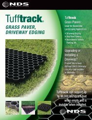
NDS offers three different size channel drain systems. They come complete with bottom and end outlets, couplings,<br />
end caps, fabricated elbows and tees. These systems solvent weld together like PVC pipe, using solvent<br />
glue for easy installation. The channel drains operate like a roof gutter, and are ideal for driveway, garage, patio,<br />
pool and landscape applications.<br />
NDS offers the most complete line of time-proven drainage products available for every drainage need. Their<br />
use is limited only by your imagination!<br />
• Landscaping • Irrigation • Foundations • Tennis Courts • Swimming Pools<br />
• Downspouts • Driveways • Stables • Dog Kennels • Rood Prone Areas<br />
• Slab Drains • Basements • Water Diversion Ditches • Garages • Marinas<br />
• Saunas and Spas • Patios • Hot Tubs • Nurseries and Hothouses<br />
• Golf Courses and much more!<br />
See Step-by-Step Installation guides on page 13.
TECHNICAL MANUAL<br />
EXTERIOR DRAINAGE PRODUCTS<br />
Specifications<br />
NDS quality one-piece molded parts conform to the following requirements. Use this data<br />
and NDS Specification data in your specifications to insure the highest quality.<br />
1. General: Catch basins, grates, channel drains, and valve boxes shall be one piece injection molded by NDS;<br />
they shall be uniform in quality, free from flashing, shrinkage, distortion, and other defects. Component parts<br />
shall fit together in a satisfactory manner.<br />
2. Quality: Material used in the manufacture of molded grates and valve boxes shall be structural foam<br />
polyethylene with ultra-violet light inhibitors. Material used in molded catch basins shall be polystyrene.<br />
Material used in extruded channel shall be polyvinyl chloride with ultra-violet light inhibitors.<br />
3. Open Surface Area: Grates deviation should not exceed +/- 5% of grate open surface areas designated in<br />
the NDS specifications catalog.<br />
4. Submittal: Manufacturer’s drawings shall be submitted to the architect/engineer for approval. The<br />
architect/engineer shall retain the right to reject parts not conforming to this specification and/or approved<br />
submittal drawings.<br />
5. Valve Box design: 6", 7” and 10" round sizes feature unique overlapping bayonet covers with finger holes.<br />
The 10" round and 12" x 17" rectangular designs include locking cover mechanism with optional bolt.<br />
<strong>Tech</strong>nical Specifications<br />
Catch Basins<br />
6" Round Basin (Spee-D Basin): Volume (nominal) 246 cu.in.<br />
Sump Area<br />
46 cu.in.<br />
9" x 9" Catch Basin: Volume (nominal) 669 cu .in.<br />
Sump Area<br />
70 cu.in.<br />
9" x 9" x 6" Riser add 647 cu.in.<br />
12" x 12" Square Catch Basin: Volume (nominal) 1328 cu.in.<br />
Sump Area<br />
244 cu.in.<br />
12" x 12" x 6" Riser add 1118 cu.in.<br />
18" x 18" Square Catch Basin: Volume (nominal) 6327 cu.in.<br />
Sump Area<br />
822 cu.in.<br />
Open Area for Flow Calculations (nominal): 3" & 4" Outlet (1243) 10.41 sq.in.<br />
3" & 4" Outlet (1244) 7.80 sq.in.<br />
6" Outlet (1266) 30.78 sq.in.<br />
8" Outlet (1888) 55.15 sq.in.<br />
Grates<br />
6" Round Grate Thickness .38 in.<br />
6" Atrium Grate Thickness .19 in.<br />
7" Square Grate Thickness 1.00 in.<br />
9" x 9" Square Grate Thickness 1.13 in.
EXTERIOR DRAINAGE PRODUCTS<br />
Grates (continued)<br />
12" x 12" Atrium Grate Thickness 1.38 in.<br />
18" x 18" Square Grate Thickness 1.13 in.<br />
NDS 4" Channel<br />
4" Wide Spee-D Channel Drain<br />
Channel Grate Dimensions: Thickness (nominal) .75 in.<br />
Slot Opening Size<br />
.38 in. x 3.63 in.<br />
Number of Slots/Grate 31<br />
Open Surface Area<br />
19.3 sq.in./ft.<br />
Channel Dimensions (nominal): Volume Cross Sectional Area' 8.18 sq.in.<br />
NDS 3" Channel<br />
2.75" Wide Mini Channel Drain<br />
Mini Channel Grate Dimensions: Thickness (nominal) 25 in.<br />
Slot Opening Size<br />
.25 in, x .88 in.<br />
Number of Slot/Grate 150<br />
Open Surface Area<br />
11.3 sq.in./ft.<br />
Mini Channel Dimensions (nominal): Volume Cross Sectional Area 7 sq.in.<br />
TECHNICAL MANUAL<br />
NDS 1¼" Channel<br />
1.25" Wide Micro Channel Drain<br />
Micro Channel Grate Dimensions: Thickness (nominal) .06 in.<br />
Slot Opening Size<br />
.19 in. x .63 in.<br />
Number of Slots/Grate 65<br />
Open Surface Area<br />
2.5 sq .in./ft.<br />
Micro Channel Dimensions (nominal): Volume Cross Sectional Area 2.75 sq.in.<br />
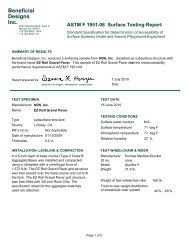
Independent Laboratory Test Data<br />
Load Ratings - NDS Grates<br />
We recommend these drains for light to medium duty capacities such as passenger cars and light<br />
truck areas only.<br />
SUMMARY OF COMPRESSION TEST RESULTS<br />
SAMPLE MATERIAL BRAND FORCE AT FAILURE COMPRESSION<br />
(PSI)<br />
(LBS.)<br />
3" Channel 500 series* NDS 206 9888<br />
4" Channel 400 series* NDS 272 13056<br />
9" X 9" Grate* NDS 327 15696<br />
12" X 12" Grate* NDS 275 13200<br />
18" X 18" Grate** NDS 88 4224
TECHNICAL MANUAL<br />
EXTERIOR DRAINAGE PRODUCTS<br />
* Method I: Load was applied via a 2.925" diameter x 3" long steel rod placed on the center distributing<br />
the load through the face of the steel rod. Test was performed in respective channels and basins to simulate<br />
field conditions.<br />
** Method II: Load was applied via an 8" diameter x .30" thick aluminum plate. Specimen was tested in a<br />
9.5" x 14" support frame made from 2" x 6" wood studs.<br />
Example: The 3" Channel 500 series is capable of withstanding a direct static loading force of at least<br />
206 PSI. Assuming a typical passenger car or light truck tire bearing upon a gross contact area of 48 square<br />
inches, this grate could theoretically support a static single wheel load of 9,888 lbs. in compression only.<br />
For a complete set of engineering test data & certification, please call NDS Customer Service at<br />
800-726-1994 or fax to 800-726-1998.<br />
Physical & Chemical Properties<br />
Composition:<br />
Polyethylene<br />
NDS Products:<br />
Grates - round, square, atrium, channel. Valve boxes.<br />
Tensile Strength:<br />
4500 psi (nominal)<br />
Melt Temperature: 130-137 degrees C.<br />
Flexural Modulus:<br />
180,000 psi (minimum)<br />
Notched Izod, Impact:<br />
5.0 ft- lbs/in.<br />
Hardness, Durometer Shore: 65<br />
Impact Strength (12 lbs wt., "B" tup min.): 6" Round Valve Box only 18 ft/lbs<br />
10" Round Valve Box only 45 ft/lbs<br />
14" Square Valve Box only 50ft/lbs<br />
Composition:<br />
PVC (Polyvinyl Chloride)<br />
NDS Products:<br />
Channel drains, Backwater valves, Sewer and drain fittings<br />
Tensile Strength:<br />
7000 psi (nominal)<br />
Melt Temperature: 75-105 degrees C.<br />
Composition:<br />
Styrene<br />
NDS Products:<br />
Basins, Risers, Universal outlets, Sump boxes and<br />
lids, Sewer and drain fittings<br />
Tensile Strength:<br />
3200 psi (nominal)<br />
Melt Temperature: 93-105 degrees C.<br />
Composition:<br />
ABS (Acrylonitrile Butadiene Styrene)<br />
NDS Products:<br />
Backwater valves, Sewer and drain fittings<br />
Tensile Strength:<br />
6800 psi (nominal)<br />
Melt Temperature: 11 0-125 degrees C.
Chemical Resistance<br />
EXTERIOR DRAINAGE PRODUCTS<br />
The following results were derived from testing using standard procedures including ASTM D543 “Standard<br />
Test Method for Resistance of Plastics to Chemical Reagents.” Actual results will vary for different applications<br />
depending on environmental conditions for each particular application and other modifying factors. The<br />
following table assumes ambient temperature of 75 degrees Fahrenheit.<br />
The comparative information presented considers the environmental and stress-cracking tendencies of the<br />
polymeric material. Sunlight can be destructive because of its ability to cleave main chain bonds of polymers.<br />
When specifying plastic products for outdoor use, include the requirement for NDS products with ultra-violet<br />
stabilizers to protect against deterioration and discoloration due to exposure to sunlight.<br />
NDS Chemical Resistance Guide<br />
NDS Plastic Materials Metals Rating Flo Control Gaskets<br />
@ max. Temp ( 0 F) or Rating<br />
@ max. Temp ( 0 F) or Rating<br />
Chemicals % ABS Polyolefin Polystyrene PVC Brass Cast Iron Ductile Iron EPDM Buna-n Viton<br />
TECHNICAL MANUAL<br />
Acetic Acid 25 - 180 A 73 C C C 180 C C<br />
Acetic Acid 50 - 140 A 73 C C C 140 C C<br />
Acetic Acid 80 - 100 B 73 C C C 100 C C<br />
Acetone - - 73 C C A A A 130 C C<br />
Aluminum Chloride Sat - 180 A 140 C C C 210 70 150<br />
Aluminum Fluoride Sat - - B 73 C C C 210 180 -<br />
Aluminum Sulfate Sat - 180 B 140 C C C 210 200 150<br />
Ammonium Acetate Sat - 73 B 140 C - - 140 - -<br />
Ammonium Chloride Sat - 180 A 140 C C C 210 180 A<br />
Ammonium Hydroxide 10 - 180 B 225 C 210 70 A<br />
Ammonium Sulfate - - 180 A 140 C B B 210 180 A<br />
Amyl Alcohol - - 180 A 100 A B B 210 140 A<br />
Barium Chloride Sat - 180 A 180 A B B 250 180 A<br />
Barium Hydroxide Sat - 180 - 140 A B B 250 180 A<br />
Benzene - - C C C A A A C C A<br />
Benzoic Acid All - 140 A 140 C C C C C -<br />
Borax Sat - 180 A 140 A A A 210 140 A<br />
Boric Aid Sat - 180 A 140 B B C 210 140 A<br />
Calcium Chloride - 100 180 A 140 B A A 210 100 A<br />
Calcium Hydroxide - - 180 - 140 C C C 210 140 A<br />
Carbon Tetrachloride - - C - 73 A C C C C A<br />
Chlorine Gas (Dry)ppm 150 C C B 120 C C C C C B<br />
Chlorinated Water ppm 3500 - C B C C - - C C B<br />
Chromic Acid 10 C 150 B 140 C C C 70 C B<br />
Chromic Acid 30 C 150 B 140 C C C C C -<br />
Chromic Acid 40 C 150 B 140 C C C C C -<br />
Chromic Acid 50 C C B 75 C C C C C -<br />
Citric Acid Sat - 180 A 140 C C C 210 70 A<br />
Copper Chloride Sat - - - 140 C C C 210 180 150<br />
Copper Cyanide - - - - 140 C C C 210 180 -<br />
Copper Nitrate 30 - - - 140 C C C 210 B to 70 -<br />
Copper Sulfate Sat - 120 A 140 C C C 210 180 150<br />
Creosote - - - - 73 B A A C 73 B<br />
Crude Oil - - - - 140 C C C C 70 -<br />
Dibutyl Ether - - - - - - - - C C C<br />
Diesel Fuel - - - - 140 A A A C 70 -<br />
Ethyl Alcohol - - 180 - 140 A A A 170 180 A
TECHNICAL MANUAL<br />
EXTERIOR DRAINAGE PRODUCTS<br />
NDS Chemical Resistance Guide<br />
NDS Plastic Materials Metals Rating Flo Control Gaskets<br />
@ max. Temp ( 0 F) or Rating<br />
@ max. Temp ( 0 F) or Rating<br />
Chemicals % ABS Polyolefin Polystyrene PVC Brass Cast Iron Ductile Iron EPDM Buna-n Viton<br />
Ethyl chloride Dry - 73 C C A A B to 70 C B<br />
Ethylene Glycol - - 120 A 140 A A A 210 180 A<br />
Ethyl Ether - - C - C - - - C C -<br />
Fatty Acids - - 120 - 140 C C C C 140 -<br />
Formic Acid - - 73 B 73 - C C 200 C C<br />
Fructose - - - - 140 - A A 175 140 -<br />
Gasoline(Leaded) - - C C C A A A C 70 A<br />
Gasoline(Unleaded) - - C C C A A A C 70 A<br />
Glycerine - - 180 A 140 A A A 200 70 A<br />
Hydrolic Oil - - - - 73 - A A C C -<br />
Hydrobromic Acid 20 - 120 - 140 C C C 140 C -<br />
Hydrobromic Acid 50 - - - 140 C C C 140 C -<br />
Hydrochloric Acid
EXTERIOR DRAINAGE PRODUCTS<br />
NDS Chemical Resistance Guide<br />
NDS Plastic Materials Metals Rating Flo Control Gaskets<br />
@ max. Temp ( 0 F) or Rating<br />
@ max. Temp ( 0 F) or Rating<br />
Chemicals % ABS Polyolefin Polystyrene PVC Brass Cast Iron Ductile Iron EPDM Buna-n Viton<br />
Silver Cyanide - - - - 140 C C C 140 C -<br />
Sodium Acetate Sat - 180 A 140 - B B 170 C -<br />
Sodium Bicarbonate - 70 180 - 140 B A A 250 180 A<br />
Sodium Borate Sat - 73 A - - B B 140 70 -<br />
Sodium Bromide Sat - 180 A 140 - C C 210 70 -<br />
Sodium Chloride - - 180 A 140 A B B 140 140 A<br />
Sodium Fluoride - - 185 A 140 - C C 140 70 -<br />
Sodium Hydroxide
TECHNICAL MANUAL<br />
EXTERIOR DRAINAGE PRODUCTS<br />
<strong>Drainage</strong> Guide<br />
How to calculate the pipe size and the appropriate NDS grate for exterior drainage applications.<br />
To guarantee a quality product, specify NDS grates by:<br />
• NDS Part Number<br />
• Polyethylene Grate with UV Inhibitors<br />
• Open Surface Area.<br />
Step 1: Calculate the total surface area to be drained (Feet length x Feet width).<br />
Step 2: Determine the coefficient of runoff for the type of soil (see chart below).<br />
Soil Texture Coefficient Soil Texture Coefficient<br />
of Runoff<br />
of Runoff<br />
Concrete or Asphalt 1.00 Loam - Bare .60<br />
Gravel- Compact .70 Loam - Light Vegetation .45<br />
Clay - Bare .75 Loam - Dense Vegetation .35<br />
Clay - Light Vegetation .60 Sand - Bare .50<br />
Clay - Dense Vegetation .50 Sand - Light Vegetation .40<br />
Gravel- Bare .65 Sand - Dense Vegetation .30<br />
Gravel- Light Vegetation .50 Grass Areas .35<br />
Gravel- Dense Vegetation .40<br />
NOTE: The above data is approximate. Coefficient of Runoff = Runoff / Rainfall.<br />
Step 3: Determine the maximum one hour rainfall expected in 100 years.<br />
100 Year Rainfall Map<br />
One Hour Rainfall<br />
in inches to be<br />
expected once in 100 years
EXTERIOR DRAINAGE PRODUCTS<br />
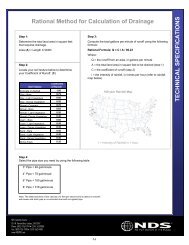
Step 4: Compute the total gallons per minute runoff using the following formula.<br />
Rational Formula: Q= CIA/96.23<br />
Where<br />
Q = the runoff from an area, in gallons per minute<br />
C = the coefficient of runoff (Step 2)<br />
I = the intensity of rainfall, in inches per hour (Step 3)<br />
A = the areas to be drained (Step 1)<br />
Step 5: Select the pipe size by using the following table.<br />
1 1/2" Pipe < 13 gal/minute 4" Pipe < 79 gal/minute<br />
2" Pipe < 21 gal/minute 6" Pipe < 180 gal/minute<br />
3" Pipe < 46 gal/minute 8" Pipe < 316 gal/minute<br />
TECHNICAL MANUAL<br />
Table assumes flow velocity of 2 feet per second.<br />
Step 6: Select the appropriate grate or combination of grates required. (See chart below)<br />
Area Grate Selection Chart<br />
Round, Square and Atrium Grates<br />
Capacity NDS Part Numbers Grate Fits Grate Open Surface<br />
GPM Green Black Gray Pipe Size Area (in 2 )<br />
3.4 16 14 15 3" 2.6<br />
4.5 01 02 03 3" 3.5<br />
5.0 13 11 12 4" 3.8<br />
5.6 07 08 09 4" 4.2<br />
12.0 50 40 60 6"* 9.1<br />
12.5 70 74 - 3" 9.5<br />
13.6 05 04 06 3.4" 10.4<br />
15.0 20 10 30 6"* 11.5<br />
17.8 772 771 773 6"* 13.6<br />
19.0 75 78 - 4" 14.5<br />
33.4 80 90 - 6"* 25.5<br />
37.2 950 970 960 6"* 28.4<br />
45.2 990 980 999 3, 4, 6" 34.4<br />
61.7 1212 1211 1210 3, 4, 6" 47.0<br />
78.7 1280 1290 - 3, 4, 6" 60.0<br />
136.5 1812 1811 1810 3, 4, 6, 8" 104.0<br />
*Use with Spee-D Basin
TECHNICAL MANUAL<br />
EXTERIOR DRAINAGE PRODUCTS<br />
Channel Grate Selection Chart<br />
Spee-D, Mini and Micro Channel<br />
Capacity NDS Part Numbers Outlet Fits Grate Open Surface<br />
GPM Various Colors Pipe Size Area (in 2 )<br />
25.2/ft 240, 241, 242, 243, 244, 251 3,4" 19.3/ ft<br />
14.7/ft 541, 542, 543, 544, 551 2" 11.3/ft<br />
2.6/ft 8001, 8002, 8003 1 1/2" 2.0/ft<br />
Example<br />
50' x 50' area, clay-light vegetation soil, Atlanta, GA<br />
Step 1: Surface area = 2,500 square feet.<br />
Step 2: Coefficient of runoff = .60<br />
Step 3: 1 hour maximum rainfall = 3.5 inches<br />
Step 4: Q = (2,500) (.60) (3.50) /96.23 = 55 gal/min<br />
Possibilities<br />
A) 4" or larger pipe used with either an NDS 1210, 1211, 1212 or larger grate.<br />
B) A multiple of smaller size pipe lines and/or grates which together achieve adequate flow in gallons per<br />
minute.<br />
NOTE: This is a reference chart only. For critical areas, consult a landscape architect or engineer.
EXTERIOR DRAINAGE PRODUCTS<br />
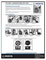
Catch Basins — Step-by-Step Installation<br />
Catch Basins are<br />
available in 4 sizes,<br />
with one to four<br />
outlets and connect<br />
to 3", 4", 6" or 8"<br />
sewer and drain or<br />
corrugated pipe.<br />
TECHNICAL MANUAL<br />
1. Locate low spot or any area where excess water<br />
will accumulate.<br />
2. Use Catch Basins in applications where it is necessary<br />
to collect debris from runoff water and later<br />
remove debris. This helps minimize clogging of<br />
drainage pipe. Choose basin size according to<br />
amount of runoff; it may be necessary to install<br />
more than one basin in succession to accommodate<br />
excessive runoff or a combination of low spots.<br />
Choose a larger basin with larger sump area for<br />
runoff containing debris, such as mulch or leaves.<br />
3. Dig hole deep enough for overall height of basin<br />
and grate, allowing for 1/4" recess of the grate below<br />
ground level. Install basin in hole on top of a firm<br />
base. Excavate the trench deep enough to accommodate<br />
drainage pipe and obtain proper slope.<br />
4. Connect pipe to basins, gradually sloping the<br />
pipe. Backfill trench and area around basin<br />
with dirt, sand, gravel, concrete or asphalt<br />
according to desired application.<br />
5. Finish off landscaping surrounding project area.<br />
DISCLAIMER: As conditions and methods of installation of our product are beyond our control, products contained herein are offered<br />
in good faith and subject to only our published warranty and guarantee. Claims for labor cost and other expenses required to replace<br />
defective products or repair of any damage resulting from the use thereof will not be allowed by NDS.
TECHNICAL MANUAL<br />
EXTERIOR DRAINAGE PRODUCTS<br />
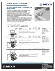
Adapters and Grates — Step-by-Step Installation<br />
Adapters and<br />
grates are available<br />
in many sizes and<br />
connect to 3", 4",<br />
6" or 8" sewer and<br />
drain pipe and fittings<br />
or corrugated<br />
pipe. They may be<br />
used with catch<br />
basins to complete<br />
a drainage system.<br />
1. Locate low spots or any area where excess water<br />
will accumulate.<br />
2. Use in areas where no sump area is needed or soil<br />
conditions are too difficult to dig deep enough to<br />
accommodate a catch basin. Choose adapter and<br />
or grates size according to amount of runoff. It<br />
may be necessary to install more than one adapter<br />
or grate in succession to accommodate excess<br />
runoff or a com bination of low spots.<br />
3. Dig hole for the adapter or fitting to be used with<br />
grate. Make hole deep enough for overall height<br />
of adapter, fitting and grate allowing for 1/4"<br />
recess of grate below ground level.<br />
4. Install adapter or fitting in hole on top of a firm<br />
base. Excavate a trench deep enough to accom -<br />
modate drainage pipe and obtain proper slope..<br />
Connect pipe to adapters or fittings gradually sloping<br />
pipe. Backfill pipe in trench and area around<br />
adapter or fitting with dirt, sand, gravel, concrete<br />
or asphalt according to desired application.<br />
5. Finish off landscaping surrounding area.<br />
DISCLAIMER: As conditions and methods of installation of our product are beyond our control, products contained herein are offered<br />
in good faith and subject to only our published warranty and guarantee. Claims for labor cost and other expenses required to replace<br />
defective products or repair of any damage resulting from the use thereof will not be allowed by NDS.
EXTERIOR DRAINAGE PRODUCTS<br />
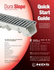
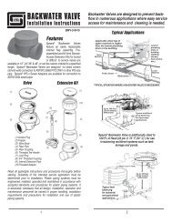
Channel Drains — Preparing and Assembling Channel Drain<br />
TECHNICAL MANUAL<br />
1. Locate lowest spot or any area where excess<br />
water will accumulate.<br />
2. Dig trench wide enough to allow for 2" of back fill<br />
on each side of Spee-D and Mini Channel, and 1"<br />
for Micro Channel. Dig trench deep enough for<br />
overall height of channel and grate, allowing for<br />
1/4" recess of grate below surface level, as well as<br />
1" of sand base underneath channel.<br />
3. Backfill trench with 1" of sand and tamp<br />
thoroughly. This allows for a level base and provides<br />
support. Trench bed must be compacted<br />
prior to installing channel.<br />
4. Measure and cut channel with fine tooth saw to<br />
desired length and remove burrs. Assemble channel,<br />
using couplings and channel accessories. Test<br />
for accurate measurements by placing channel in<br />
trench. (NOTE: Sewer and drain pipes.)<br />
5. Disassemble channel drain and apply PVC primer<br />
and PVC cement to all joints. Resemble channel<br />
joints. Allow cement to dry thoroughly.<br />
6. Install grate on channel. Completely cover grate<br />
with duct tape. (NOTE: Grate must be on channel<br />
prior to installation.)<br />
DISCLAIMER: As conditions and methods of installation of our product are beyond our control, products contained herein are offered<br />
in good faith and subject to only our published warranty and guarantee. Claims for labor cost and other expenses required to replace<br />
defective products or repair of any damage resulting from the use thereof will not be allowed by NDS.
TECHNICAL MANUAL<br />
EXTERIOR DRAINAGE PRODUCTS<br />
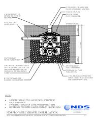
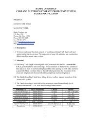
Preparing Site and Installation of Assembled Channel Drain<br />
1. Position assembled channel into trench with the<br />
grate recessed 1/4" below the ground level.<br />
2. Secure channel in trench using NDS stakes. See<br />
option 1 or option 2 in diagram C. Place stakes<br />
every 2 feet along both sides of channel. (NOTE:<br />
Use string line to ensure the channel is straight.)<br />
3. Back fill with either concrete, sand or dirt. Lightly<br />
tap down backfill with 2 x 4 to remove air and<br />
ensure that backfill has completely encased channel.<br />
(NOTE: All installations not using concrete<br />
backfill may now finish surface area and remove<br />
tape from grate. Installations using concrete backfill<br />
should complete Steps 4 through 7.)<br />
4. Smooth concrete surface.<br />
5. Use concrete edger and edge entire length of<br />
channel on both sides.<br />
6. Allow concrete to set for one hour or until it will<br />
firmly hold your thumb print. Use broom and<br />
brush concrete to give surface texture, if desired.<br />
7. Allow concrete to dry for five hours and then<br />
remove tape.<br />
Tools: Shovel, pick, hammer, hack saw, trowel,<br />
concrete edger.<br />
Materials: Duct tape, stakes, string, sand, PVC<br />
primer, PVC cement, and concrete.<br />
DISCLAIMER: As conditions and methods of installation of our product are beyond our control, products contained herein are offered<br />
in good faith and subject to only our published warranty and guarantee. Claims for labor cost and other expenses required to replace<br />
defective products or repair of any damage resulting from the use thereof will not be allowed by NDS.<br />
ARCHT<br />
NDS Customer Service<br />
851 N. Harvard Ave, Lindsay, CA 93247<br />
Phone: (800) 726-1994 • (559) 562-9888<br />
Fax: (800) 726-1998 • (559) 562-4488<br />
www.NDSPRO.com REV. 0408