The Resource Magazine For Apple, Atari, and Commodore ...
The Resource Magazine For Apple, Atari, and Commodore ...
The Resource Magazine For Apple, Atari, and Commodore ...

Create successful ePaper yourself
Turn your PDF publications into a flip-book with our unique Google optimized e-Paper software.
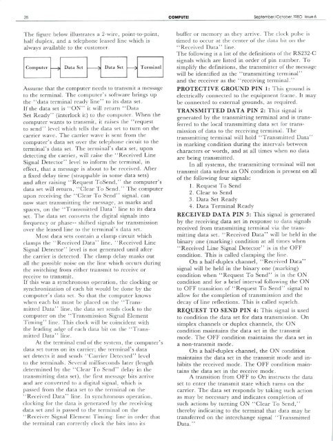
28 COMPUTE! September/Ociober. 198O. Issue 6<br />
<strong>The</strong> figure below illustrates a 2-wire, point-to-point,<br />
half duplex, <strong>and</strong> a telephone leased line which is<br />
always available to the customer.<br />
Computer Data Set Set Terminal<br />
Assume that the computer needs to transmit a message<br />
to the terminal. <strong>The</strong> computer's software brings up<br />
the "data terminal ready line" to its data set.<br />
If the data set is "ON" it will return "Data<br />
Set Ready" (interlock it) to the computer. When the<br />
computer wants to transmit, it raises the "request<br />
lo send" level which tells the data set to turn on the<br />
carrier wave. <strong>The</strong> carrier wave is sent from the<br />
computer's data set over the telephone circuit to the<br />
terminal's data set. <strong>The</strong> terminal's data set, upon<br />
detecting the carrier, will raise the "Received Line<br />
Signal Detector" level to inform the terminal, in<br />
effect, that a message is aboul to be received. After<br />
a fixed delay time (strappable in some data sets)<br />
<strong>and</strong> after raising "Request ToSend," the computer's<br />
data set will return. "Clear To Send." <strong>The</strong> computer<br />
upon receiving the "Clear To Send" signal, can<br />
now start transmitting the message, as marks <strong>and</strong><br />
spaces, on the "Transmitted Data" line to its data<br />
set. <strong>The</strong> data set converts the digital signals into<br />
frequency or phase-- shifted signals for transmission<br />
over the leased line to the terminal's data set.<br />
Most data sets contain a damp circuit which<br />
clamps the "Received Data" line. "Received Line<br />
Signal Detector" level is not generated until after<br />
the carrier is detected. <strong>The</strong> clamp delay masks out<br />
all [he possible noise on the line which occurs during<br />
the switching from either transmit to receive or<br />
receive to transmit.<br />
If this was a synchronous operation, the clocking or<br />
synchronization of each bit would be done by the<br />
computer's data set. So that the computer knows<br />
when each bit must be placed on the "Trans<br />
mitted Data" line, the data set sends clock to the<br />
computer on the "Transmission Signal Element<br />
Timing" line. This clock will be coincident with<br />
the leading adge of each data bit on the "Trans<br />
mitted Data" line.<br />
Ai the terminal end of the system, the computer's<br />
data set turns on its carrier; the terminal's data<br />
set detects it <strong>and</strong> sends "Carrier Detected" level<br />
to the terminals. Several milliseconds later (length<br />
determined by the "Clear To Sent!" delay in the<br />
transmitting data set), the first message bits arrive<br />
<strong>and</strong> are converted to a digital signal, which is<br />
passed from the data set to the terminal on the<br />
"Received Data" line. In synchronous operation,<br />
clocking for the data is generated by the receiving<br />
data set <strong>and</strong> is passed to the terminal on the<br />
"Receiver Signal Element Timing: line in order that<br />
the terminal can correctlv clock (he bits into its<br />
buffer or memory as they arrive. <strong>The</strong> clock pulse is<br />
timed to occur at the center of the data bit on the<br />
"Received Data" line.<br />
<strong>The</strong> following is a list of the definitions of the RS232-C<br />
signals which are listed in order of pin number. To<br />
simplify the definitions, the transmitter of the message<br />
will be identified as the "transmitting terminal"<br />
<strong>and</strong> the receiver as the "receiving terminal."<br />
PROTECTIVE GROUND PIN 1: This ground is<br />
electrically connected to the equipment frame. It may<br />
be connected to external grounds, as required.<br />
TRANSMITTED DATA PIN 2: This signal is<br />
generated by the transmitting terminal <strong>and</strong> is trans<br />
ferred to the local transmitting data set for trans<br />
mission of data to the receiving terminal. <strong>The</strong><br />
transmitting terminal will hold "Transmitted Data"<br />
in marking condition during the intervals between<br />
characters or words, <strong>and</strong> at all times when no data<br />
are being transmitted.<br />
In all systems, the transmitting terminal will not<br />
transmit data unless an ON condition is present on all<br />
of the following four signals:<br />
1. Request To Send<br />
2. Clear to Send<br />
3. Data Set Ready<br />
4. Data Terminal Ready<br />
RECEIVED DATA PIN 3: This signal is generated<br />
by the receiving data set in response lo data signals<br />
received from transmitting terminal via the trans<br />
mitting data set. "Received Data" will be held in the<br />
binary one (marking) condition at all times when<br />
"Received Line Signal Detector" is in the OFF<br />
condition. This is called clamping the line.<br />
On a half-duplex channel, "Received Data"<br />
signal will be held in the binary one (marking)<br />
condition when "Request To Send" is in the ON<br />
condition <strong>and</strong> for a brief interval following the ON<br />
to OFF transition of "Request To Send'' signal to<br />
allow for the completion of transmission <strong>and</strong> the<br />
decay of line reflections. This is called squelch.<br />
REQUEST TO SEND PIN 4: This signal is used<br />
to condition the data set for data transmission. On<br />
simplex channels or duplex channels, the ON<br />
condition maintains the data set in the transmit<br />
mode. <strong>The</strong> OFF condition maintains the data sei in<br />
a non-transmit mode.<br />
On a half-duplex channel, the ON condition<br />
maintains the data set in the transmit mode <strong>and</strong> in<br />
hibits the received mode. <strong>The</strong> OFF condition main<br />
tains the data set in the receive mode.<br />
A transition from OFF to On instructs the data<br />
set to enter the transmit state which turns on the<br />
carrier. <strong>The</strong> data set responds by taking such action<br />
as may be necessary <strong>and</strong> indicates completion of<br />
such actions by turning ON "Clear To Send,"<br />
thereby indicating to the terminal that data may be<br />
transferred on the interchange signal "Transmitted<br />
Data."