An Automatic Warping Points Extraction Method for Calibration of ...
An Automatic Warping Points Extraction Method for Calibration of ...
An Automatic Warping Points Extraction Method for Calibration of ...

Create successful ePaper yourself
Turn your PDF publications into a flip-book with our unique Google optimized e-Paper software.
<strong>An</strong> <strong>Automatic</strong> <strong>Warping</strong> <strong>Points</strong> <strong>Extraction</strong> <strong>Method</strong> <strong>for</strong><br />
<strong>Calibration</strong> <strong>of</strong> Wide <strong>An</strong>gle Camera<br />
Dae-Hyeon Kim, 1 Byung-Ik Kim, 1 Su-Young Ha, 1 Tae-Eun Shim, 2<br />
Young-Choon Kim, 3 and Kyu-Ik Sohng 1<br />
1 School <strong>of</strong> Electrical Engineering and Computer Science, Kyungpook National University, Korea<br />
2 Division <strong>of</strong> IT Cooperative Systems, Gyeongbuk Provincial College, Korea<br />
3 Dept. <strong>of</strong> In<strong>for</strong>mation and Communication Engineering, Youngdong University, Korea<br />
Abstract - Radial or pincushion distortion problem <strong>of</strong> the<br />
wide angle charge-coupled device (CCD) camera is an<br />
important issue in the image calibration in case <strong>of</strong> close-up<br />
photography <strong>of</strong> real scene. We designed the auto-extraction<br />
method <strong>of</strong> the warping points in the calibration algorithm <strong>of</strong><br />
the image acquired by the wide angle CCD camera. Proposed<br />
method extracts the distortion point by the wide angle CCD<br />
camera, using the threshold value <strong>of</strong> the histogram <strong>of</strong> the<br />
horizontal and vertical pixel lines. This processing step can be<br />
directly applied to the original image <strong>of</strong> the wide angle CCD<br />
camera output. Proposed method results are compared with<br />
hand-worked result image using the two wide angle CCD<br />
cameras having different angles (90° and 120°) with the<br />
difference value <strong>of</strong> the result images respectively.<br />
Experimental results show that proposed method can allocate<br />
the distortion-calibration constant <strong>of</strong> the wide angle CCD<br />
camera regardless <strong>of</strong> lens type, distortion shape and image<br />
type.<br />
When the picture is taken in occasion <strong>of</strong> camera with<br />
radial distortion, straight line in picture becomes <strong>for</strong>m <strong>of</strong><br />
curved line. The image pictured by the wide angle CCD<br />
camera seriously has such distortions. The representative<br />
algorithm <strong>of</strong> the image calibration is warping method.<br />
But warping algorithm has the several faults. <strong>Method</strong> has<br />
troublesome to find the points <strong>of</strong> the Fig. 4. (x i , y i ) and (x', y').<br />
We designed the auto-extraction algorithm <strong>of</strong> the extraction <strong>of</strong><br />
the warping points in the calibration algorithm <strong>of</strong> the CCD<br />
lens. Proposed method extract the warping points (x i , y i ) and<br />
(x', y') briefly and exactly. <strong>An</strong>d that is applied to camera<br />
lenses with various angles. [3]<br />
Keywords: image processing, image warping, auto<br />
calibration, lens distortion.<br />
1 Introduction<br />
The image generation <strong>of</strong> various cameras – like film or<br />
CCD cameras – are modeled with the pinhole camera<br />
model. [1] However, the images <strong>of</strong> real cameras suffer from<br />
more or less lens distortion, which is a nonlinear and<br />
generally radial distortion. [1] The first is due to the fact that<br />
many wide angle lenses have higher magnification in the<br />
image center than at the periphery. This causes the image<br />
edges to shrink around the center and <strong>for</strong>m a shape <strong>of</strong> a radial.<br />
The pincushion distortion is the inverse effect, when the<br />
edges are magnified stronger. [2] The original image, radial<br />
distortion image and pincushion distortion image are shown<br />
as Fig. 1.<br />
(a) (b) (c)<br />
Fig. 1. (a) The original grid, (b) radial distorted grid image<br />
and (c) pincushion distorted grid image.<br />
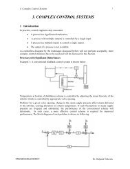
The organization <strong>of</strong> the paper is as follows. Section 2<br />
briefly introduces the basic warping algorithm <strong>for</strong> the image<br />
calibration as the previous work. In section 3, the proposed<br />
auto-extraction algorithm <strong>for</strong> the extraction <strong>of</strong> the warping<br />
point is described and the image calibration with the<br />
resolution preservation is explained. Section 4 gives the<br />
experimental result using proposed algorithm and the analysis.<br />
Conclusions are given in section 5.
2 A calibration method<br />
The warping algorithm <strong>for</strong> improvement <strong>of</strong> image<br />
distortion has been an essential algorithm in camera<br />
calibration until a recent date. This algorithm is a basic<br />
trans<strong>for</strong>mation that makes the spatial change <strong>of</strong> an image. The<br />
conventional warping algorithm <strong>for</strong> camera calibration is<br />
shown in Fig. 2. [4]<br />
Distorted<br />
image<br />
Distorted<br />
pattern image<br />
Extract crosspoints<br />
Calculate warping<br />
parameter<br />
<strong>Warping</strong><br />
Standard<br />
pattern image<br />
Calibrated<br />
image<br />
Fig. 2. The flow chart <strong>of</strong> the warping algorithm in camera<br />
calibration.<br />
At first, calculates the warping parameters (a i and b i )<br />
with the distorted pattern image and standard pattern image.<br />
Next, we can get the calibrated image by using the warping<br />
parameter. The warping equations can be expressed by the<br />
following Eq. (1), (2), and (3): [4],[5]<br />
The (X, Y) and (U, V) are the respective distortion points and<br />
standard points in Eq. (4):<br />
X =<br />
Y =<br />
U =<br />
V =<br />
T<br />
[ x1,<br />
x2,<br />
x3,<br />
L xn<br />
]<br />
T<br />
[ y1,<br />
y2,<br />
y3,<br />
L yn<br />
T<br />
[ u1,<br />
u2,<br />
u3,<br />
L un<br />
]<br />
[ v , v , v , L v ] T<br />
1<br />
2<br />
3<br />
n<br />
] (4)<br />
The warping parameters (a i and b i ) are calculated <strong>for</strong> the<br />
calibration <strong>of</strong> distorted image. It finds the (x i , y i ) and (u i , v i )<br />
points using the distorted and standard pattern images <strong>for</strong> the<br />
estimation <strong>of</strong> the warping parameters. The (x i , y i ) and (u i , v i )<br />
points are sample point <strong>of</strong> the distorted pattern image and<br />
standard pattern image respectively. Eq. (1), the warping<br />
parameters can be expressed by the following Eq. (5) <strong>for</strong> X:<br />
⎡ x1<br />
⎤ ⎡1<br />
⎢ ⎥ ⎢<br />
⎢<br />
x2<br />
⎥ = ⎢<br />
1<br />
⎢ M ⎥ ⎢M<br />
⎢ ⎥ ⎢<br />
⎣xn<br />
⎦ ⎣1<br />
u<br />
u<br />
M<br />
u<br />
1<br />
2<br />
n<br />
v1<br />
⎤<br />
⎥⎡a0<br />
⎤<br />
v2⎥⎢<br />
⎥<br />
a1<br />
M ⎥<br />
⎥⎢⎣<br />
a ⎥<br />
2<br />
v<br />
⎦<br />
n ⎦<br />
<strong>An</strong>d then Eq. (5) can be expressed by the following the Eq.<br />
(6).<br />
Where<br />
(5)<br />
X = PH<br />
(6)<br />
a<br />
1-order warping equation:<br />
X = a + a U + a V<br />
Y = b + bU + b V<br />
0<br />
0<br />
1<br />
1<br />
2<br />
2<br />
(1)<br />
⎡1<br />
⎢<br />
⎢<br />
1<br />
P =<br />
⎢M<br />
⎢<br />
⎣1<br />
u1<br />
v1<br />
⎤<br />
u<br />
⎥<br />
2<br />
v2<br />
⎥<br />
M M ⎥<br />
⎥<br />
u n<br />
v n ⎦<br />
(7)<br />
2-order warping equation:<br />
X<br />
Y =<br />
2 2<br />
= a0<br />
+ a1U<br />
+ a2V<br />
+ a3UV<br />
+ a4U<br />
+ a5V<br />
(2)<br />
2 2<br />
b0<br />
+ bU<br />
1<br />
+ b2V<br />
+ b3UV<br />
+ b4U<br />
+ b5V<br />
3-order warping equation:<br />
⎡a0<br />
⎤<br />
⎢ ⎥<br />
(8)<br />
H a<br />
=<br />
⎢<br />
a1<br />
⎥<br />
⎢⎣<br />
a ⎥<br />
2 ⎦<br />
The trans<strong>for</strong>mation matrix H a is expressed as Eq. (9):<br />
H<br />
a<br />
T −1<br />
T<br />
= ( P P)<br />
P X<br />
(9)<br />
X = a + a U + a V + a UV + a U<br />
0<br />
0<br />
6<br />
6<br />
1<br />
1<br />
2<br />
+ a U V + a UV<br />
Y = b + bU + b V + b UV + b U<br />
2<br />
+ b U V + b UV<br />
2<br />
7<br />
2<br />
7<br />
2<br />
2<br />
3<br />
3<br />
+ a U<br />
8<br />
8<br />
+ b U<br />
3<br />
3<br />
4<br />
4<br />
2<br />
9<br />
9<br />
2<br />
+ a V<br />
+ b V<br />
+ a V<br />
3<br />
3<br />
5<br />
5<br />
+ b V<br />
2<br />
2<br />
(3)<br />
By the same way, the trans<strong>for</strong>mation matrix H b <strong>for</strong> Y is<br />
expressed as Eq. (10):<br />
T −1<br />
T<br />
H = ( P P)<br />
P Y<br />
(10)<br />
b
However this algorithm has the several faults. That has<br />
problem needing to find the upper two points (x i , y i ) and (u i ,<br />
v i ). This means that it needs the pre-processing step finding<br />
the several points directly in standard pattern image. <strong>An</strong>d it<br />
also requires high computation time. There<strong>for</strong>e, we designed<br />
the auto-extraction method <strong>of</strong> the warping points in the<br />
warping algorithm.<br />
3 Proposed method<br />
In this paper, it extracts the distortion point by the wide<br />
angle CCD camera, using the threshold value <strong>of</strong> the histogram<br />
<strong>of</strong> the horizontal and vertical pixel lines. This processing step<br />
can be directly applied to the original image <strong>of</strong> the wide angle<br />
CCD camera output. The flow chart <strong>of</strong> the auto-extraction<br />
method <strong>of</strong> warping points is as following Fig. 3.<br />
It supposed that the lens and CCD is orthogonal. At first,<br />
it eliminates image’s noise and detects the edge <strong>of</strong> the image<br />
using the sobel filter in the acquired grid (pattern) image.<br />
Then, it per<strong>for</strong>ms the histogram algorithm <strong>for</strong> the all pixel line<br />
<strong>of</strong> the x-axis and y-axis. After the histogram process, it finds<br />
the pixel position (center point) having the maximum value <strong>of</strong><br />
the histogram. This center point represents the green point (x 0 ,<br />
y 0 ) in Fig. 4. Based on center point, the standard point is<br />
generated by using the threshold value <strong>of</strong> the respective<br />
histogram <strong>of</strong> the horizontal and vertical pixel line. The red<br />
triangle in Fig. 4 represents the standard points. The guide<br />
line is generated by using the vertical lines by the horizontal<br />
Acquisition <strong>of</strong> grid (pattern) image<br />
Noise elimination<br />
Edge detection<br />
<strong>Extraction</strong> <strong>of</strong> center point<br />
<strong>Extraction</strong> <strong>of</strong> cross-point in<br />
x-axis and y-axis center<br />
<strong>Extraction</strong> <strong>of</strong> all cross-point<br />
Fig. 3. The flow chart <strong>of</strong> the point extraction.<br />
Fig. 4. The detection result <strong>of</strong> the cross-point processed by<br />
auto-extraction method.<br />
standard points and horizontal lines by the vertical standard<br />
points. The intersection points <strong>of</strong> the guide line becomes (x i ',<br />
y i '). Next step is drawing the extraction area (with 11 × 11<br />
pixel size) based on the distance from the center point. The all<br />
cross-points are obtained by using Eq. (11) and (12). That is,<br />
the blue rectangular in Fig. 4 represents the extracted all<br />
cross-points (x i , y i ). The displacement value <strong>for</strong> the all crosspoints<br />
is calculated as the following Eq. (11) and (12):<br />
Δ x = S x − x + S y − y<br />
(11)<br />
i<br />
a<br />
'<br />
i<br />
'<br />
i<br />
0<br />
0<br />
b<br />
'<br />
i<br />
'<br />
i<br />
0<br />
Δ y = S x − x + S y − y<br />
(12)<br />
i<br />
c<br />
d<br />
The Δ xi<br />
and Δ yi<br />
are the pixel displacement value between<br />
(x i ', y i ') and (x i , y i ). These values are increased in proportion to<br />
the distance from the center point. The S a , S b , S c and S d<br />
represent the distortion constant. In Eq. (11) and (12), the<br />
value <strong>of</strong> Δ xi<br />
and Δ yi<br />
depend mainly on y i ' and x i '<br />
respectively. There<strong>for</strong>e these equations are simplified as<br />
following the Eq. (13) and (14):<br />
'<br />
i<br />
0<br />
0<br />
Δ x = S y − y<br />
(13)<br />
i<br />
b<br />
Δ y = S x − x<br />
(14)<br />
i<br />
c<br />
'<br />
i<br />
0<br />
The S b and S c are the dominant distortion constant related to<br />
the angle <strong>of</strong> the lens. The large angle <strong>of</strong> lens has the small S c<br />
and small angle <strong>of</strong> that has the large S c .
4 Experimental results<br />
Proposed method is applied to the gird (pattern) image<br />
<strong>for</strong> the experiment. <strong>An</strong>d the camera used in experiment is the<br />
two cameras with 90 and 120 degree. Fig. 5 and 6 shows the<br />
result image by proposed method. The extraction area and<br />
extraction points mentioned in section 3 are showed in Fig. 5.<br />
The green rectangular in Fig. 5 is acquired by Eq. (13)<br />
and (14) according to pixel distance from the center point (x 0 ,<br />
y 0 ). Finally, it extracts the extraction point by the intersection<br />
point <strong>of</strong> the maximum histogram value <strong>of</strong> the all horizontal<br />
and vertical directions in the green rectangular. We analyze S b<br />
and S c , the distortion constant. S b and S c have 334 and 226<br />
respectively in the camera with 90 degree. In case <strong>of</strong> the<br />
camera with 120 degree, S b and S d have 334 and 221<br />
respectively.<br />
A Fig. 6 and 7 show the (a) original grid (pattern) image<br />
(90° and 120°), (b) hand-worked result (90° and 120°), and<br />
(c) image by proposed method (90° and 120°) respectively.<br />
(a) (b) (c)<br />
Fig. 6. Experimental result images: (a) original grid (pattern)<br />
image (90°), (b) hand-worked image (90°), and (c) image by<br />
proposed method (90°).<br />
(a) (b) (c)<br />
Fig. 7. Experimental result images: (a) original grid (pattern)<br />
image (120°), (b) hand-worked image (120°), and (c) image<br />
by proposed method (120°).<br />
(a)<br />
(a) (b) (c)<br />
Fig. 8. Experimental result images: (a) real scene (90°), (b)<br />
hand-worked image (90°), and (c) image by proposed method<br />
(90°).<br />
(a) (b) (c)<br />
(b)<br />
Fig. 5. Extracted areas and points by proposed method: (a)<br />
extracted areas and points by 90° lens and (b) extracted areas<br />
and points by 120° lens.<br />
Fig. 9. Experimental result images: (a) real scene image<br />
(120°), (b) hand-worked image (120°), and (c) image by<br />
proposed method (120°).
The Fig. 8 and 9 respectively show (a) real scene image<br />
(90° and 120°), (b) hand-worked result (90° and 120°), and<br />
(c) image by proposed method (90° and 120°). For the<br />
application <strong>of</strong> real scene acquired by wide angle CCD camera,<br />
warping parameter (a i and b i ) calculated by using S b and S c<br />
are applied to real scene. Fig. 8 and 9 show that result image<br />
by proposed method is similar to hand-worked image by the<br />
naked eye.<br />
5 Conclusion<br />
We designed the auto-extraction algorithm <strong>of</strong> the<br />
extraction <strong>of</strong> the warping points in the calibration algorithm<br />
<strong>of</strong> the CCD lens. Proposed method extracts the warping point<br />
briefly and exactly. <strong>An</strong>d that is applied to camera lenses with<br />
various angles. <strong>An</strong>d then it extracts exactly the distorted point<br />
by the CCD lens. Experimental results show that proposed<br />
method can allocate the distortion-calibration constant <strong>of</strong> the<br />
CCD camera regardless <strong>of</strong> lens type, distortion shape and<br />
image type.<br />
6 References<br />
[1] C. Slama, "Manual <strong>of</strong> photogrammetry," American<br />
Society <strong>of</strong> Photogrammetry, Falls Church, VA, USA, 4th<br />
edition, 1980.<br />
[2] G. Vass and T. Perlaki, "Applying and removing lens<br />
distortion in post production," Second Hungrian<br />
Conference on Computer Graphics and Geometry, 2003.<br />
[3] B. Prescott and G. F. McLean, "Line-based correction <strong>of</strong><br />
radial lens distortion," Graphical Models and Image<br />
Processing, vol. 59, no. 1, pp. 39-47, Jan. 1997.<br />
[4] G. T. Han, K. J. Lee, Y. K. Kim, and W. Y. Kim,<br />
"Simplified auto calibration method <strong>for</strong> wide angle CCD<br />
lens," The Collection <strong>of</strong> 1998 Autumn Conference's<br />
Paper <strong>of</strong> Korea In<strong>for</strong>mation Processing Society, October<br />
1999.<br />
[5] I. N. Junejo, X. Cao and H. Foroosh, "Autoconfiguration<br />
<strong>of</strong> a dynamic nonoverlapping camera network," IEEE<br />
Transactions on Systems, vol. 37, no. 4, pp. 803-816,<br />
Aug. 2007.