Turret Drilling and Tapping Machine - MIS Group, Inc.
Turret Drilling and Tapping Machine - MIS Group, Inc.
Turret Drilling and Tapping Machine - MIS Group, Inc.

You also want an ePaper? Increase the reach of your titles
YUMPU automatically turns print PDFs into web optimized ePapers that Google loves.
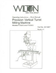
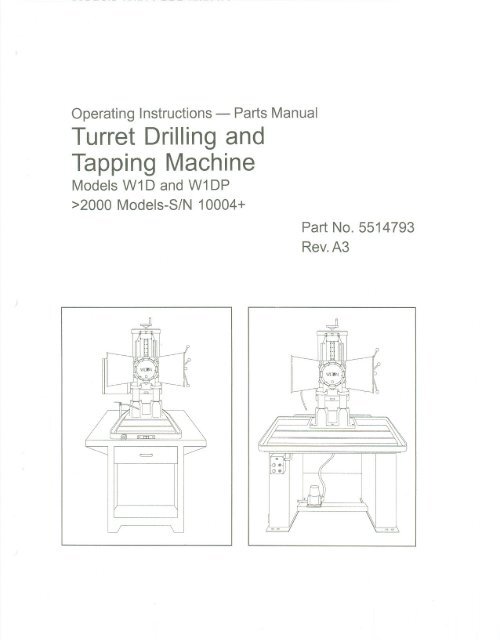
Operating Instructions -<br />
<strong>Turret</strong> <strong>Drilling</strong> <strong>and</strong><br />
<strong>Tapping</strong> <strong>Machine</strong><br />
Models W10 <strong>and</strong> W1DP<br />
>2000 Models-SIN 10004+<br />
Parts Manual<br />
Part No. 5514793<br />
Rev.A3<br />
=
Table of Contents<br />
Cover Page.. 0...0 00.000,...0..."""""" 0 0..""""""""" 00","".0""",..0 00."""""""""'" 0""'" 1<br />
General Specifications 0"""""'"'''''''''''''''''''''''''''''''''''''''''''''''''''''''''''''''''''''''''''''''''''''''''''' 4<br />
Operating Precautions<br />
Introduction 0...0 0 0"<br />
5<br />
7<br />
0.."""'" 0 0..0 0 ',""" 0 0 000 ',"""""'"<br />
Set-up <strong>and</strong> Installation "0"""'"'''''''''''''''''''''' 9<br />
Maintenance 0 """'''''''''''''''''''''''''''''''''''''''''''''''''''''''''''''''''''''''''''''''''''''' 0""'" 13<br />
T rou bleshooting ... .. .... .. ... .... ... ....... .... . .... .. ... ... .... .... .... .. . .... ...,. ..... ... ... .... .. .... .... 16<br />
ReplacementParts 18<br />
3
General Specifications<br />
The bench Model W 1D is an accurate <strong>and</strong><br />
productive 6 spindle turret drilling <strong>and</strong> tapping<br />
machine. The Model W1 D has the capacity for<br />
drilling Jt2-inchholes in mild steel, <strong>and</strong> 5/8-inch<br />
holes in cast iron. It is ideally suited to most<br />
manual <strong>and</strong> short batch production jobs. This<br />
machine has ground, dove-tail slide ways, that<br />
are protected by way wipers. The machine has<br />
accurately ground adjustable depth stops that<br />
assure depth accuracy of:t 0.002 inch.<br />
The Wilton Model W1 DP turret drilling <strong>and</strong><br />
tapping machine has a 24-inch by 40-inch<br />
"<br />
production table. The model W1 DP has the<br />
OG><br />
same features as the popular W1 D-series. As a<br />
OG><br />
production machine, the W1 DP offers one of<br />
the largest table in its size <strong>and</strong> range capabilities.<br />
The T-slotted surface permits the use of<br />
rotary indexers, shuttle tables <strong>and</strong> other modern<br />
production fixturing. Model W1 DP is available in<br />
either manual or power feed models.<br />
Specifications<br />
ModelNumber W1D W1DP<br />
Type Bench Mount ProductionTable<br />
<strong>Drilling</strong> Capacity:<br />
Mild Steel 1/2-lnch 1/2-lnch<br />
Cast Iron 5/8-lnch 5/8-lnch<br />
Tap Capacity (Mild Steel) 1/2-lnch 1/2-lnch<br />
SprindleNose 5/8-16 5/8-16<br />
SprindleStroke 5.90 <strong>Inc</strong>hes 5.90 <strong>Inc</strong>hes<br />
SprindleSpeeds 12 (275 - 4010) 12 (275 - 4010) .<br />
Pre-selective(4 per spindle, 3 ranges) Preselective(4 per spindle in 3 ranges)<br />
High range #1- #4 4010, 2005,1355,675 4010,2005,1355,675<br />
Mediumranve #2-#5 2550,1275,860,430 2550, 1275,860,430<br />
Low range #3-#6 1630, 815, 550, 275 1630,815,550,275<br />
OptionalLow Range 510,255, 170,85 510,255, 170,85<br />
Power Feed NotAvailable ExtraCost Option<br />
Dimensions:<br />
<strong>Machine</strong> 34W x 47D x 46H <strong>Inc</strong>hes 34W x 47D x 78H <strong>Inc</strong>hes<br />
Spindleto Table 21.65 <strong>Inc</strong>hesMaximum 24 <strong>Inc</strong>hes Maximum<br />
7-3/8 <strong>Inc</strong>hes Minimum 9-3/4 <strong>Inc</strong>hes Minimum<br />
Column to SpindleCenter 8-1/2-lnches<br />
8-1/2-lnches<br />
Base to SpindleCenter 7.95-lnches 7.95-lnches<br />
Table; Working Surface ... 17 x 12 <strong>Inc</strong>hes<br />
40 x 18 <strong>Inc</strong>hes<br />
Table:Overall 20-1/2 <strong>Inc</strong>hes 46 x 30 <strong>Inc</strong>hes<br />
CoolantTrough 1-314<strong>Inc</strong>hes 3 <strong>Inc</strong>hes<br />
T-Slots None 1/2-lnch<br />
Motor<br />
2 speed, 1HP,3-Phase, 1500/3000rpm... 2 speed, 1HP,3-Phase, 1500/3000rpm<br />
Magneticstarter,thermal overload,24 V Magneticstarter,thermal overload,24<br />
V<br />
at the switch with EmergencyStop at the switch with Emergency Stop<br />
DepthControl Pre-selectivespindlescrew stops Pre-selectivespindle screwstops<br />
Shipping Weight (w/o Base).. 840 Pounds<br />
NotApplicable<br />
Shipping Weight (w/Base) 940 Pounds 1,650Pounds<br />
4
- Misuse of this machine can cause serious injury.<br />
- For safety, machine must be set up, used <strong>and</strong><br />
serviced properly.<br />
- Read, underst<strong>and</strong> <strong>and</strong> follow instructions in the<br />
Operating Instructions <strong>and</strong> Parts Manual which<br />
was shipped with your machine.<br />
When setting up machine:<br />
- Always avoid using machine in damp or poorly<br />
lighted work areas.<br />
- Always be sure the machine support is securely<br />
anchored to the floor or the work bench.<br />
When using machine:<br />
- Always wear safetyglasses with side shields (See<br />
ANSI Z87.1)<br />
- Neverwear loose clothing orjewelry.<br />
- Never overreach-you may slip <strong>and</strong> fall.<br />
When servicing machine:<br />
- Alwaysdisconnecthe machinefromitselectrical<br />
supply while servicing.<br />
- Always follow instructions in Operating Instructions<br />
<strong>and</strong> Parts Manual when changing accessory tools<br />
or parts.<br />
- Never modify the machine without consulting<br />
Wilton Corporation.<br />
You-the stationary power tool userhold<br />
the key to safety.<br />
Read <strong>and</strong> follow these simple rules for best results<br />
<strong>and</strong> full benefits from your machine. Used properly,<br />
Wilton's machinery is among the best in design <strong>and</strong><br />
safety. However, any machine used improperly can<br />
be rendered inefficient <strong>and</strong> unsafe. It is absolutely<br />
m<strong>and</strong>atory that those who use our products be<br />
properly trained in how to use them correctly. They<br />
should read <strong>and</strong> underst<strong>and</strong> the Operating Instructions<br />
<strong>and</strong> Parts Manual as well as all labels affixed to<br />
the machine. Failure in following all of these warnings<br />
can cause serious injuries.<br />
<strong>Machine</strong>ry General Safety Warnings<br />
1. Always wear protective eye wear when operating<br />
machinery. Eye wear shall be impact resistant,<br />
protective safety glasses with side shields which<br />
comply with ANSI Z87.1 specifications. Use of<br />
eye wear which does not comply with ANSI Z87.1<br />
specifications could result in severe injury from<br />
breakage of eye protection.<br />
2. Wear proper apparel. No loose clothing or<br />
jewelry which can get caught in moving parts.<br />
Rubber soled footwear is recommended for best<br />
footing.<br />
3. Do not overreach. Failure to maintain proper<br />
working position can cause you to fall into the<br />
machine or cause your clothing to get caught -<br />
pulling you into the machine.<br />
4. Keep guards in place <strong>and</strong> in proper working<br />
order. Do not operate the machine with guards<br />
removed.<br />
5. Avoid dangerous working environments. Do not<br />
use stationary machine tools in wet or damp<br />
locations. Keep work areas clean <strong>and</strong> well lit.<br />
6. Avoid accidental starts by being sure the start<br />
switch is "OFF" before plugging in the machine.<br />
7. Never leave the machine running while unattended.<br />
<strong>Machine</strong> shall be shut off whenever it is<br />
not in operation.<br />
8. Disconnect electrical power before servicing.<br />
Whenever changing accessories or general<br />
maintenance is done on the machine, electrical<br />
power to the machine must be disconnected<br />
before work is done.<br />
9. Maintain all machine tools with care. Follow all<br />
maintenance instructions for lubricating <strong>and</strong> the<br />
changing of accessories. No attempt shall be<br />
made to modify or have makeshift repairs done to<br />
the machine. This not only voids the warranty but<br />
also renders the machine unsafe.<br />
10. <strong>Machine</strong>ry must be anchored to the floor.<br />
11. Secure work. Use clamps or a vise to hold work,<br />
when practical. It is safer than using your h<strong>and</strong>s<br />
<strong>and</strong> it frees both h<strong>and</strong>s to operate the machine.<br />
12. Never brush away chips while the machine is in<br />
operation.<br />
13. Keep work area clean. Cluttered areas invite<br />
accidents.<br />
14. Remove adjusting keys <strong>and</strong> wrenches before<br />
turning machine on.<br />
15. Use the right tool. Don't force a tool or attachment<br />
to do a job it was not designed for.<br />
16. Use only recommended accessories <strong>and</strong> follow<br />
manufacturers instructions pertaining to them.<br />
17. Keep h<strong>and</strong>s in sight <strong>and</strong> clear of all moving parts<br />
<strong>and</strong> cutting surfaces.<br />
18. All visitors should be kept at a safe distance from<br />
the work area. Make workshop completely safe<br />
byusingpadlocks,masterswitches,or by<br />
removing starter keys.<br />
19. Know the tool you are using - its application,<br />
limitations, <strong>and</strong> potential hazards.<br />
5
General Electrical Cautions<br />
This saw should be grounded in accordance with<br />
the National Electrical Code <strong>and</strong> local codes <strong>and</strong><br />
ordinances. This work should be done by a qualified<br />
electrician. The saw should be grounded to<br />
protect the user from electrical shock.<br />
Wire sizes<br />
Caution: for circuits which are far away from the<br />
electrical service box, the wire size must be increased<br />
in order to deliver ample voltage to the motor.<br />
To minimize power losses <strong>and</strong> to prevent motor<br />
overheating <strong>and</strong> burnout, the use of wire sizes for<br />
branch circuits or electrical extension cords according<br />
to the following table is recommended.<br />
AWG (Americanwire gauge) number<br />
Conductor length 240volt lines 120volt lines<br />
0-50 feet NO.14 NO.14<br />
50-100feet NO.14 NO.12<br />
Over 100 feet NO.12 No. 8<br />
Safety Instructions for Drill Presses<br />
1. All work shall be secured using either clamps or a<br />
.vise to the drill press table. It is unsafe to use your<br />
h<strong>and</strong>s to hold any workpiece being drilled.<br />
2. Drill press head <strong>and</strong> table shall be securely locked<br />
to the column before operating the drill press. This<br />
must always be checked prior to starting the machine.<br />
3. Always use the correct tooling. Tooling shall<br />
always be maintained <strong>and</strong> properly sharpened. All<br />
tooling must be run at the proper speeds <strong>and</strong> feeds<br />
as they apply to the job. Use only recommended<br />
accessories <strong>and</strong> follow those manufacturers instructions<br />
pertaining to them. Tooling shall be not be<br />
forced in to any workpiece but fed according to the<br />
proper specifications. Failure to follow these instructions<br />
will not only ruin the tooling as well as the<br />
machine, but can cause serious injury.<br />
4. Never brush awayany chips while the machine is<br />
in operation. All clean up should be done when the<br />
machine is stopped.<br />
5. Keep h<strong>and</strong>s in sight. Do not put h<strong>and</strong>s or fingers<br />
around, on, or below any rotating cutting tools.<br />
Leather safety gloves should be used when h<strong>and</strong>ling<br />
any sharp objects or cutting tools. See Figure A.<br />
6. Always wear protective eye wear when operating,<br />
servicing or adjusting machinery. Eyewear shall be<br />
impact resistant,protectivesafety glasseswith side<br />
shields complyingwith ANSI Z87.1 specifications.<br />
Use of the eye wear which does not comply with<br />
ANSI Z87.1 specifications could result in severe<br />
injury from breakage of eye protection. See Figure<br />
B.<br />
7. When drilling in material which causes dust, a<br />
dust mask shall be worn. See Figure C.<br />
8. Avoid contact with coolant, especially guarding the<br />
eyes.<br />
9. Non-slipfootwear <strong>and</strong> safety shoes are recommended.<br />
See Figure D.<br />
10. Wear ear protectors (plugs or muffs) during<br />
extended periods of operation. See Figure E.<br />
6<br />
A<br />
B<br />
C D E<br />
8<br />
:.::=.-.:; '".~<br />
'.". '-:-<br />
"'00<br />
::\;"~".;.
Introduction<br />
This manual includes operating <strong>and</strong> maintenance<br />
instructions for the Wilton Model W1 D-series <strong>and</strong><br />
W1 DP-series <strong>Turret</strong> Drill <strong>and</strong> <strong>Tapping</strong> <strong>Machine</strong>. This<br />
manual also includes parts listings <strong>and</strong> illustrations of<br />
replaceable parts.<br />
<strong>Machine</strong> Features<br />
Figures 1 <strong>and</strong> 2 depict the main features of the W1 DP<br />
<strong>Turret</strong> Drill <strong>and</strong> <strong>Tapping</strong> <strong>Machine</strong>.<br />
Tool Guard<br />
(both sides)<br />
Coolant Valve<br />
<strong>and</strong> FlexTube<br />
Electrical<br />
Enclosure<br />
On/Off<br />
Switch<br />
Pump<br />
Switch<br />
Coolant<br />
Gauge<br />
Coolant Reservoir<br />
LJ<br />
Coolant Pump<br />
Slide<br />
Indexing<br />
Figure 1: <strong>Machine</strong> Features<br />
(Model W1 DP-series)<br />
Housing<br />
Bar<br />
Feed H<strong>and</strong>le<br />
<strong>Turret</strong><br />
Spindles<br />
Support Column<br />
The Model W1 D-series <strong>Turret</strong> Drill <strong>and</strong> <strong>Tapping</strong><br />
<strong>Machine</strong> is configured for placement on a bench. It<br />
can also be mounted on an optional floor st<strong>and</strong> with<br />
coolant system.<br />
Work<br />
Table<br />
The W1 DP-series <strong>Turret</strong> Drill <strong>and</strong> <strong>Tapping</strong> <strong>Machine</strong> is<br />
a production table version of the basic W 1D-series<br />
machine.<br />
The slide housing supports a hexagon-shaped<br />
indexing bar. The indexing bar has adjustable depth<br />
stops mounted on all six sides of the bar; one stop for<br />
each spindle. The stops are adjusted to control the<br />
depth of the hole being drilled.<br />
A speed control drum is mounted on the top of the<br />
slide housing. The speed control drum has a speed<br />
selection knob for each turret spindle. The knobs are<br />
marked "H" (for high motor speed) <strong>and</strong> "L" (for low<br />
motor speed). These knobs allow you to pre-select<br />
the speed required for each spindle.<br />
Guards are provided on both sides of the turret to<br />
protect the operator from injury by the tools when the<br />
turret indexes to the next position.<br />
A feed h<strong>and</strong>le is provided on the right side of the<br />
machine. The feed h<strong>and</strong>le is fitted with a coiled flat<br />
spring that helps to return the slide to the up position.<br />
A switch box is provided at the left front of the table.<br />
The box contains the emergency shutoff <strong>and</strong> ON/OFF<br />
switches.<br />
The W 1D <strong>and</strong> W 1DP have a coolant reservoir that is<br />
internal to the base of the machine. The coolant flow<br />
control valve <strong>and</strong> flex tube are installed at the left rear<br />
of the machine.<br />
The machine drive motor is located at the back of the<br />
slide housing. The motor is fitted with two pulleys to<br />
enable the machine to be set up to operate at different<br />
speeds.<br />
A pulleycover is removedto gain a'ccessto the drive<br />
belt. The drive motor pulleysare connected to<br />
machine drive pulleys by a V-belt. The V-belt is<br />
placed on the innermostor outermost motor <strong>and</strong> the<br />
drive pulleysto obtain the requiredspindle speeds<br />
(refer to the Operationsection for speed change<br />
procedures).<br />
7<br />
The turret head is mounted on the slide housing of the<br />
machine. The slide housing is mounted on two<br />
vertical columns. The slide housing is positioned on<br />
the columns using a threaded rod that is attached to<br />
the upper column support housing.
<strong>Turret</strong> Tripper Screw<br />
Junction Box<br />
; MotorPulleys<br />
(2)<br />
V-Belt<br />
Drive<br />
Pulleys<br />
(2)<br />
Belt Tensioning Lever<br />
Figure 2: Key Features (Rear view<br />
with pulley cover removed)<br />
A belt-tensioning lever is provided to make it easy<br />
to replace the V-belt or to reposition the V-belt to<br />
change spindle speeds.<br />
A turret indexing switch (refer to Figure 3) is<br />
mounted on the top of the slide housing. The<br />
switch has a roller-type follower that follows a<br />
machined ramp on the main machine housing.<br />
The follower enters the ramp when the slide<br />
housing is approximately o/..-inchfrom its upper<br />
most travel limit. When the follower nears the<br />
bottom of the ramp, the switch actuates, causing<br />
the turret to index to the next spindle location.<br />
The switch can be adjusted using the jam nut on<br />
the barrel of the switch plunger.<br />
Slide Housing<br />
Machinist's<br />
Cam Ramp<br />
8<br />
Jam Nut<br />
Figure 3: <strong>Turret</strong> Indexing Switch
Set-up <strong>and</strong> Installation<br />
Mounting<br />
The machine legs have mounting holes that can be<br />
used to secure the machine to the floor. It is recommended<br />
that the machine be anchored to the floor for<br />
safe operation.<br />
Freeing-up Drill Head<br />
Drill head travel during shipment is restrained by one of<br />
the depth stops on the indexing bar. To free-up the drill<br />
head, proceed as follows:<br />
1. Remove the cap screw retaining the stop bracket.<br />
2. Temporarily install the bracket at the top of the<br />
indexing column. The drill head should be free to<br />
move.<br />
3. Reposition the bracket as required during setup of<br />
the first work piece. Secure with the cap screw.<br />
Electrical Connection<br />
Refer to the Wiring Diagram section for wiring<br />
information. Connection to electrical power should<br />
be made by a qualified electrician. Observe local<br />
electrical codes when connectingthe machine.<br />
Adjusting Position of Slide Housing<br />
The slide housing may be raised or lowered to<br />
accommodate the height of the work piece <strong>and</strong>/or the<br />
length of the drill or tapping adapter.<br />
To change position, loosen the two clamping bolts on<br />
the main machine housing. Then rotate the hex<br />
adjuster as required to raise of lower the slide<br />
housing (refer to Figure 4).<br />
Hex Adjuster<br />
Installation of Drive Belt<br />
The machine is shipped without the drive belt installed.<br />
The drive belt will need to be installed on the pulley<br />
pairs that will provide the spindle speed required. To<br />
install the belt, proceed as follows:<br />
1. Loosen two cap screws securing the belt cover.<br />
2. Remove the belt from the tools package provided<br />
with the machine.<br />
3. Refer to the Operation section to determine the<br />
pulley pairs that should be used to obtain the desired<br />
speed.<br />
4. Install the cover <strong>and</strong> secure with two cap screws.<br />
Make sure the electrical interlock switch is closed<br />
when the cover is installed.<br />
9<br />
Coolant System (W1D-Series)<br />
Connect the coolant system to the W 1D-series<br />
machine as follows:<br />
1. Place the work table on the machine base.<br />
2. Connect the coolant supply <strong>and</strong> drain tube to the<br />
fittings on the underside of the work table.<br />
3. Wire the coolant pump to the M5 contactor in the<br />
electrical enclosure. An access hole may need to<br />
to be made in the electrical enclosure.<br />
4. Fill the reservoir with the required coolant.<br />
Clamping Bolts (2)<br />
Figure 4: Raising/Lowering Slide Housing
Spindle Setup<br />
CAUTION: MAKE SURE THE CHUCK MOUNTING<br />
FACE AND SPINDLE SHOULDER ARE FREE OF<br />
DIRT AND DEBRIS IN ORDER TO ASSURE ACCU-<br />
RATE MACHINING.<br />
1. Determine the sequence in which you wish to<br />
mount the cutting tools on the turret head. The<br />
sequence should consider not only the operations<br />
to be performed; it should also consider the<br />
spindle speeds available at each station.<br />
2. Keep the overhang of all tools as equal as possible<br />
to eliminate lost motion required to bring the<br />
tools to the work. (Use spindle extensions to equalize<br />
tool length; extensions are available in 1-inch, 2-<br />
inch, <strong>and</strong> 3-inch lengths).<br />
3. Mount cutting tools in proper sequence in the<br />
chucks, sleeves, tapping heads, etc. (refer toFigure<br />
5).<br />
an unused station. A short downward <strong>and</strong> upward<br />
stroke of feed h<strong>and</strong>le will allow turret to index to next<br />
station.<br />
7. Set the depth for each spindle by adjusting stop<br />
blocks for each spindle. Use the scale on right of<br />
column for rough setting. Remove the cap screw from<br />
the stop block. Move the stop block to the position<br />
on the indexing bar that comes closest to the desired<br />
depth stop location. Make final adjustments by<br />
loosening the knurled nut <strong>and</strong> turning the depth stop<br />
screw until it contacts the stop bar. Install <strong>and</strong><br />
tighten the cap screw.<br />
WARNING: MAKE SURE THE TIP OF THE TOOLS<br />
DO NOT EXTEND MORE THAN 13 INCHES FROM<br />
THE CENTER OF THE TURRET TO AVOID INJURY<br />
OR DAMAGE TO THE CUTTING TOOL.<br />
Maximum distance from center of turret to tip of tool<br />
should not exceed 13 inches to assure safe clearance<br />
within the guards (refer to CAUTION plate in Figure 6).<br />
0 a<br />
CAUTION<br />
DO NOT FEED SPINDLE DCNVNWARD<br />
WI-IILE TURRET IS INDEXING<br />
~<br />
TOOL SHOULD NOT EXTEND C1\IER<br />
13" FROM CENTER OF TURRET TO<br />
TIP OF DRILL<br />
0<br />
Figure 6: CAUTION Plate<br />
0<br />
@<br />
NOTE: Do not feed a spindle dow(lward while the<br />
turret is indexing.<br />
Figure 5: <strong>Turret</strong> with<br />
Spindle<br />
Adapters<br />
<strong>and</strong> Extensions<br />
4. Set turret headto convenientworkingclearance<br />
over the work by raising or loweringthe main housing<br />
on columns Loosenclamping bolts <strong>and</strong> raise or lower<br />
by turning hex adjuster at top of columns. When<br />
proper height is reached, tighten the clamping bolts.<br />
5. Operate the machine through working cycle. Set<br />
the depth stop screw at each positionto suit the<br />
work. The turret will index automaticallywhen slide<br />
housing is raised to its upper travel limit. To repeat<br />
operations at one spindle without indexing,simply<br />
avoidraisingtheslideto the upperlimit.<br />
6. To skip a station, or stations, first adjust depth<br />
stop screw down to shortest stroke to prevent feeding<br />
A - Cleaning: At time of shipment, all exposed,<br />
machined surfaces are coated with a rust preventative.<br />
Before moving either the slide or the body these<br />
surfaces should be thoroughly cleaned to remove the<br />
rust preventative. This is extremely important since it<br />
prevents any dirt <strong>and</strong> grit that may have accumulated<br />
on the rust preventative from working under the sliding<br />
members <strong>and</strong> causing undue wear. Mount feed<br />
h<strong>and</strong>les <strong>and</strong> spindle guard, as per drawing.<br />
B - Bring leads to terminals R, S, T, in electrical<br />
panel.<br />
C - Once power is brought to the machine, DO NOT<br />
INDEX THE TURRET UNTIL YOU HAVE CHECKED<br />
DIRECTION OF ROTATION OF THE MOTOR. The<br />
red arrow on belt guard indicates correct direction of<br />
rotation. To test rotationof spindle, quicklyjog ON<br />
<strong>and</strong> OFF switch at front of table. Spindle should<br />
rotate in clockwise direction.<br />
10
OperatingInstructions<br />
Controls<br />
Model W 1DP has the start, stop <strong>and</strong> pump switches<br />
mounted in a switch box at the left front of the<br />
machine.<br />
The switches on Model W 1D are in the center of the<br />
work table. The E-stop is to the left of the on/off<br />
switches.<br />
There are two selector switches on the door of the<br />
electrical enclosure on the left side of the machine.<br />
The upper switch is a two-position switch that is used<br />
to change motor speed from high speed to low speed.<br />
The second switch is the coolant pump on/off switch.<br />
two-step "V" belt drive (refer to Figure 9).<br />
CAUTION: THE HI/La SPEEDTOGGLE SWITCH<br />
MUST BE SET IN THE."HI" POSITION FOR HIGH<br />
PULLEY SETUP AND "La" POSITION FOR LOW<br />
PULLEY SETUP.<br />
H (high)/L (low)<br />
knobs<br />
Spindle Speed<br />
Chart<br />
Setting Spindle Speeds<br />
There are six H/L (High/Low) knurled knobs in the<br />
housing at the top of the indexing column (refer to<br />
Figure 7). These knobs are used to set high (H) or<br />
low (L) speeds required at each tool station on the<br />
tu rret.<br />
Refer to the spindle speed chart in Figure 8. The<br />
chart shows the speeds that are available at each<br />
turret station spindles<br />
The spindle speed of the machine is set up in two<br />
ranges: high <strong>and</strong> low. The machine uses a two-step,<br />
V-belt drive located at rear of machine. There are<br />
two drive ranges that provide two speeds for each<br />
spindle is available through the use of a two-speed<br />
motor.<br />
Spindle speed changes are accomplished<br />
as follows:<br />
1. A high <strong>and</strong> a low speed range is provided by a<br />
--.<br />
Depth Stops<br />
Depth Scale<br />
Indexing Bar<br />
Figure 7: High/Low Spindle Speed Setting<br />
Knobs<br />
2. Set the HI/La speed selector switch in the<br />
position required by the position of the V-belt. Put<br />
SPINDLE SPEED CHART<br />
KNOB<br />
SPiNDLEI POSITION 11<br />
Figure 8: Spindle Speed Chart
the switch in the HI position for a high speed pulley<br />
set up. Put the switch in the La position for a low<br />
speed pulley set up. (Refer to the CAUTION plate<br />
in Figure 10).<br />
3. To change the speed range, remove the belt<br />
cover at rear of the machine. Loosen the clamping<br />
screw (see <strong>Turret</strong> Orive Components, Replacement<br />
Parts section). Turn the belt tension lever to<br />
loosen the V-belt. Place the belt in the High or Low<br />
speed pulleys as required. Turn belt tension lever to<br />
tighten the belt. Tighten the clamping screw.<br />
4. Use the H/L knobs on the speed control drum at<br />
the top of slide housing to pre-select the speed for<br />
each spindle (see speed control chart in Figure 8).<br />
5. If set incorrectly, the turret indexing speed will<br />
be too rapid or too slow. The machine is designed<br />
to index the turret head at a pre-set speed. The<br />
indexing speed designed into the machine has<br />
been selected to provide for maximum machine life<br />
<strong>and</strong> production output.<br />
6. If you find that the turret head indexes too fast<br />
or too slow, it may be <strong>and</strong> indication that either 1)<br />
the indexing micro-switch is not operating correctly,<br />
or 2) the HI/La toggle switch is in the wrong<br />
position.<br />
0 CAUTION 0<br />
WHEN BELT IS ON<br />
"HI" PULLEY<br />
WHEN BELT IS ON<br />
"LON' PULLEY<br />
~ rfJ<br />
TOGGLE SVIIITCH MUST TOGGLE SWITCH MUST<br />
BE IN "H" POSIllON I BE IN "LON' POSIllON<br />
INCORRECT SETllNG<br />
OF TOGGLE SVIIITCH<br />
0 MAY RESUL7 IN DAMPGE TO MACHNE 0<br />
Figure 10: CAUTION Plate (Belt Position<br />
vs. "HI/LOW" Switch Position)<br />
"HI" Speed<br />
Setup<br />
"LO" Speed Setup<br />
12<br />
\~l<br />
j~--~A--;,<br />
Figure 9: Belt-to-PulleySetup (for "HI/LO" Speed Operation)
Maintenance<br />
Lubrication<br />
The turret head <strong>and</strong> gearbox are filled with a highgrade<br />
gear oil (Mobil compound 0-0 or equivalent)<br />
before the machine is shipped from the factory. The<br />
turret head <strong>and</strong> gearbox are filled to the proper level on<br />
the oil gage. A common oil supply lubricates both the<br />
turret head <strong>and</strong> the gearbox.<br />
1. Shut off the drive motor.<br />
2. Disconnect electrical power.<br />
3. Move the slide housing to its lowest position to<br />
expose the bearing adjustment nut.<br />
4. Tighten lock nut.<br />
Adjustment of Feed H<strong>and</strong>le Spring<br />
Tripper Screw<br />
Check the oil level with spindle NO.2 in operating<br />
position. The oil level on the turret oil gage should be<br />
at level marked in red.<br />
The machine drive shaft is equipped with greasesealed<br />
universal joints. Check periodically for grease<br />
leaks through the boot on the universal joint. Replace<br />
the universal joint if leakage is noted. If not replaced,<br />
the universal joints will wear out very quickly.<br />
After the machine has been in operation approximately<br />
30 days, drain oil from the turret head <strong>and</strong><br />
gearbox <strong>and</strong> refill to proper level with correct grade<br />
machine oil.<br />
Drain plugs are provided at bottom of gearbox, <strong>and</strong> on<br />
perimeter of turret head. The fill hole is located<br />
between spindles No's, 4 <strong>and</strong> 5 on the perimeter of<br />
turret head.<br />
<strong>Machine</strong><br />
Front<br />
Tripper<br />
Plunger<br />
NOTE: The turret <strong>and</strong> gearbox are filled with KLUBER<br />
type Lamora 320, Vg. 320 oil, at the factory.<br />
Cleaning<br />
Chips generated by drilling an tapping should be<br />
periodically removed during operation of the machine.<br />
Chips <strong>and</strong> other machining debris should be removed<br />
upon completion of the machining operation <strong>and</strong><br />
whenever the machine is not being used.<br />
Adjustment of Safety Clutch<br />
After the drill <strong>and</strong> tap machine has been in used for<br />
sometime, the turret head may index sluggishly, or<br />
does not index completely. Check to make sure there<br />
is no binding of the turret head. If there is no binding,<br />
it may be necessary to tighten the safety clutch.<br />
WARNING: DISCONNECT ELECTRICAL POWER<br />
TO THE MACHINE BEFORE PERFORMING ANY<br />
MAINTENANCE.<br />
Tighten the clutch as follows (refer to Figure 11):<br />
Figure 11: Cutaway View<br />
of Tripper Mechanism<br />
WARNING: DISCONNECT ELECTRICAL POWER<br />
TO THE MACHINE BEFORE PERFORMING ANY<br />
MAINTENANCE.<br />
<strong>Inc</strong>reasing Spring Force<br />
<strong>Inc</strong>rease or decrease spring force as follows (refer to<br />
Figure 11):<br />
1. Disconnect electrical power.<br />
2. Remove safety screw on face of slide.<br />
3. Lower slide until rack is out of engagement using<br />
the feed h<strong>and</strong>le.<br />
CAUTION: BE SURE TO HOLD THE FEED<br />
HANDLE TO PREVENT RAPID UNWINDING OF<br />
THE SPRING. IF NOT HELD, THE SPRING<br />
COULD BREAK OR CAUSE INJURY TO MAINTE-<br />
NANCE PERSONNEL.<br />
13
4. Turn feed shaft counterclockwise to increase<br />
tension on the spring. Turn the feed shaft clockwise<br />
to decrease springtension.<br />
CAUTION: ONE-HALF REVOLUTION OF SHAFT<br />
WILL MAKE CONSIDERABLE DIFFERENCE IN<br />
SPRING TENSION AND COUNTERWEIGHT<br />
ACTION.<br />
5. When the springforce is as desired, install the<br />
safety screw.<br />
Replacing Feed H<strong>and</strong>le Spring<br />
1. Disconnect electrical power.<br />
2. Lower the slide housing until rack is out of<br />
engagement with feed h<strong>and</strong>le pinion gear.<br />
CAUTION: ONE-HALF REVOLUTION OF SHAFT<br />
WILL MAKE CONSIDERABLE DIFFERENCE IN<br />
SPRING TENSION AND COUNTERWEIGHT<br />
ACTION.<br />
3. Remove (3) cap screws, <strong>and</strong> pull feed h<strong>and</strong>le<br />
assembly out of column assembly.<br />
4. Remove pin <strong>and</strong> disengage collar from feed shaft.<br />
5. Slide feed shaft out of housing.<br />
WARNING: MAKE SURE TO USE A HEAVY<br />
CLOTH TO CONTAIN THE SPRING WHEN<br />
REMOVING THE SPRING FROM THE HOUSING.<br />
FAILURE TO DO SO CAN RESULT IN INJURY<br />
WHEN THE SPRING UNWINDS.<br />
6. Place a heavy cloth (such as burlap) over the<br />
spring housing <strong>and</strong> pull the broken spring out of the<br />
housing. (The cloth protects personnel from injury<br />
as spring unwinds).<br />
7. Insert new spring into housing. Make sure that<br />
"hook" on outside coil of the spring engages the pin.<br />
When the spring is wound, the feed shaft turns<br />
counter-clockwise, so be sure spring is inserted into<br />
housing correctly (refer to Feed H<strong>and</strong>le Assembly,<br />
Replacement Parts section).<br />
WARNING: REMOVE "KEEPERS" AROUND<br />
SPRING ONLY AS THE SPRING IS INSERTED<br />
INTO THE HOUSING. IF ALL THE KEEPERS<br />
ARE REMOVED, THE SPRING CAN UNEXPECT-<br />
EDLY UNWIND CAUSING INJURY.<br />
8. Install the feed shaft <strong>and</strong> engage the inner "hook"<br />
of the spring on the shaft pin.<br />
9. Mount feed collar <strong>and</strong> install pin through the<br />
collar <strong>and</strong> shaft.<br />
10. Before engaging the pinion <strong>and</strong> rack wind the<br />
spring by turning feed h<strong>and</strong>le counterclockwise.<br />
Turn the feed h<strong>and</strong>le until spring feels tight enough.<br />
CAUTION: DO NOT LET GO OF FEED WHEEL AS<br />
IT WILL ALLOW SPRING TO UNWIND AND<br />
BREAK.<br />
11. Engage the rack <strong>and</strong> pinion by moving the slide<br />
housing upward. Install three cap screws to secure<br />
feed h<strong>and</strong>le housing.<br />
12. Install the safety screw in the face of the slide<br />
housing.<br />
Replacement of Drive Motor Belt<br />
WARNING: DISCONNECT ELECTRICAL POWER<br />
TO THE MACHINE BEFORE PERFORMING ANY<br />
MAINTENANCE.<br />
1. Disconnect electrical power.<br />
2. Loosen the cap screws on both sides of the pulley<br />
cover.<br />
3. Loosen the clamping screw (see <strong>Turret</strong> Drive<br />
Components, Replacement Parts section).<br />
4. Turn the belt tension lever to loosen the V-belt.<br />
Remove the V-belt.<br />
5. Place the replacement V-belt in the High or Low<br />
speed pulleys as required.<br />
6. Turn belt tension lever to tighten the belt. Tighten<br />
the clamping screw.<br />
Replacement of Motor<br />
WARNING: DISCONNECT ELECTRICAL POWER<br />
TO THE MACHINE BEFORE PERFORMING ANY<br />
MAINTENANCE.<br />
1. Disconnect electrical power.<br />
2. Remove pulley cover <strong>and</strong> remove the drive motor<br />
belt (see Replacing the Drive Motor Belt).<br />
3. Disconnect electrical wiring from motor junction<br />
box.<br />
4. Remove motor attaching screws <strong>and</strong> washers.<br />
Remove the drive motor.<br />
5. Remove the screw <strong>and</strong> washer from the motor<br />
shaft. Remove pulley <strong>and</strong> key from the motor shaft.<br />
6. Install the key <strong>and</strong> pulley on the replacement<br />
motor. Secure pulley with the screw <strong>and</strong> washer.<br />
7. Install the motor on the main housing. Install four<br />
motor attaching screws <strong>and</strong> washers.<br />
8. Reinstall the drive belt <strong>and</strong> secure the cover with<br />
two cap screws (see Replacing the Drive Motor Belt).<br />
9. Connect electrical wiring to drive motor (refer to<br />
Wiring Data).<br />
10. Connect electrical power. Start the machine <strong>and</strong><br />
check operation of the drive motor.<br />
14
Disassembly of <strong>Turret</strong> Head<br />
WARNING: DISCONNECT ELECTRICAL POWER<br />
TO THE MACHINE BEFORE PERFORMING ANY<br />
MAINTENANCE.<br />
1. Disconnect electrical power.<br />
2. Remove plate from front of turret.<br />
3. Remove lock nut from stud shaft.<br />
4. Remove the spring washer <strong>and</strong> thrust bearing.<br />
5. Remove the turret from slide housing.<br />
6. Remove <strong>and</strong> discard oil seal.<br />
7. Remove <strong>and</strong> discard retaining ring.<br />
8. Using a puller, tap out spindle assembly.<br />
9. Press in new spindle assembly <strong>and</strong> secure with a<br />
new retaining ring.<br />
10. Tap in mating clutch. Make sure the gears mesh<br />
properly wh ile pressing.<br />
11. Install a new oil seal.<br />
12. Install the turret over the stud shaft. Install thrust<br />
bearing, spring washer <strong>and</strong> lock nut.<br />
13. Check the operation of the turret. If the turret over<br />
or under indexes, or if the turret indexes faster or<br />
slower than normal, refer to the Troubleshooting<br />
section.<br />
Replacement of Universal Joints<br />
The machine drive shaft is equipped with greasesealed<br />
universal joints. Because of the capacity of<br />
the universal joints <strong>and</strong> the sealed-in lubricant,<br />
replacement <strong>and</strong> lubrication should not be required. If<br />
the drive shaft or universal joints require replacement,<br />
remove according to the following procedures.<br />
Removing Innermost Universal Joint<br />
1. Move the slide housing to its uppermost position.<br />
WARNING: DISCONNECT ELECTRICAL POWER<br />
TO THE MACHINE BEFORE PERFORMING ANY<br />
MAINTENANCE.<br />
NOTE: When replacing universal joints, it is very<br />
important that the locating dots on the universal<br />
joints aligned. If not, considerable noise <strong>and</strong><br />
excessive wear will result.<br />
8. Installend of shaft in its mating shaft. Install key<br />
in shaft <strong>and</strong> install universal on the shaft. Tighten the<br />
set screw.<br />
Removing Outermost Universal Joint<br />
1. Move the slide housing to its uppermost position.<br />
WARNING: DISCONNECT ELECTRICAL POWER<br />
TO THE MACHINE BEFORE PERFORMING ANY<br />
MAINTENANCE.<br />
2. Shut off motor <strong>and</strong> disconnect electrical power.<br />
3. Remove pulley cover <strong>and</strong> remove the drive motor<br />
belt (see Replacing the Drive Motor Belt).<br />
4. Remove the drive shaft pulley.<br />
5. Remove retaining ring (on inner face of bearing<br />
block) securing bearing block. Pull the assembled<br />
bearing block, universal joint, <strong>and</strong> shaft from the main<br />
housing.<br />
6. Slide the boot down the shaft to uncover the<br />
universal joint. Drive the pins out of the universal joint.<br />
Separate universal joint from both shafts.<br />
7. Install the replacement universal joint on the shaft<br />
<strong>and</strong> secure with the pins.<br />
NOTE: When replacing universal joints, it is very<br />
important that the locating dots on the universal<br />
joints aligned. If not, considerable noise <strong>and</strong><br />
excessive wear will result.<br />
8. Slip boot over universal joint.<br />
9. Install end of shaft in its mating shaft.<br />
10. Install the bearing block <strong>and</strong> secure with the<br />
retaining ring.<br />
11. Install the drive shaft key <strong>and</strong> pulley. Secure with<br />
screw <strong>and</strong> washer.<br />
15<br />
2. Shut off motor <strong>and</strong> disconnect electrical power.<br />
3. Loosen set screw on innermost universal joint.<br />
Pull the innermost universal joint from the shaft.<br />
4. Remove the key from the shaft.<br />
5. Separate the shaft from its mating shaft.<br />
6. Slide the boot down the shaft to uncover the<br />
universal joint. Drive the pin out of the universal joint.<br />
Separate universal joint from the shaft.<br />
7. Install the replacement universal joint on the shaft<br />
<strong>and</strong> secure with the pin.
Troubleshooting<br />
Fault Probable Cause Remedy<br />
<strong>Turret</strong> does not index. <strong>Turret</strong> head loose. 1. Remove plate from front ofturret<br />
by removing three screws.<br />
2. If turret head is over indexing,<br />
tighten turret stud nut one-quarter<br />
turn at a time until corrected.<br />
3. If turret is under indexing, loosen<br />
turret stud nut one-quarter turn at a<br />
time until corrected.<br />
4. If turret is too tight turret will fail<br />
to complete index; check adjust<br />
ment carefully.<br />
<strong>Turret</strong> does not fully index <strong>Turret</strong> stud nut too loose or 1. Remove plate from front of turret<br />
(over or under indexes). too tight. by removing three screws.<br />
.<br />
The machineis properly 2. Ifturret head is over indexing,<br />
set at the factory <strong>and</strong><br />
tightenturret stud nut one-quarter<br />
pinned in position. The<br />
turn at a time until corrected.<br />
indexingmechanism is<br />
designedto accurately<br />
3. Ifturret is under indexing, loosen<br />
move the turret to the<br />
turret stud nut one-quarterturn at a<br />
next positionwithout<br />
time until corrected.<br />
overor undertravel.<br />
4. If turret is too tight turret will fail<br />
.<br />
The mechanism initially to complete index; check adjust<br />
indexesthe turret head<br />
ment carefully.<br />
to an approximate position.<br />
A tapered pin then<br />
locates the turret head in<br />
its final position.<br />
. When properly set, the<br />
turret will have a very<br />
slight clockwise movement<br />
at the end of the<br />
index cycle (due to the<br />
locating pin action in the<br />
tapered bushing).<br />
16<br />
Unbalanced tooling in turret.<br />
Rearrange turret tooling.<br />
(The turret will over index as the<br />
heaviest station travels downward<br />
<strong>and</strong> will under index as it is being<br />
carried upwards.)
Troubleshooting,cont.<br />
Fault Probable Cause Remedy<br />
<strong>Turret</strong> leaking oil. Loose nut on stud shaft. 1. Remove plate from front of turret<br />
by removing three screws.<br />
2. If turret head is over indexing,<br />
tighten turret stud nut one-quarter<br />
turn at a time until corrected.<br />
3. If turret is under indexing, loosen<br />
turret stud nut one-quarter turn at a<br />
time until corrected.<br />
4. If turret is too tight turret will fail to<br />
complete index; check adjustment<br />
carefully.<br />
17
Replacement Parts<br />
This section provides exploded view illustrations that show the replacement parts for the Wilton Model<br />
W 1D-series <strong>and</strong> Model W 1DP-series <strong>Turret</strong> <strong>Drilling</strong> <strong>and</strong> <strong>Tapping</strong> <strong>Machine</strong>. Also provided are parts<br />
listings that provide part number <strong>and</strong> description. The item numbers shown on the illustration relate to<br />
the item numbers in the facing parts listing.<br />
Order replacement parts from:<br />
Wilton Corporation<br />
300 South Hicks Road<br />
Palatine, IL 60067<br />
TEL: 1-888-594-5866<br />
FAX: 1-800-626-9676<br />
Identify the replacement part by the part number shown in the parts listing. Be sure to include the model<br />
number <strong>and</strong> serial number of your machine when ordering replacement parts to assure that you will<br />
receive the correct part.<br />
18
Assembled View.. ExternalComponents<br />
4<br />
5<br />
1<br />
2<br />
3<br />
35<br />
Model: W1D<br />
7,8<br />
6<br />
9<br />
10<br />
=<br />
29<br />
11,12<br />
14<br />
13<br />
33<br />
34<br />
31,32<br />
1<br />
2<br />
30<br />
4<br />
3<br />
35<br />
14,13<br />
15<br />
16<br />
Detail: Upper Rear<br />
19<br />
17<br />
18,19<br />
20,21<br />
22<br />
23<br />
24---1<br />
Model: W1 DP
Parts List -<br />
External Components<br />
Ref.<br />
No. Part No. Description Qty.<br />
1 5514810 H<strong>and</strong>le 1<br />
2 5514811 H<strong>and</strong>wheel 1<br />
3 5514815 Guard,Tool, (Right) 1<br />
4 5514833 Guard,Tool(Left) 1<br />
5 5514848 Enclosure, Electrical 1<br />
5514850 EnclosureW/Components(Complete)<br />
6 5514822 Pump,Coolant 1<br />
7 5514832 Valve,Shut-off,Coolant 1<br />
8 5514831 Nozzle,Coolant,Flexible 1<br />
9 5514817 Table,Work 1<br />
10 5514828 Switch, E-Stop 1<br />
11 5514826 Switch, On 1<br />
12 5514813 Switch, Off 1<br />
13 5514819 Base,Table 1<br />
14 5514814 Drawer, Base (W/Pull) 1<br />
15 5514820 Enclosure, Electrical 1<br />
5514821 EnclosureW/Components (Complete) 1<br />
16 5514816 Base,Column 1<br />
17 5514824 Light, Indicator 1<br />
18 5514846 Switch, High/Low(Speed) 1<br />
19 5514847 Switch, On/Off (Coolant) 1<br />
20 5514825 Switch, On (Green) 1<br />
21 5514827 Switch, Off (Red) 1<br />
22 5514823 Pump,Coolant 1<br />
23 5514818 Base/Table 1<br />
24 5514829 Gauge, Fluid,Coolant 1<br />
25 5514860 Switch, Limit 1<br />
26 5514861 Screw,Pan Head 2<br />
27 5514841 Column 2<br />
28 5514840 Rod,Threaded 1<br />
29 5514839 Support,Column, Upper 1<br />
30 5514842 Rack, Gear 1<br />
31 5514830 Wiper, Felt 4<br />
32 5514843 Scraper 4<br />
33 5514834 Screw, Pan Head, .33 dia. 4<br />
34 5514844 Screw, Pan Head, .41 dia. 4<br />
35 5514845 Oiler/LubeUnit 1<br />
20
Parts Location - Drive Components<br />
40 6 5 4 2,3<br />
41 129 8 13 16 20 25 19 27<br />
N<br />
->.
Parts List- DriveComponents<br />
Ref.<br />
No. Part Number Description Qty.<br />
1 5514856 Motor, 1 HP,3 Phase 1<br />
2 5514857 Bolt,Hex 4<br />
3 5514858 Washer, Flat 4<br />
4 5514882 Pulley,Motor 1<br />
5 5514884 Washer, Flat 1<br />
6 5514883 Bolt,Hex 1<br />
7 5514849 V-Belt 1<br />
8 5514878 Pulley,Drive 1<br />
9 5514881 Key,Sq., 6x6x20 1<br />
10 5514872 Screw,Set, M8x10 1<br />
11 5514880 Washer, Flat 1<br />
12 5514879 Bolt,Hex 1<br />
13 5514873 Shaft, Pulley 1<br />
14 5514877 Housing, Bearing 1<br />
15 5514874 Bearing,Ball,6203ZZ 2<br />
16 5514875 Ring, Retaining,Internal 4<br />
17 5514876 Ring, Retaining,External 2<br />
18 5514964 Ring,Retaining,External 1<br />
19 5514865 Joint, Universal 2<br />
20 5514965 Key,Sq.,5x5x15 1<br />
21 5514859 Screw,Set, M6x10 2<br />
22 5514954 Nut, Hex, M6 2<br />
23 5514871 Pin 2<br />
24 5514870 Retainer,Pin 2<br />
25 5514866 Boot, U-Joint 2<br />
26 5514867 Retainer,Boot 2<br />
27 5514869 Shaft, Drive,Female 1<br />
28 5514868 Shaft, Drive,Male 1<br />
29 5514864 Key,Sq., 5x5x14 1<br />
30 5514955 Shaft, Drive 1<br />
31 5514956 Bearing,Ball,6203ZZ 1<br />
32 5514957 Ring, Retaining,Internal 1<br />
33 5514958 Seal,Oil 1<br />
34 5514959 Clutch, Drive 1<br />
35 5514960 Bearing,Needle,RNA4906 1<br />
36 5514961 Ring, Retaining,Internal 1<br />
37 5514962 Bushing 1<br />
38 5514963 Ring,Retaining,External 1<br />
39 5514885 Key, Square 1<br />
40 5514851 Cover, Pulley 1<br />
41 5514854 Knob, Locking 2<br />
22
Parts Location -<br />
SlideHousing<br />
19 17 15 16181312<br />
11<br />
10<br />
9<br />
14 8<br />
23<br />
21<br />
20<br />
45<br />
7<br />
22<br />
6<br />
2<br />
24<br />
25<br />
26<br />
27<br />
28<br />
32<br />
31<br />
4<br />
3<br />
5<br />
35<br />
36<br />
38<br />
23<br />
30<br />
40<br />
29<br />
34<br />
39<br />
33<br />
41<br />
37<br />
42<br />
43<br />
44
Parts List-<br />
Slide Housing<br />
Ref.<br />
No. Part Number Description Qty.<br />
1 5515055 Housing,Slide 1<br />
2 5514904 Bar, Indexing 1<br />
3 5514966 Bushing 1<br />
4 5514967 Gear, Miter 1<br />
5 5514968 Key,Sq., 5x5x12 1<br />
6 5514969 Ring,Retaining 1<br />
7 Scale, Depth 1<br />
5515056 English<br />
5514999 Metric<br />
8 5514897 ' Screw, Safey 2<br />
9 5514895 Lable,SpindleSpeed 1<br />
10 5514896 Screw, Pan Hd., M4x25 2<br />
11 5514970 Washer, Lock, M4 2<br />
12 5514971 Switch, Limit 1<br />
13 5514972 Nut, Hex,M4 2<br />
14 5514973 Bushing 1<br />
15 5514900 Screw,Cap, M6x30 1<br />
16 5514901 Washer,Flat 1<br />
17 5514903 Ring,Retaining 1<br />
18 5514974 Washer, Flat 1<br />
19 5514975 Screw,Cap, M6x25 2<br />
20 5514976 Block, Stop<br />
6<br />
21 5514977 Pin, Lock 6<br />
I<br />
22 5514905 Screw, M6x15 6<br />
23 5514978 Screw, Adjusting, M10x45 6<br />
24 5514979 Nut, 7/8-14 UNC 1<br />
25 5514980 Washer, Flat 1<br />
26 5514981 Screw, Cap, M6x10 1<br />
27 5514982 Retainer, Spring 1<br />
28 5514983 Spring 1<br />
29 5514984 Lever 1<br />
30 5514985 Bolt, Hex, M8x16 1<br />
31 5514986 Cover, Rear 1<br />
32 5514987 Screw, Cap, M5x10 4<br />
33 5514988 Gear, Miter 1<br />
34 5514894 Bolt, <strong>Turret</strong> 1<br />
35 5514893 Bearing, Ball, 6011ZZ 1<br />
36 5514991 Pin, Dowel, 6x45 1<br />
37 5514992 Screw, Cap, M8x35 4<br />
38 5514993 Washer, Thrust 1<br />
39 5514994 Washer, Spring 1<br />
40 5514891 Nut, Hex, 1/2-20 UNF 1<br />
41 5514996 Seal,Oil 1<br />
42 5514997 Ring. Oil 1<br />
43 5514998 Pin, Magnetic 1<br />
44 5514999 Plug, Screw, NPT 1/2-14 1<br />
45 5514902 Screw, Set, M3x10 6<br />
24
PartsList-<br />
ClutchAssembly<br />
20 18 17 15 12 11 10 6 8 9<br />
21 19 16 14 13 2 3 4 5 7<br />
Ref.<br />
No. Part No. Description Qty.<br />
1 5515027 Shaft, Cam 1<br />
2 5514911 Clutch 1<br />
3 5514909 Gear,Worm 1<br />
4 5514907 Washer, Spring 2<br />
5 5514906 Bearing, Ball, 6205 1<br />
6 5514912 Washer, Flat 1<br />
7 5514913 Nut, Hex,M25 1<br />
8 5514914 Washer, Flat 1<br />
9 5514995 Ring,Retaining 1<br />
10 5514910 Pin 1<br />
11 5514989 Key, Sliding 1<br />
12 5514990 Spring 1<br />
13 5515028 Washer, Lock 1<br />
14 5515029 Screw, Slotted, M5x8 1<br />
15 5515030 Key,5x5x14 1<br />
16 5515031 Gear,Helical 1<br />
17 5514908 Spacer 1<br />
18 5515032 Ring,Retaining 2<br />
19 5515033 Bearing, Ball, 6003 1<br />
20 5515034 Washer, Star 1<br />
21 5515035 Nut, Lock, M17 1<br />
25
Parts List -<br />
Geneva Shaft<br />
3 4 2 8 9<br />
1 2 5 6 7<br />
Ref.<br />
No. Part Number Description Qty.<br />
1 5514930 Shaft 1<br />
2 5514931 Bearing, 6203ZZ 2<br />
3 5514932 Sleeve 1<br />
4 5514933 Gear 1<br />
5 5514934 Sq. Key, 5x5x14 1<br />
6 5514935 Sleeve 1<br />
7 5514936 Retaining Ring 2<br />
8 5514937 Flat Washer 1<br />
9 5514938 Hex Bolt, 3/8-16 UNC 1<br />
26
Parts List -<br />
LockingShaft<br />
1 3 5 6<br />
9 8 2 4 7<br />
Ref.<br />
No. Part Number Description Qty.<br />
1 5514939 Locking Shaft 1<br />
2 5514940 Driver 1<br />
3 5514941 Spring 1<br />
4 5514942 Spring Retainer 1<br />
5 5514943 Clutch Fork 1<br />
6 5514944 Spring 1<br />
7 5514945 Spring Housing 1<br />
8 5514946 HousingBushing 1<br />
9 5514947 <strong>Turret</strong> Bushing 1<br />
27
PartsList-<br />
SwitchCover<br />
6 5<br />
([)<br />
3<br />
2<br />
Ref.<br />
No. Part Number Description Qty.<br />
28<br />
1 5514948 Cover 1<br />
2 5514949 Screw 6<br />
3 5514950 Cam 6<br />
4 5514951 Set Screw, M5 x 5 6<br />
5 5514952 Spring 6<br />
6 5514953 Steel Ball, 1/4" Dia. 6<br />
5514835 Switch CoverAssy. (Complete)
Parts List -<br />
<strong>Turret</strong>Head<br />
4<br />
3<br />
2<br />
Ref. Spindle<br />
Assy.<br />
5<br />
Ref. Transfer<br />
Assy.<br />
7<br />
8<br />
29<br />
Ref.<br />
No. Part Number Description Qty.<br />
1 5514812 Head,<strong>Turret</strong> 1<br />
2 5514892 Bushing, Lock Pin 6<br />
3 5514888 Ring, Retaining 6<br />
4 5514887 Seal, Oil 6<br />
5 5514890 Cover Plate 1<br />
6 5514889 Screw,Cap 3<br />
7 5517436 Wear Ring 1<br />
8 5517435 Oil Seal 1
PartsList-<br />
SpindleAssemblies<br />
Spindle<br />
1 <strong>and</strong> 4<br />
High speed<br />
Ref 13<br />
7 8<br />
7 11 10 9 8<br />
Spindle<br />
2 <strong>and</strong> 5<br />
Mediumspeed<br />
Ref 14<br />
6 5<br />
6 3 5 2<br />
Spindle<br />
3 <strong>and</strong> 6<br />
Low speed<br />
Ref 15<br />
7 12 9 8<br />
Ref.<br />
No. Part Number Description Qty.<br />
1 5514886 Spindle (w/gear) 2<br />
2 5515000 Spindle 4<br />
3 5515001 Gear 2<br />
4 5515002 Gear 2<br />
5 5515003 Bearing, Ball, 6205Z 6<br />
6 5515004 Bearing, Ball, 6000ZZ 6<br />
7 5515005 Ring,Retaining 6<br />
8 5515006 Ring,Retaining 6<br />
9 5515007 Key,Sq., 5x5x10 4<br />
10 5515008 Collar, Lock 2<br />
11 5515009 Screw, Set, 2<br />
12 5515010 Nut, Hex, M16 2<br />
13 5515011 Assy. Spindle, Hi-Sp.<br />
14 5516261 Assy. Spindle, Md-Sp.<br />
15 5515012 Assy. Spindle, Lo-Sp.<br />
30<br />
6 4 5 2
PartsList-<br />
TransferShafts<br />
Transfer Shaft<br />
1 <strong>and</strong> 4<br />
High speed<br />
Ref 13<br />
8 9 10 12 1 1<br />
Transfer Shaft<br />
2 <strong>and</strong> 5<br />
Medium speed<br />
Ref 14<br />
8 9 101211<br />
3 4 7<br />
3 5 7<br />
Transfer Shaft<br />
3 <strong>and</strong> 6<br />
Low speed<br />
Ref 15<br />
8 9 101211<br />
Ref.<br />
No. Part Number Description Qty.<br />
1 5515013 Shaft, Input 4<br />
2 5515014 Shaft, Input 2<br />
3 5515015 Bearing, Ball, 6'004 6<br />
4 5515016 Gear 2<br />
5 5515017 Gear 2<br />
6 5515018 Gear 2<br />
7 5515019 Bearing, Ball, 6000 6<br />
8 5515020 Ring,Retaining 6<br />
9 5515021 Ring, Retaining 6<br />
10 5515022 Key,Sq., 5x5x10 6<br />
11 5515023 Ring, Retaining 6<br />
12 5515024 Nut, Hex, M16 6<br />
13 5515025 Assy.,Transfer, Hi-Sp.<br />
14 5515026 Assy.,Transfer, Md-Sd.<br />
15 5516260 Assy.,Transfer, Lo-Sd.<br />
31<br />
2 3 6 7
Parts List -<br />
Feed H<strong>and</strong>le Assembly<br />
8(f;;~ ,)<br />
1:::<br />
1)<br />
11<br />
Ref.<br />
No. Part Number Description Qty<br />
1 5514915 H<strong>and</strong>leAssembly 4<br />
2 5514916 Collar 1<br />
3 5514917 Pin 1<br />
4 5514918 Ring,Retaining 1<br />
5 5514919 Bearing 1<br />
6 5514920 Ring,Retaining 2<br />
7 5514921 Housing,FeedH<strong>and</strong>le 1<br />
8 5514922 Shaft 1<br />
9 5514923 Screw 3<br />
10 5514924 Ring,Retaining 1<br />
11 5514925 Bearing 1<br />
12 5514926 Pinion 1<br />
13 5514927 Pin 1<br />
14 5514928 Pin 1<br />
15 5514929 Spring 1<br />
32
Notes:<br />
33
Wilton Corporation<br />
300 South Hicks Road<br />
Palatine, IL 60067<br />
TEL: 1-888-594-5866<br />
FAX: 1-800-626-9676