
Create successful ePaper yourself
Turn your PDF publications into a flip-book with our unique Google optimized e-Paper software.
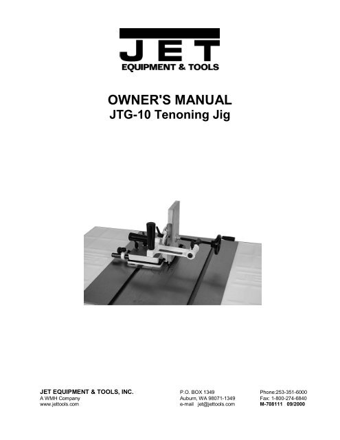
<strong>OWNER'S</strong> <strong>MANUAL</strong>JTG-10 Tenoning JigJET EQUIPMENT & TOOLS, INC. P.O. BOX 1349 Phone:253-351-6000A WMH Company Auburn, WA 98071-1349 Fax: 1-800-274-6840www.jettools.com e-mail jet@jettools.com M-708111 09/2000
Important Information2-YEARLIMITED WARRANTYJET offers a two-year limitedwarranty on this productREPLACEMENT PARTSReplacement parts for this tool are available directly form JET Equipment & Tools.To place an order, call 1-800-274-6848. Please have the following information ready:1. Visa, MasterCard, or Discover Card number2. Expiration date3. Part number listed within this manual4. Shipping address other than a Post Office box.REPLACEMENT PART WARRANTYJET Equipment & Tools makes every effort to assure that parts meet high quality and durability standardsand warrants to the original retail consumer/purchaser of our parts that each such part(s) to be free fromdefects in materials and workmanship for a period of thirty (30) days from the date of purchase.PROOF OF PURCHASEPlease retain your dated sales receipt as proof of purchase to validate the warranty period.LIMITED TOOL AND EQUIPMENT WARRANTYJET makes every effort to assure that its products meet high quality and durability standards and warrants to theoriginal retail consumer/purchaser of our products that each product be free from defects in materials andworkmanship as follows: 2 YEAR LIMITED WARRANTY ON THIS JET PRODUCT. Warranty does not apply todefects due directly or indirectly to misuse, abuse, negligence or accidents, repairs or alterations outside our facilitiesor to a lack of maintenance. JET LIMITS ALL IMPLIED WARRANTIES TO THE PERIOD SPECIFIED ABOVE FROMTHE DATE THE PRODUCT WAS PURCHASED AT RETAIL. EXCEPT AS STATED HEREIN, ANY IMPLIEDWARRANTIES OR MECHANTABILITY AND FITNESS ARE EXCLUDED. SOME STATES DO NOT ALLOWLIMITATIONS ON HOW LONG THE IMPLIED WARRANTY LASTS, SO THE ABOVE LIMITATION MAY NOTAPPLY TO YOU. JET SHALL IN NO EVENT BE LIABLE FOR DEATH, INJURIES TO PERSONS OR PROPERTYOR FOR INCIDENTAL, CONTINGENT, SPECIAL OR CONSEQUENTIAL DAMAGES ARISING FROM THE USE OFOUR PRODUCTS. SOME STATES DO NOT ALLOW THE EXCLUSION OR LIMITATION OF INCIDENTAL ORCONSEQUENTIAL DAMAGES, SO THE ABOVE LIMITATION OR EXCLUSION MAY NOT APPLY TO YOU. Totake advantage of this warranty, the product or part must be returned for examination, postage prepaid, to anauthorized service station designated by our Auburn office. Proof of purchase date and an explanation of thecomplaint must accompany the merchandise. If our inspection discloses a defect, JET will either repair or replace theproduct or refund the purchase price, if we cannot readily and quickly provide a repair or replacement, if you arewilling to accept such refund. JET will return repaired product or replacement at JET’s expense, but if it is determinedthere is no defect, or that the defect resulted from causes not within the scope of JET’s warranty, then the user mustbear the cost of storing and returning the product. This warranty gives you specific legal rights, and you have otherrights, which vary, from state to state.JET Equipment & Tools • P.O. Box 1349, Auburn, WA 98071-1349 • (253) 351-60002
WARNING• Read and understand the entire owner’s manual before attempting assembly or operation.• This tenoning jig is designed and intended for use by properly trained and experiencedpersonnel only. If you are not familiar with the proper and safe operation of a tenoning jig, donot use until proper training and knowledge have been obtained.• Always wear approved (must comply with ANSI Z87.1) safety glasses/face shields while using thismachine.• Make certain workpiece is securely clamped in place and all locking handles are properly tightenedbefore operating.• Before operating the tool, remove tie, rings, watches, other jewelry, and roll up sleeves above theelbows. Remove all loose clothing and confine long hair. Do not wear gloves.• Keep the floor around the machine clean and free of scrap material, oil and grease.• Do not over reach. Maintain a balanced stance at all times.• Make sure machine power is off and blade is stopped before attempting any adjustments to the jig orworkpiece.• Use the right tool. Don't force a tool or attachment to do a job that it was not designed for.• Replace warning labels if they become obscured or removed.• Give your work undivided attention. Looking around, carrying on a conversation, and "horse-play" arecareless acts that can result in serious injury.• Keep visitors a safe distance from the work area.• Never place hands directly in line with the saw blade.• Keep both hands on operating handles provided when processing work material.• Read and understand warnings posted on the machine.• Do not operate the tool while under the influence of drugs, alcohol, or medication.3
Assembly1. Attach the handles (A, Fig. 1) to the clampbracket (B, Fig. 1).2. Attach the clamp bracket to the back of thefence (C, Fig. 1) using two M10x25 hexsocket head screws and two lock washers(D, Fig. 1).3. Insert the handwheel assembly (E, Fig. 1)into the clamp bracket and tighten lockinghandle (F, Fig. 1). Attach the handle to thehandwheel.Note: There are two slots on the under side ofthe tenoning jig base. If you have a JTS-10DD,JWTS-10, a JWCS-10, JTAS-10X JTAS-12 youwill place the slide in the slot closest to thefence, as shown in figure 1. If you have a,JTAS-10XL you will use the slot to the left.However, this can vary depending on the sizeand manufacturer of the tablesaw. WARNINGUnplug the saw from the power source!Use caution when your hands are aroundsaw blades – saw teeth are sharp!Failure to comply may cause serious injury!Alignment & Setup of the Tenoning Jig1. To align the tenoning jig, first place thetenoning jig guide into the saw’s left mitergauge slot.2. Using a square (A, Fig. 2) check to see if thefence is 90° to the saw table. To make anadjustment to the fence, loosen the lockhandle (B, Fig. 2) and adjust the fence to the90° position and tighten lock handle.3. When the fence is 90° to the table, tightenset screw (D, Fig. 2) until it bottoms. Setscrew “D” acts as a positive stop and allowsyou to quickly position the fence back to the90° position after it has been tilted.4. Using a square (A, Fig. 3) check to see if theposition of the backstop (B, Fig. 3) is 90° tothe saw table. If not, loosen the lock handle(C, Fig. 3), adjust the backstop to the 90°position, and tighten the lock handle.5. When the backstop is 90° to the table,adjust the set screw (D, Fig. 3) until ittouches the backstop. Tighten the jam nut.Set screw “D” acts as a positive stop andallows you to quickly position the backstopback to the 90° position after it has beentilted.4
6. Loosen locking handle (I, Fig. 4). Loosenthumb screw (F, Fig. 4), and move bracket(E, Fig. 4) to the back edge of the guide rod(B, Fig. 4). The guide bushing should moveout with the bracket. If the guide bushingdoes not move lubricate with a light oil.Tighten locking handle (I, Fig. 4), and thumbscrew (F, Fig. 4).7. To bring the fence into parallel with the sawblade, loosen both locking handles (D & I,Fig. 4). Reposition the jig so that the fencelies flat against the saw blade and tightenboth locking handles.8. The miter bar slots in the base are milled tobe parallel to the fence. If an adjustment isnecessary, loosen the two hex socket headscrews (A, Fig. 5) holding the guide rod tothe base. Place the jig back into the miterslot. Loosen locking handle (D, Fig. 4) andmake the needed adjustment. Tighten thehandle and remove the jig when adjustmentis made, and fully tighten the screws underthe guide rod. Place the jig back on the sawwith the miter bar in the miter slot.9. Loosen both locking handle (D & I, Fig. 4)and back off jig so that the fence (C, Fig. 4)is approximately 1/8” away from the sawblade and tighten both locking handles (D &I, Fig. 4).10. To prevent the fence from being pushed, ormoved, into the blade, loosen the nut (G,Fig. 4), on the set screw (H, Fig. 4) and turnthe set screw clockwise until it bottoms out.Tighten down the nut.11. For a final adjustment, loosen screw (A, Fig.4) holding the pointer and adjust pointer tothe 1/8” position. Tighten screw.5
Operation of the Tenoning Jig WARNINGYou will need to remove the tablesaw’s bladeguard before using the tenoning jig.Reinstall the blade guard immediately aftertenoning jig use is complete.Always unplug the tablesaw before removingor installing the blade guard.Failure to comply may cause serious injury!1. Use the handwheel (B, Fig. 7) to tightenyour workpiece against the fence.2. Use the two large handles (A, Fig. 7) tosecurely move the workpiece through thesaw blade. Never pass the jig back over themoving saw blade. Wait until the power isoff and the blade comes to a complete stop.3. For rapid or large adjustments moving thefence toward or away from the saw blade,loosen both locking handles (C & D, Fig. 7).Move the jig into position and tighten bothlocking handles (C & D, Fig. 7).4. For fine adjustments moving the fencetoward or away from the saw blade, loosenboth locking handles (C & D, Fig. 7). Movethe jig away from the saw blade and tightenlock handle (C, Fig. 7) only. Move the jiginto position with knob (F, Fig. 7) and thentighten locking handle (D, Fig. 7).5. If it is necessary to cut a tenon on the side ofthe workpiece that is against the fence, awood spacer must be secured between theworkpiece and the fence. This will keep thesaw blade from hitting the fence, (figure 8).Note: there are four holes in the fence sothat a wooden block can be mounted to thefence.6
JTG-10 Tenoning Jig Breakdown7
Parts List for the JTG-10 Tenoning JigIndex PartNo. No. Description Size Qty.1..........JTG10-1....................... Locking Lever .................................................... M6x22 ........................22..........TS-0680022 ................. Flat Washer ....................................................... 1/4”.............................33..........JTG10-3....................... Bracket.............................................................. ...................................14..........JTG10-4....................... Pan Head Machine Screw.................................. M5x10 ........................25..........JTG10-5....................... Scale ................................................................. ...................................16..........JTG10-6....................... Locking Lever .................................................... M6x30 ........................17..........TS-1540041 ................. Hex Nut ............................................................. M6..............................28..........JTG10-8....................... Hex Socket Set Screw ....................................... M6x40 ........................19..........JTG10-9....................... Handle............................................................... ...................................210........JTG10-10..................... Lock Bushing..................................................... ...................................111........TS-1550061 ................. Washer.............................................................. M8..............................112........JTG10-12..................... Lead Screw ....................................................... ...................................113........JTG10-13..................... Slide .................................................................. ...................................114........JTG10-14..................... Hex Nut ............................................................. M10 ............................215........JTG10-15..................... Threaded Bushing ............................................. ...................................116........JTG10-16..................... Guide Bushing................................................... ...................................117........JTG10-17..................... Roll Pin.............................................................. M3x20 ........................118........JTG10-18..................... Knob.................................................................. ...................................119........JTG10-19..................... Knob.................................................................. ...................................120........JTG10-20..................... Bushing ............................................................. ...................................121........JTG10-21..................... Bracket.............................................................. ...................................122........JTG10-22..................... Guide Rod ......................................................... ...................................123........JTG10-23..................... Base.................................................................. ...................................124........JTG10-24..................... Pan Head Machine Screw.................................. M6x20 ........................225........JTG10-25..................... Pan Head Machine Screw.................................. M6x12 ........................226........JTG10-26..................... Guide Bar .......................................................... ...................................126-1.....JTG10-26-1.................. Guide Washer.................................................... ...................................126-2.....JTG10-26-2.................. Flat Head Machine Screw.................................. 1/4x3/8 .......................127........JTG10-27..................... Set Screw.......................................................... M8x50 ........................128........TS-0680041 ................. Washer.............................................................. 3/8”.............................229........TS-1540061 ................. Hex Nut ............................................................. M8..............................230........JTG10-30..................... Locking Handle.................................................. M8..............................131........JTG10-31..................... Pan Head Machine Screw.................................. M4x8 ..........................132........JTG10-32..................... Pointer............................................................... ...................................133........JTG10-33..................... Fence ................................................................ ...................................134........JTG10-8....................... Hex Socket Set Screw ....................................... M6x40 ........................135........JTG10-35..................... Stop................................................................... ...................................137........JTG10-37..................... Stud................................................................... ...................................138........TS-1523071 ................. Hex Socket Set Screw ....................................... M6x25 ........................139........JTG10-39..................... Stud................................................................... ...................................240........JTG10-40..................... Clamp Bracket................................................... ...................................142........JTG10-42..................... Support Shaft..................................................... ...................................145........JTG10-45..................... Handle............................................................... ...................................147........JTG10-47..................... Handwheel ........................................................ ...................................148........JTG10-48..................... Hex Socket Set Screw ....................................... M6x8 ..........................149........JTG10-49..................... Clamp................................................................ ...................................150........TS-1551071 ................. Lock Washer...................................................... M10 ............................251........TS-1505031 ................. Socket Head Cap Screw.................................... M10x25 ......................252........JTG10-52..................... Locking Handle.................................................. ...................................1............JTG10-54..................... Hex Wrench (not shown).................................... M3..............................1............JTG10-55..................... Hex Wrench (not shown).................................... M4..............................1............JTG10-57..................... Hex Wrench (not shown).................................... M8..............................18