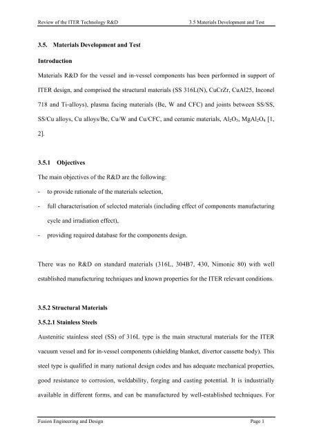
3.5. Materials Development and Test Introduction Materials R&D for ...
3.5. Materials Development and Test Introduction Materials R&D for ...
3.5. Materials Development and Test Introduction Materials R&D for ...

You also want an ePaper? Increase the reach of your titles
YUMPU automatically turns print PDFs into web optimized ePapers that Google loves.
Review of the ITER Technology R&D<br />
3.5 <strong>Materials</strong> <strong>Development</strong> <strong>and</strong> <strong>Test</strong><br />
<strong>3.5.</strong> <strong>Materials</strong> <strong>Development</strong> <strong>and</strong> <strong>Test</strong><br />
<strong>Introduction</strong><br />
<strong>Materials</strong> R&D <strong>for</strong> the vessel <strong>and</strong> in-vessel components has been per<strong>for</strong>med in support of<br />
ITER design, <strong>and</strong> comprised the structural materials (SS 316L(N), CuCrZr, CuAl25, Inconel<br />
718 <strong>and</strong> Ti-alloys), plasma facing materials (Be, W <strong>and</strong> CFC) <strong>and</strong> joints between SS/SS,<br />
SS/Cu alloys, Cu alloys/Be, Cu/W <strong>and</strong> Cu/CFC, <strong>and</strong> ceramic materials, Al 2 O 3 , MgAl 2 O 4 [1,<br />
2].<br />
<strong>3.5.</strong>1 Objectives<br />
The main objectives of the R&D are the following:<br />
- to provide rationale of the materials selection,<br />
- full characterisation of selected materials (including effect of components manufacturing<br />
cycle <strong>and</strong> irradiation effect),<br />
- providing required database <strong>for</strong> the components design.<br />
There was no R&D on st<strong>and</strong>ard materials (316L, 304B7, 430, Nimonic 80) with well<br />
established manufacturing techniques <strong>and</strong> known properties <strong>for</strong> the ITER relevant conditions.<br />
<strong>3.5.</strong>2 Structural <strong>Materials</strong><br />
<strong>3.5.</strong>2.1 Stainless Steels<br />
Austenitic stainless steel (SS) of 316L type is the main structural materials <strong>for</strong> the ITER<br />
vacuum vessel <strong>and</strong> <strong>for</strong> in-vessel components (shielding blanket, divertor cassette body). This<br />
steel type is qualified in many national design codes <strong>and</strong> has adequate mechanical properties,<br />
good resistance to corrosion, weldability, <strong>for</strong>ging <strong>and</strong> casting potential. It is industrially<br />
available in different <strong>for</strong>ms, <strong>and</strong> can be manufactured by well-established techniques. For<br />
Fusion Engineering <strong>and</strong> Design Page 1
Review of the ITER Technology R&D<br />
3.5 <strong>Materials</strong> <strong>Development</strong> <strong>and</strong> <strong>Test</strong><br />
ITER, only minor modifications in chemical composition are required, in order to cope with<br />
the radiological safety limits <strong>and</strong> with the re-welding requirement.<br />
The safety implications of the cobalt (Co) <strong>and</strong> niobium (Nb) content show the following:<br />
- activated cobalt plays an important role in determining occupational dose level during<br />
maintenance <strong>and</strong> in the case of accidents,<br />
- reducing the Co content from 0.25% to 0.05% decreases the total decay heat in the<br />
vacuum vessel by ~20% <strong>and</strong> helps to reduce the activation of components;<br />
- further decrease of Co to 0.01% does not further reduce the decay heat because the<br />
Ni 60 (n,p) Co 60 reaction becomes dominant;<br />
- cobalt is one of the main components of activated corrosion products in the water<br />
cooling system;<br />
- niobium produces long-lived radioisotopes that could become important <strong>for</strong> the<br />
decommissioning <strong>and</strong> waste disposal of in-vessel components.<br />
In 316 type SS, niobium is present as a trace element picked up during the melting<br />
process from the ferroalloy addition: existing data indicate that it is possible to reduce<br />
Nb to ≤0.01%.<br />
Vacuum vessel, manifold <strong>and</strong> branch pipe connections must remain weldable throughout the<br />
machine lifetime in spite of the He generated by neutron irradiation. The helium content<br />
generated by gaseous transmutation should be kept as low as possible, preferably below 1<br />
appm. Boron gives the most significant helium generation during irradiation. There<strong>for</strong>e, the<br />
boron concentration in the steel used <strong>for</strong> the vacuum vessel, manifold <strong>and</strong> water cooling<br />
branch pipes should be as low as feasible industrially. The reduction of boron from 20 wppm<br />
(typical content) to industry feasible level of about 10 wppm lowers the helium generation by<br />
~44%.<br />
Fusion Engineering <strong>and</strong> Design Page 2
Review of the ITER Technology R&D<br />
3.5 <strong>Materials</strong> <strong>Development</strong> <strong>and</strong> <strong>Test</strong><br />
For application in ITER, st<strong>and</strong>ard chemical composition of 316L type steel has been<br />
modified, in order to cope with radiological safety limits <strong>and</strong> with the re-weldability<br />
requirement. The modified stainless steel 316L(N)-IG has the suffix IG (ITER Grade) to<br />
indicate modification, <strong>and</strong> (N) gives an indication of controlled nitrogen content. The<br />
chemical composition of 316L(N)-IG steel is given in Table 1.<br />
The key R&D directions <strong>for</strong> the stainless steel are the following:<br />
- effect of components manufacturing cycle on the material properties,<br />
- effect of neutron irradiation,<br />
- re-weldability tests after irradiation,<br />
- corrosion behaviour of SS.<br />
(1) Effect of manufacturing cycle<br />
Hot isostatic pressing (HIP) process is one of the options <strong>for</strong> the shield blanket modules <strong>and</strong><br />
<strong>for</strong> divertor cassett body manufacturing (see 3.3 <strong>and</strong> 3.4). A study of the effects of HIP cycles<br />
on the mechanical properties of solid <strong>and</strong> power HIPed steels has been per<strong>for</strong>med in the<br />
frame of ITER R&D. It was shown that the tensile properties of HIPed steel are within the<br />
design allowables. In some cases the yield strength of solid-HIPed base metal is close to the<br />
minimum specified values [3]. Powder-HIP gives tensile properties slightly above the<br />
average of the wrought material [4, 5]. Summary of tensile strength tests of 316L(N) type<br />
steel after different manufacturing cycle is presented in Figure 1. In brackets are given<br />
reference to laboratory <strong>and</strong> HT where tests have been per<strong>for</strong>med.<br />
Casting of SS was proposed as a manufacturing options <strong>for</strong> the divertor cassette body, <strong>and</strong><br />
the shielding part of the first wall modules, because it is cheaper than conventional welding<br />
Fusion Engineering <strong>and</strong> Design Page 3
Review of the ITER Technology R&D<br />
3.5 <strong>Materials</strong> <strong>Development</strong> <strong>and</strong> <strong>Test</strong><br />
or HIPing (see §3.3 <strong>and</strong> §3.4). The precision casting technique <strong>for</strong> the divertor cassette has<br />
been developed by the US Home Team [6], <strong>and</strong> the material characterization has been<br />
per<strong>for</strong>med by the US <strong>and</strong> RF Home Teams [6, 7]. The results of investigation show that nonmetallic<br />
inclusions from mould products have not been observed in the castings <strong>for</strong> the<br />
prototype of the divertor cassette body <strong>and</strong> are not present when employing good foundry<br />
practice. The strength of cast <strong>and</strong> HIPed steel is slightly lower than reference data <strong>for</strong> the<br />
wrought steel (see Figure 1). Cast SS exhibits relatively good fracture toughness, <strong>and</strong> very<br />
low crack growth rate indicative of high resistance to cracking. The Straus method, the<br />
Electrochemical Reactivation (EPR) method <strong>and</strong> crack growth rate measurements did not<br />
indicate any susceptibility of cast SS 316L(N)-IG to stress corrosion cracking [7, 8].<br />
(2) Irradiation effect on SS.<br />
Neutron irradiation is another factor which affects the properties of stainless steel. Extensive<br />
irradiation tests have been provided within the ITER task activity. The overview of the results<br />
of irradiation R&D has been presented in several publications [2, 4, 9, 10]. The last results of<br />
irradiation tests of stainless steel with different manufacturing cycle are presented in Table 2.<br />
At the expected neutron fluence ~ 0.3 MWa/m 2 , the peak damage in the steel <strong>for</strong> the in-vessel<br />
components will be ~ 2 dpa with a peak He generation of about 55 appm. The irradiation<br />
temperature <strong>for</strong> these components is in the range 100-300°C. The result of investigation<br />
shows that hardening of the steel will occur, but predicted uni<strong>for</strong>m <strong>and</strong> total elongation of the<br />
wrought <strong>and</strong> powder HIPed steel will remain higher than 10% <strong>and</strong> 20%, respectively, at the<br />
end of the components operation phase [10, 11]. For the solid-HIP steel, the estimated<br />
uni<strong>for</strong>m <strong>and</strong> total elongation will be above 18% <strong>and</strong> 31%, respectively. There<strong>for</strong>e, materials<br />
will be relatively ductile <strong>and</strong> retain work hardening capability during ITER life-time [1, 10].<br />
Results of post irradiation tensile tests shows that even <strong>for</strong> displacement doses up to 4-5 dpa<br />
Fusion Engineering <strong>and</strong> Design Page 4
Review of the ITER Technology R&D<br />
3.5 <strong>Materials</strong> <strong>Development</strong> <strong>and</strong> <strong>Test</strong><br />
the material after all types of manufacturing cycle exhibits a relatively high ductility (see<br />
Table 2), <strong>and</strong> fracture of components due to flow localisation in irradiated steel can be<br />
avoided during the design. Irradiation has been per<strong>for</strong>med at 175±15°C <strong>and</strong> 265±15°C [11].<br />
Data given in Table 2 refer to irradiation temperature 265°C where irradiation effect was<br />
more significant.<br />
The fracture toughness of SS decreases up to 5-6 times after ~ 4 dpa irradiation <strong>and</strong> then<br />
slowly decreases with higher doses of irradiation [4]. For the powder HIPed steel showing<br />
most significant irradiation effect compared with other materials, the fracture toughness<br />
decreases with increasing dose from ~1000 kJ/m 2 in the unirradiated steel to ~ 250-255 kJ/m 2<br />
after 2-2.5 dpa at 77-290°C [4, 5].<br />
(3) Re-welding of irradiated material<br />
The quality of re-welded steel depends on the welding procedure <strong>and</strong> on the He content in<br />
SS. The current assumption, based on existing data, is that re-welding of 316L(N)-IG can be<br />
successfully carried out when the He contents is less than 1 appm. Nevertheless, the reweldability<br />
study per<strong>for</strong>med by the JA HT shows that there is a potential of sound re-welding<br />
of irradiated material with higher helium concentration (up to 3-10 appm) if precision<br />
tungsten inert gas arc (TIG) or yttrium-aluminium-garnet (YAG) laser welding technique<br />
with low energy is applied [12, 13].<br />
To minimise the probability of crack <strong>for</strong>mation during re-welding, it is recommended:<br />
- to minimise He content <strong>and</strong> radiation dose <strong>for</strong> the irradiated areas (as low as<br />
possible),<br />
- to minimise the heat input during welding,<br />
- to minimise (or avoid) tensile stresses <strong>and</strong>/or to provide compressive stresses during<br />
welding.<br />
Fusion Engineering <strong>and</strong> Design Page 5
Review of the ITER Technology R&D<br />
3.5 <strong>Materials</strong> <strong>Development</strong> <strong>and</strong> <strong>Test</strong><br />
(4) Corrosion behaviour<br />
The water chemistry is the key requirement to avoid or minimise corrosion damage of<br />
materials. Result of analysis lead to decision that neutral pH, hydrogen water chemistry<br />
(HWC) shall be used <strong>for</strong> the ITER cooling system. The main results of corrosion effect study<br />
at the ITER working conditions are given in refs. [14, 15].<br />
The estimation of corrosion rate of steel in the ITER working conditions (neutral water<br />
chemistry <strong>and</strong> temperature ~ 100-200°C) shows that corrosion rate decreases with time, <strong>and</strong><br />
varies from ~0.5 to ~1 µm/y [15].<br />
Three methods have been used <strong>for</strong> the revealing steel to SCC: Straus method, electrochemical<br />
reactivation (EPR) <strong>and</strong> slow strain rate tests (SSRT). Results of R&D show the following:<br />
- Wrought 316L(N)-IG steel, base metal after one HIP cycle, powder HIPed, cast material,<br />
solid HIPed joints SS/SS, TIG welded joints are not susceptible to SCC.<br />
- The steel anneal at 550°C during 15h does not result in sensitisation of steel products.<br />
- Anneal at 675°C during 15h gives severe SCC sensitisation of cast SS (EPR parameter<br />
increases up to 1.12%). Wrought SS shows approximately twice better resistance to SCC<br />
than cast SS. Sensitisation behaviour of heat-affected zone of welded joints is similar to<br />
base metal.<br />
- Heat treatment at 675°C <strong>for</strong> 50 h results in sensitisation to SCC of the cast SS. This<br />
sensitisation was revealed by Strauss method, oxalic acid etching <strong>and</strong> by EPR tests (EPR<br />
parameter was about 10%).<br />
Fusion Engineering <strong>and</strong> Design Page 6
Review of the ITER Technology R&D<br />
3.5 <strong>Materials</strong> <strong>Development</strong> <strong>and</strong> <strong>Test</strong><br />
- No SCC of unirradiated 316L(N)-IG observed with SSRT <strong>and</strong> constant de<strong>for</strong>mation<br />
testing (CDT) in pure water, water plus hydrogen, <strong>and</strong> water plus oxygen <strong>and</strong>/or<br />
hydrogen peroxide in the temperature range 90°C-320°C.<br />
- No SCC of 316L(N)-IG SS observed with in-pile testing consisting CDT specimens<br />
irradiated at 200°C in water plus oxygen (> 10 wppm) <strong>and</strong> hydrogen peroxide (>3 wppm)<br />
up to about 3 dpa.<br />
- No SCC of unirradiated 316L(N)-IG SS observed at 320°C with SSRT <strong>and</strong> CDT in<br />
neutral solution of chloride, sulphate <strong>and</strong> copper ions, containing about 2 wppm of<br />
hydrogen. However, with addition of 1-30 wppm of hydrogen peroxide to simulate<br />
possible water radiolysis, SCC occurred on sensitised specimens after 1500 hours of<br />
exposure. In simulated acidic hide-out environment containing chloride <strong>and</strong> sulphate as<br />
observed in BWRs, 316L(N)-IG SS is sensitive to SCC at 340°C.<br />
- No corrosion effect was observed on fatigue behaviour of 316L(N)-IG SS at 320°C after<br />
10 5 cycles at 0.5% strain amplitude.<br />
The estimation (by RF HT) of time to crack appearance during drying was based on the<br />
following relatively conservative assumption:<br />
- tension stress are close to yield stress,<br />
- presence of chloride or fluoride ions in the water (assisted corrosion cracking) <strong>and</strong><br />
- presence of oxidizer (oxygen, hydrogen peroxide) in the water.<br />
The chloride concentration was assumed <strong>for</strong> the analysis at the saturation level, ~240g/kg.<br />
Time to appearance of crack during drying depends on impurities content in drying gas. For<br />
high purity gases (nitrogen <strong>and</strong> helium) time to cracking will be <strong>for</strong> about few thous<strong>and</strong><br />
hours. For the gases with impurities (in particular oxygen) the time to cracking could be<br />
Fusion Engineering <strong>and</strong> Design Page 7
Review of the ITER Technology R&D<br />
3.5 <strong>Materials</strong> <strong>Development</strong> <strong>and</strong> <strong>Test</strong><br />
about a few hours. It was recommended to use <strong>for</strong> the drying only high purity gases <strong>and</strong> to<br />
per<strong>for</strong>m drying at low temperature.<br />
<strong>3.5.</strong>2.2 Copper Alloys<br />
High thermal conductivity, high strength, satisfactory thermal <strong>and</strong> radiation resistance are<br />
required <strong>for</strong> the heat sink materials of the ITER first wall, divertor <strong>and</strong> limiter. Two Cubased<br />
alloys have been retained as c<strong>and</strong>idate heat sink materials <strong>for</strong> the high heat flux<br />
components: CuCrZr <strong>and</strong> GlidCop ® Al25. Rationale <strong>for</strong> the selection of copper alloys is given<br />
in refs. [2, 16, 17, 18].<br />
Starting from the original specification, a tighter limitation <strong>for</strong> composition <strong>and</strong> a specific<br />
heat treatment were proposed <strong>for</strong> the CuCrZr alloy, with the definition of an ITER grade (IG)<br />
specification, CuCrZr-IG. The proposed composition of CuCrZr alloy differs from the<br />
st<strong>and</strong>ard one, mainly by its narrower range of the Cr (0.6-0.9%), Zr (0.07-0.15%) content,<br />
limitation of oxygen (
Review of the ITER Technology R&D<br />
3.5 <strong>Materials</strong> <strong>Development</strong> <strong>and</strong> <strong>Test</strong><br />
creep-fatigue <strong>for</strong> both CuCrZr-IG <strong>and</strong> CuAl25-IG alloys, effect of manufacturing heat<br />
treatment on the properties degradation of CuCrZr-IG alloy <strong>and</strong> corrosion behaviour of<br />
copper alloys in the ITER working conditions.<br />
(1) Fracture toughness <strong>and</strong> creep/fatigue properties<br />
Low fracture toughness of CuAl25-IG is confirmed by various types of experiments, but the<br />
crack growth is stable <strong>and</strong> fracture is ductile [20, 21, 22, 23]. However, the initiation of crack<br />
nucleation does not appear to be instantaneous. Summarised data of fracture toughness tests<br />
are presented in Figure 2. Anisotropy of fracture toughness are observed <strong>for</strong> CuAl25-IG (see<br />
data in Figure 2 <strong>for</strong> T-L <strong>and</strong> L-T directions). Fracture toughness of CuCrZr-IG decreases with<br />
temperature, but remains considerably higher than in the case of CuAl25-IG. There is a big<br />
difference (approximately in two times) in fracture toughness of CuCuZr-IG measured by US<br />
<strong>and</strong> EU HTs (ORNL <strong>and</strong> VTT data). Further study is needed to determine the reason this<br />
difference in fracture toughness measurement.<br />
Fatigue behaviour of Cu alloy has been studied over the range 10 3 -2x10 5 cycles [24]. Results<br />
of creep-fatigue interactions <strong>and</strong> creep crack growth experiments suggest that the time<br />
dependent cyclic phenomenon may play an important role <strong>for</strong> the CuAl25 in determining the<br />
component’s lifetime. The number of cycles to failure decreases by about 25 times, if during<br />
pulse the hold time varies from 10 to 1000 second [25].<br />
(2) Effects of heat treatment history<br />
Mechanical properties <strong>and</strong> thermal conductivity of CuCrZr alloy are sensitive to heat<br />
treatments (hence to joining technology). During component manufacturing, the base<br />
material is generally subjected to additional thermal cycles e.g. welding, brazing, HIPing, etc.<br />
Brazing, even at relatively low temperatures, results in a significant decrease of strength in<br />
Fusion Engineering <strong>and</strong> Design Page 9
Review of the ITER Technology R&D<br />
3.5 <strong>Materials</strong> <strong>Development</strong> <strong>and</strong> <strong>Test</strong><br />
the case of long-term exposure <strong>and</strong>/or slow cooling rates [26, 27]. Brazing or HIPing at high<br />
temperature can be combined with solution annealing. In this case the brazing/HIPing<br />
temperature should be about 950-980°C, followed by fast cooling <strong>and</strong> ageing at 475-480°C.<br />
The most critical step is the cooling rate from the brazing/HIPing temperature. If a fast<br />
cooling rate can be realised after high temperature brazing/HIPing, the loss of strength is<br />
minimised. About 80 to 90% of the strength of the "ideally" heat treated CuCrZr-IG can be<br />
achieved without deleterious effect of ductility, if the cooling rate (after the thermal exposure<br />
during HIP) is at least 70-180°C/min.<br />
CuAl25-IG shows much less sensitivity to heat treatment than CuCrZr-IG [28, 29]. Thermal<br />
stability is one of the main advantages of CuAl25-IG. This allows a wider flexibility in the<br />
use of different joining technologies <strong>for</strong> high heat flux components.<br />
(3) Irradiation effects on copper alloys<br />
Even low irradiation doses (~ 0.1-0.3 dpa) result in significant change of mechanical<br />
properties of Cu alloys. The irradiation results in increase of strength of Cu alloys at low<br />
temperatures, approximately below 300°C. Strength properties of unirradiated materials<br />
should be used <strong>for</strong> the design analysis as more conservative. At higher temperatures,<br />
approximately above 300°C, the strength of irradiated materials is lower, <strong>and</strong> those values<br />
(strength of irradiated materials) should be used [16, 30].<br />
Ductility of CuCrZr-IG alloy increases with increase of irradiation temperature [16, 18]. At<br />
the irradiation temperatures < 230°C uni<strong>for</strong>m elongation is below 2%, there<strong>for</strong>e criteria <strong>for</strong><br />
immediate plastic strain localisation <strong>and</strong> fracture due to exhausting of ductility should be<br />
Fusion Engineering <strong>and</strong> Design Page 10
Review of the ITER Technology R&D<br />
3.5 <strong>Materials</strong> <strong>Development</strong> <strong>and</strong> <strong>Test</strong><br />
used <strong>for</strong> the design analysis [30]. At the temperatures exceeding 230°C material will be<br />
ductile (uni<strong>for</strong>m elongation is above 2 %), <strong>and</strong> high temperature criteria should be used.<br />
The minimum value of uni<strong>for</strong>m elongation of irradiated CuAl25-IG in the temperature range<br />
100-300°C is below 2% [30]. There<strong>for</strong>e, in all temperature ranges, plastic strain localisation<br />
<strong>and</strong> local fracture criteria should be used <strong>for</strong> structural analysis. Combination of low ductility<br />
<strong>and</strong> decreasing of strength of material results in relatively low stress allowables that might be<br />
critical <strong>for</strong> the ITER components design.<br />
To take into account the embrittlement effect due to irradiation, two additional stress limit<br />
parameters, S e <strong>and</strong> S d , have been included in the ITER structural design criteria [30, 31].<br />
These stress intensities can be used <strong>for</strong> the structural analysis of material to prevent fracture<br />
due to flow localization in materials with low work hardening capability (due to irradiation<br />
effect).<br />
(4) Corrosion behaviour<br />
Corrosion behaviour of copper alloys in the ITER working condition is one of critical issue<br />
<strong>for</strong> life-time <strong>and</strong> reliability of high heat flux components cooled by the water (divertor <strong>and</strong><br />
baffle). Corrosion tests in static water (in autoclave with deaerated <strong>and</strong> demineralised water)<br />
have been per<strong>for</strong>med by RF HT [15]. Corrosion rate varies from 0.3 up to 5 µm/y depending<br />
on exposure time <strong>and</strong> material. <strong>Test</strong> temperature was ~100°C.<br />
In the flowing water (up to 10 m/s) the corrosion rate increases. The measurements<br />
per<strong>for</strong>med by the EU HT [14, 15] show the following:<br />
- Corrosion rate was observed ~ 17 µm/y <strong>for</strong> pure Cu <strong>and</strong> ~ 31 µm/y <strong>for</strong> CuAl25-IG at<br />
about 100 °C <strong>and</strong> under isothermal test conditions.<br />
Fusion Engineering <strong>and</strong> Design Page 11
Review of the ITER Technology R&D<br />
3.5 <strong>Materials</strong> <strong>Development</strong> <strong>and</strong> <strong>Test</strong><br />
- The corroded oxide layer was black, <strong>and</strong> there was no essential differences in the<br />
morphology <strong>and</strong> composition of oxide layer both <strong>for</strong> pure copper <strong>and</strong> CuAl25-IG alloy.<br />
- The erosion-corrosion was not clearly revealed during high flow water tests.<br />
- Hydrogen addition results in lower corrosion rate (<strong>and</strong> thin surface oxide layer).<br />
There was no evidence of galvanic corrosion effect in contact with stainless steel due to the<br />
very low electrical conductivity of the water.<br />
<strong>3.5.</strong>2.3 Ti Alloys Irradiation Effects<br />
For the blanket flexible supports, a flexible cartridge in the <strong>for</strong>m of a "squirrel's wheel" is<br />
screwed into the vessel from one side <strong>and</strong> bolted through access holes in the blanket. The<br />
material should have a high strength, because of high axial loading <strong>for</strong>ce, <strong>and</strong> at the same<br />
time allow <strong>for</strong> a wide range of elastic de<strong>for</strong>mation during bending. The estimated temperature<br />
range of the flexible cartridge is between 100 <strong>and</strong> 260˚C, <strong>and</strong> damage dose is ~ 0.1 dpa.<br />
Among the commercial Ti alloys, Ti-6Al-4V (α+β alloy) was proposed as reference grade.<br />
Since it is widely used, there is an industrial experience in many fields <strong>and</strong> the data base of<br />
unirradiated material is relatively complete. The R&D on Ti alloys included study of<br />
irradiation effect on the mechanical properties (tensile, fatigues, fracture toughness) <strong>and</strong><br />
structural stability of alloys under irradiation [32, 33].<br />
Ti alloy property change due to irradiation were studied <strong>for</strong> doses in the range 0.01-0.4 dpa<br />
<strong>and</strong> temperatures 40-350°C. The following general conclusion can be made from the results<br />
of R&D:<br />
- Strength of all materials is increased due to irradiation.<br />
Fusion Engineering <strong>and</strong> Design Page 12
Review of the ITER Technology R&D<br />
3.5 <strong>Materials</strong> <strong>Development</strong> <strong>and</strong> <strong>Test</strong><br />
- Ductility is decreased. However, in all experiments (even at dose ~0.4 dpa) the<br />
uni<strong>for</strong>m elongation was above 2%. There<strong>for</strong>e, structural criteria of ductile<br />
materials can be used <strong>for</strong> the design analysis.<br />
- There was no significant alteration of fatigue lifetime due to irradiation.<br />
- Fracture toughness decreases (2-5 times) due to irradiation. Nevertheless, fracture<br />
toughness remains at a relatively high level (~20-60 kJ/m 2 at 20°C).<br />
Alpha-based Ti alloy (Ti-5Al-2.4Sn) exhibited less embrittlement due to irradiation [32].<br />
However, the strength of alpha-based alloy is lower than that of the alpha-beta alloy. Ti-5Al-<br />
2.4Sn alloy is there<strong>for</strong>e considered as a back-up option.<br />
It is known that Ti alloys might be susceptible to hydrogen embrittlement in certain<br />
conditions. The cartridge operates in the environment of the vacuum chamber, but it is<br />
shielded from the direct bombardment of energetic particles by the module itself. The<br />
possibility of hydrogen or helium implantation by energetic particles is, there<strong>for</strong>e, eliminated.<br />
Available data indicate that a relatively high hydrogen content of 3-5 wt. % is necessary to<br />
produce significant embrittlement, in terms of impact fracture energy, in Ti alloys. ITER<br />
R&D shows that hydrogen saturation of Ti-6Al-4V alloy up to 200 wppm of hydrogen did<br />
not result in changes of tensile properties both <strong>for</strong> unirradiated <strong>and</strong> irradiated material [33].<br />
<strong>3.5.</strong>2.4 Ni-based Alloys Irradiation Effects<br />
High strength, fatigue <strong>and</strong> fracture toughness are required <strong>for</strong> the bolt attaching the shielding<br />
blanket modules through the flexible support to minimise the size of attached units <strong>and</strong> to<br />
provide reliability of the attachment. Inconel 718 is selected as the reference material due to<br />
its high strength <strong>and</strong> good ductility. Inconel 718 has satisfactory fracture toughness <strong>and</strong><br />
Fusion Engineering <strong>and</strong> Design Page 13
Review of the ITER Technology R&D<br />
3.5 <strong>Materials</strong> <strong>Development</strong> <strong>and</strong> <strong>Test</strong><br />
fatigue lifetime. Data on the radiation behaviour of Inconel 718 is sparse. Results of<br />
irradiation tests show that irradiation up to 0.5 dpa will result in an increase of strength <strong>and</strong> in<br />
a slight decrease of ductility that will not affect the component structural integrity <strong>and</strong><br />
lifetime [34].<br />
Radiation induced stress relaxation is one of the critical issue <strong>for</strong> the bolts feasibility. Results<br />
of stress relaxation investigations per<strong>for</strong>med by the EU HT [34, 35, 36] show that <strong>for</strong> the<br />
bolts of flexible cartridge fastenings where the irradiation dose is ~ 0.02-0.1 dpa, the stress<br />
relaxation will be ~ 80-90% from initial pre-load to the end of life, so, the required pre-stress<br />
should be ~ 800 MPa.<br />
<strong>3.5.</strong>3 Plasma Facing <strong>Materials</strong><br />
The choice of plasma facing materials <strong>for</strong> different components is determined mainly by<br />
plasma compatibility <strong>and</strong> erosion lifetime (ion erosion, thermal erosion during disruption <strong>and</strong><br />
transient events) [37].<br />
- Beryllium has been chosen as the armour material <strong>for</strong> the first wall <strong>and</strong> port limiter,<br />
- Tungsten has been selected as the material <strong>for</strong> the divertor baffle area with high<br />
concentration of neutral particles due to lowest erosion rate,<br />
- Carbon fibre composites (CFC) have been proposed <strong>for</strong> the lower part of the divertor<br />
vertical target due to absence of melting during plasma disruptions.<br />
The key issues related to the plasma-wall interaction phenomena have been discussed<br />
elsewhere [37]. In this section the following R&D results will be highlighted:<br />
- evaluation of the different armour material grades <strong>and</strong> the selection of the reference<br />
grade <strong>for</strong> the ITER application,<br />
Fusion Engineering <strong>and</strong> Design Page 14
Review of the ITER Technology R&D<br />
3.5 <strong>Materials</strong> <strong>Development</strong> <strong>and</strong> <strong>Test</strong><br />
- justification of the material per<strong>for</strong>mance at ITER specific conditions (neutron<br />
irradiation effect, thermal fatigue/thermal shock resistance, etc.).<br />
<strong>3.5.</strong>3.1 Beryllium<br />
Based on the R&D results, S-65C VHP (vacuum hot pressed) grade (manufacturer Brush<br />
Wellman Inc., USA) has been selected as a reference grade. DShG-200, the RF Home Team<br />
<strong>and</strong> plasma sprayed (PS) Be are considered as a back-up option.<br />
The R&D activity has been focused on:<br />
- study of the thermal fatigue <strong>and</strong> thermal shock resistance of the different Be grades,<br />
- study of the neutron irradiation effect on the properties <strong>and</strong> thermal per<strong>for</strong>mance of<br />
Be,<br />
- development of the Be plasma spray technology <strong>and</strong> optimisation of the properties of<br />
PS Be.<br />
(1) Thermal per<strong>for</strong>mance<br />
The comparative studies of the thermal fatigue <strong>and</strong> thermal shock resistance have been<br />
per<strong>for</strong>med by the US, EU <strong>and</strong> RF Home Teams [38, 39]. More than 15 different industrial Be<br />
grades were tested. The results are briefly summarised as follows:<br />
- S-65C VHP (vacuum hot pressed) <strong>and</strong> DShG-200 Be grades have been determined as<br />
materials with the best thermal fatigue resistance,<br />
- thermal shock tests (0.2-3 GW/m 2 , 5 ms) of the different grades show that S-65C<br />
VHP has generally better per<strong>for</strong>mance (lower thermal erosion <strong>and</strong> crack <strong>for</strong>mation),<br />
- simulation tests of VDE demonstrated the structural integrity (absence of the<br />
macroscopic destruction) of the Be S-65C,<br />
Fusion Engineering <strong>and</strong> Design Page 15
Review of the ITER Technology R&D<br />
3.5 <strong>Materials</strong> <strong>Development</strong> <strong>and</strong> <strong>Test</strong><br />
- thermal shock tests of the neutron irradiated Be revealed the slight increase of the<br />
thermal erosion, He bubble <strong>for</strong>mation has been observed in the re-solidified layers.<br />
(2) Irradiation effects on Be<br />
The comprehensive studies of the neutron irradiation effect on the beryllium properties have<br />
been carried out in all Home Teams, [40, 41, 42, 43] <strong>and</strong> these results were summarised in<br />
[44]. For ITER operational conditions there is no significant influence on the physical<br />
properties (including swelling). Generally, neutron irradiation causes an increase of tensile<br />
strength <strong>and</strong> a decrease of ductility <strong>and</strong> fracture toughness due to combined effects of neutron<br />
damage <strong>and</strong> helium generation. These are typical <strong>for</strong> all beryllium grades. The quantitative<br />
data <strong>for</strong> the recent grades have been generated. It was shown that <strong>for</strong> expected ITER<br />
conditions (damage ~ 1-1.4 dpa, irradiation temperature ~ 200-400°C) the behaviour of the<br />
recent Be grades (S-65C VHP <strong>and</strong> S-200F) is very similar <strong>and</strong> the ductility will remain in the<br />
level of ~ 1%. Experimental results of ductility change due to irradiation are presented in<br />
Figure 3.<br />
The thermal per<strong>for</strong>mance of the brittle beryllium (after irradiation) is a key issue. However,<br />
there are some positive experiments showing that high heat flux tests of neutron irradiated<br />
mock-ups did not reveal any damage in Be <strong>and</strong> the high heat flux tests of the cracked<br />
unirradiated Be did not reveal any detrimental behaviour due to cracking.<br />
Still more tests of neutron irradiated Be at relevant conditions (1000 appm He, 1-1.4 dpa) are<br />
needed, especially to simulate the VDE conditions <strong>and</strong> further thermal cycling behaviour.<br />
(3) Be plasma spray technology<br />
Fusion Engineering <strong>and</strong> Design Page 16
Review of the ITER Technology R&D<br />
3.5 <strong>Materials</strong> <strong>Development</strong> <strong>and</strong> <strong>Test</strong><br />
US Home Team has per<strong>for</strong>med R&D on the development of the Be plasma spray technology,<br />
[45]. In the frame of this program, the significant improvements of the Be PS properties has<br />
been achieved, e.g. the thermal conductivity of the PS Be could be in the range 100-160<br />
W/mK at density ~ 92%. However, in comparison with S-65C, plasma-sprayed Be has lower<br />
thermal shock resistance <strong>and</strong> lower mechanical properties.<br />
<strong>3.5.</strong>3.2 Tungsten<br />
The R&D activity has been focused on the selection of the W grades based on the behaviour<br />
during thermal loads, simulating normal heat flux, disruption <strong>and</strong> thermal shocks (including<br />
neutron irradiation). Several W grades from different suppliers (pure sintered W, cast W<br />
alloys, W-1%La 2 O 3 , chemical vapour deposited W, monocrystal W, plasma sprayed W etc.)<br />
have been studied. The summary of the results could be found in [46].<br />
Comparative tests of the low cycle fatigue resistance of the 10 different W grades have been<br />
per<strong>for</strong>med by US HT <strong>and</strong> it was concluded that monocrystal W with proper orientation has<br />
the best resistance to thermal fatigue cracking, the next grade is the pure rolled W.<br />
The results of the thermal shock testing of the different W grades shows that weight loss of<br />
the W-1%La 2 O 3 is significantly higher than <strong>for</strong> pure W (JA HT) [47]. The thermal shock<br />
tests per<strong>for</strong>med in EU HT, FZ Juelich have shown that the crack <strong>for</strong>mation in W significantly<br />
depends on temperature <strong>and</strong> the neutron irradiation leads to increasing of the cracks<br />
<strong>for</strong>mation, however, the thermal erosion was not increased, [48]. Thermal fatigue tests at<br />
15MW/m 2 revealed some surface crack <strong>for</strong>mation in the W -1%La 2 O 3 tiles.<br />
Fusion Engineering <strong>and</strong> Design Page 17
Review of the ITER Technology R&D<br />
3.5 <strong>Materials</strong> <strong>Development</strong> <strong>and</strong> <strong>Test</strong><br />
The study of the different W grades at thermal fatigue <strong>and</strong> disruption simulation has been<br />
per<strong>for</strong>med by the RF HT [49]. All tested tungsten grades show good thermal fatigue<br />
per<strong>for</strong>mance at proper armour design up to heat flux of 15 MW/m 2 . Rolled tungsten with<br />
texture orientation perpendicular to heat flow direction shows tendency of delamination at<br />
heat fluxes higher than about 5 MW/m 2 . Disruption simulation tests show that nearly all<br />
tungsten grades suffer from surface cracking except <strong>for</strong> single crystal tungsten. Thermal<br />
fatigue test at 20 MW/m 2 of mock-up after disruption simulation demonstrated that there is<br />
severe crack <strong>for</strong>mation in almost all materials except <strong>for</strong> W-5Re-0.1ZrC alloy <strong>and</strong> W-0.02 Re<br />
single crystal alloy.<br />
Typically <strong>for</strong> bcc metals, neutron irradiation leads to an increase in the ductile-to-brittle<br />
transition temperature (DBTT) [44]. Based on the available data it could be concluded that all<br />
W grades have the problem of brittleness, at the expected fluence of 0.1-0.5 dpa in the region<br />
near the heat sink, <strong>for</strong> an irradiation temperature less than ~ 500°C.<br />
One of the findings from the R&D results is that the key issue is the proper design of the W<br />
armour (size of tiles <strong>and</strong> grain orientation). The recommended grain orientation is parallel to<br />
the direction of the heat flow, in which case possible delamination is not so critical. Based on<br />
the results of R&D the pure sintered W is recommended as reference material <strong>for</strong> divertor<br />
components.<br />
<strong>3.5.</strong>3.3 Carbon Fibre Composites<br />
The R&D activity has been per<strong>for</strong>med in EU <strong>and</strong> JA HTs <strong>and</strong> has been focused on the<br />
following directions [50]:<br />
- development of the new advanced CFCs (including doped) with improved properties,<br />
- characterisation of these new materials,<br />
Fusion Engineering <strong>and</strong> Design Page 18
Review of the ITER Technology R&D<br />
3.5 <strong>Materials</strong> <strong>Development</strong> <strong>and</strong> <strong>Test</strong><br />
- study of the critical issues as neutron irradiation <strong>and</strong> thermal shock/disruption.<br />
Significant progress has been achieved by the EU HT in the development of the new CFCs.<br />
Several new grades as Dunlop, 3D CFC Sepcarb ® NB31, silicon doped CFC with improved<br />
resistance to chemical erosion Sepcarb-inox NS31 have been developed [51, 52]. The key<br />
property <strong>for</strong> CFCs is thermal conductivity, <strong>for</strong> Sepcarb ® NB31 it is in a range 320 W/mK at<br />
room temperature.<br />
JA HT has developed new advanced 3D CFC NIC-01 with thermal conductivity ~ 540<br />
W/mK at room temperature [53].<br />
These new developed materials have been widely studied in comparison with existing grades<br />
with regards to effect of the neutron irradiation <strong>and</strong> thermal shock effect. For ITER condition<br />
(damage ~ 0.1-0.3 dpa <strong>and</strong> irradiation temperature 150-1200°C) the changes in properties are<br />
not expected to be crucial except <strong>for</strong> the thermal conductivity. CFCs with high initial thermal<br />
conductivity retain high conductivity after irradiation, but at low irradiation temperatures<br />
(less than 300°C) the thermal conductivity could be ~ 3-5 times lower than the unirradiated<br />
CFC [44].<br />
The per<strong>for</strong>mances of mock-ups using the Sepcarb ® NB 31 <strong>and</strong> NIC-01 armour tiles have been<br />
studied including irradiation effects. Generally, the per<strong>for</strong>mance was as expected (higher<br />
temperature due to the loss of thermal conductivity). The decrease in the thermal conductivity<br />
due to neutron irradiation leads to an increase in thermal erosion under disruption conditions<br />
<strong>and</strong> this may have to be taken into account during the erosion lifetime assessment.<br />
Fusion Engineering <strong>and</strong> Design Page 19
Review of the ITER Technology R&D<br />
3.5 <strong>Materials</strong> <strong>Development</strong> <strong>and</strong> <strong>Test</strong><br />
The results of the thermal shock testing of the unirradiated <strong>and</strong> irradiated CFCs have been<br />
reported: it was shown that neutron irradiation leads to increasing the thermal erosion of<br />
~1.5-2 times <strong>for</strong> CFC [54, 55]<br />
For ITER application Sepcarb ® NB 31 <strong>and</strong> NIC-01 have been selected as a references grades.<br />
The back-up option is 2D felt-type CFC CX 2002U <strong>and</strong> Sepcarb-inox NS31.<br />
<strong>3.5.</strong>4 Characteristics of Joints of Different <strong>Materials</strong><br />
The design of the ITER Plasma Facing Components (PFCs) involves various combinations of<br />
joints between armour materials <strong>and</strong> Cu alloy heat sinks <strong>and</strong> between Cu alloys <strong>and</strong> austenitic<br />
steels. The joints must withst<strong>and</strong> the thermal, mechanical <strong>and</strong> neutron loads <strong>and</strong> the cyclic<br />
mode of operation <strong>and</strong> operate under vacuum, while providing an acceptable design lifetime<br />
<strong>and</strong> high reliability. This paragraph summarizes the results of the R&D program on the<br />
development of joining technologies <strong>and</strong> properties of joints.<br />
<strong>3.5.</strong>4.1 Characteristics of Be/Cu Joints<br />
The main problem of bonding Be to Cu alloys is that Be reacts with almost all metals at<br />
moderate <strong>and</strong> high temperatures <strong>and</strong> <strong>for</strong>ms brittle intermetallic phases that are detrimental <strong>for</strong><br />
the joint reliability <strong>and</strong> the fatigue lifetime. To solve this problem <strong>and</strong> to provide good quality<br />
Be/Cu joints, different approaches have been studied by the ITER Home Teams. These<br />
approaches have been summarized in [56] as follows.<br />
- Use of materials as fillers or interlayers between Be <strong>and</strong> Cu alloy which do not <strong>for</strong>m<br />
intermetallic phases with Be (e.g. Al, Ge, Si, AlSi or AlBeMet). The joining<br />
temperature <strong>for</strong> these materials is typically equal to or less than the melting<br />
temperature of these filler materials. The room temperature strength of the joint with<br />
Fusion Engineering <strong>and</strong> Design Page 20
Review of the ITER Technology R&D<br />
3.5 <strong>Materials</strong> <strong>Development</strong> <strong>and</strong> <strong>Test</strong><br />
pure Al interlayer is 120 MPa with ductile fracture inside the Al layer. For the<br />
AlBeMet-150 interlayer, the RT tensile strength increased to 195 MPa <strong>and</strong> 100 MPa<br />
at 300°C.<br />
- Use of diffusion barrier materials with less affinity <strong>for</strong> the <strong>for</strong>mation of beryllide<br />
intermetallics. Different types of these barriers have been studied: Ti, Cr, Ti/Ni, Al/Ni<br />
Ti/Cu, Al/Ti/Cu, <strong>and</strong> Cr/Cu. Typically <strong>for</strong> this type of joints, HIP is used as a joining<br />
procedure with the temperature range 500 – 850°C. The shear strength of Be/Cu joints<br />
with Ti interlayer is ~ 108 MPa at room temperature.<br />
- Brazing with Cu-based brazing alloys. At a brazing temperature more than 650°C<br />
(typical temperature <strong>for</strong> these types of brazing alloys) intermetallic <strong>for</strong>mation occurs,<br />
but using a "fast" brazing technique, this <strong>for</strong>mation could be limited.<br />
- Direct bonding of Be to Cu alloy (with or without a soft intermediate layer of Cu) at<br />
moderate temperatures (~ 500-700°C). Direct Be plasma spray can also be carried out<br />
under this condition.<br />
The results of the high heat flux testing of the small-scale mock-ups are described in §3.3. As<br />
a part of the materials R&D program, several small scale Be/Cu mock-ups [57] have been<br />
irradiated (0.3 dpa, 350°C) <strong>and</strong> tested (up to 7 MW/m 2 ) after irradiation <strong>and</strong> Be/Cu brazed<br />
mock-up has been tested in the in-pile (simultaneous neutron 0.2 dpa <strong>and</strong> heat flux 3 MW/m 2<br />
irradiation) [58]. Based on these preliminary results, the conclusion could be made that<br />
neutron irradiation is not so critical <strong>for</strong> the durability of the Be/Cu joints.<br />
<strong>3.5.</strong>4.2 Characteristics of W/Cu Joints<br />
The main problem in the development of W/Cu joints is the large difference in the coefficient<br />
of thermal expansion (CTE) <strong>and</strong> of elastic modulus. From engineering point of view the<br />
Fusion Engineering <strong>and</strong> Design Page 21
Review of the ITER Technology R&D<br />
3.5 <strong>Materials</strong> <strong>Development</strong> <strong>and</strong> <strong>Test</strong><br />
solution is to use brush-like (rectangular or rod) or lamella type of the W armour design <strong>and</strong><br />
use the soft intermediate layer between W <strong>and</strong> heat sink.<br />
The problem of the joining of W <strong>and</strong> Cu could be solved by different methods (see summary<br />
in [56]. One of the studied techniques is the casting of pure Cu onto W <strong>and</strong> further joining of<br />
the W/Cu to heat sink by different methods. The yield tensile strength of W/cast Cu joint is<br />
typically higher than yield strength of pure Cu <strong>and</strong> equal ~ 100-120 MPa. The brazing<br />
technology with CuMn also gives good results. The use of CuMn base brazing alloy<br />
demonstrated a good tensile strength of joint ~ 200 MPa with failure in Cu alloy near the<br />
brazed joint. Direct diffusion bonding of the W tile in the <strong>for</strong>m of rods seems also promising.<br />
The use of W plasma spray gives good joining with Cu alloy heat sink. The use of chemical<br />
vapour deposition (CVD) of W onto Cu produces also good joints, but has limitations in<br />
thickness. Both these methods have been successfully applied <strong>for</strong> manufacturing of the<br />
components with curved surfaces. However, these technologies could be applied only <strong>for</strong><br />
components with low <strong>and</strong> moderate heat flux.<br />
<strong>3.5.</strong>4.3 Characteristics of CFC/Cu Joints<br />
The problem in the development of CFC/Cu joints is worse than <strong>for</strong> the W/Cu joints due to<br />
the even larger difference in the CTE of the materials [56]. To provide a high quality CFC/Cu<br />
joint the surface of the CFC has to be activated to increase the wetting <strong>and</strong> a compliant layers<br />
between the CFC <strong>and</strong> Cu alloy heat sink is needed to relieve the residual stresses. Several<br />
joining technologies have been developed <strong>and</strong> studied.<br />
- Active metal casting (AMC ® ) technology, which was originally developed by Plansee<br />
AG <strong>for</strong> the Tore Supra limiters. This technology includes the special laser treatment<br />
Fusion Engineering <strong>and</strong> Design Page 22
Review of the ITER Technology R&D<br />
3.5 <strong>Materials</strong> <strong>Development</strong> <strong>and</strong> <strong>Test</strong><br />
of the CFC surface, followed by casting of pure Cu onto CFC, machining <strong>and</strong> final<br />
joining with the Cu alloy heat sink. In the monoblock configuration, CFC tiles with<br />
AMC ® Cu can be joined to Cu alloys by brazing or HIP. For flat tiles, the same joint<br />
could be obtained by e-beam welding. AMC ® technology was applied to different<br />
CFC grades (SEP N11, SEP N31, etc.). It was shown that tensile strength of joints<br />
produced by AMC ® technology is ~ 30 MPa which is less than strength of CFCs,<br />
whereas the shear strength is ~ 40-50 MPa.<br />
- Brazing with silver-free alloys (CuMn, CuSiAlTi) <strong>and</strong> HIP-assisted brazing with<br />
CuMn <strong>and</strong> CuTi alloys. The best high heat flux results have been observed <strong>for</strong> CuMn<br />
brazes<br />
As part of the materials R&D program, several small scale CFC/Cu mock-ups have been<br />
irradiated up to ~ 0.3 dpa at 350°C <strong>and</strong> 700°C. After irradiation this mock-up was tested in<br />
the JUDITH facility <strong>and</strong> survived 1000 cycles at 15MW/m 2 , [57]. Similar experiments with<br />
irradiated CFC-Cu mock-ups (irradiated up to fluence ~0.3-0.5dpa at irradiation temperature<br />
~300-340°C) have been per<strong>for</strong>med at the OHBIS – facility by the JA Home Team [59]. No<br />
degradation of the heat flux per<strong>for</strong>mance (except of the expected change of the thermal<br />
conductivity) has been observed. Based on these preliminary results it could be concluded<br />
that neutron irradiation seems not so critical <strong>for</strong> the CFC/Cu joints.<br />
<strong>3.5.</strong>4.4 Characteristics of SS/Cu Joints<br />
Plasma facing components include the following joints <strong>for</strong> Cu alloys <strong>and</strong> stainless steel: <strong>for</strong><br />
the first wall - copper plates with steel cooling tubes <strong>and</strong> plates; <strong>for</strong> limiter <strong>and</strong> divertor -<br />
copper structures with steel plate <strong>and</strong>/or copper <strong>and</strong> steel tubes.<br />
Generally, good bonding of both CuCrZr <strong>and</strong> CuAl25 alloys to SS was achieved.<br />
Fusion Engineering <strong>and</strong> Design Page 23
Review of the ITER Technology R&D<br />
3.5 <strong>Materials</strong> <strong>Development</strong> <strong>and</strong> <strong>Test</strong><br />
For HIP joining the use of CuAl25-IG alloy is preferable due to its excellent resistance to<br />
high temperature heating. Optimised SS/CuAl25-IG joints have good radiation resistance.<br />
Strength of the HIP bonded joints after 0.4 dpa irradiation dose at 150 <strong>and</strong> 300°C is higher<br />
than or equal to that of the base metal, with the failure location within the Cu part close to the<br />
interface [60].<br />
Properties of CuCrZr/SS joints depend on the properties degradation of Cu alloy due to heat<br />
treatment used <strong>for</strong> joining technology. Providing fast cooling (~ 1-2°C/s) <strong>and</strong> applying<br />
further ageing, the properties of CuCrZr-IG after HIP are acceptable [27, 61]. This method<br />
gives high quality bonding <strong>and</strong> tensile properties of joints close to the strength of Cu alloys.<br />
Other joining methods such as explosion bonding seem promising <strong>and</strong> provides a good<br />
quality of joint, but it is applicable only <strong>for</strong> simple geometric shapes of the components. For<br />
Cu tube to stainless steel tube joining, friction welding, diffusion bonding (<strong>for</strong> DS Cu) <strong>and</strong><br />
TIG welding with Ni interlayer (<strong>for</strong> CuCrZr-IG) can be used. The casting of CuCrZr onto<br />
stainless steel also gives a good quality of joint, that is also resistant to neutron irradiation<br />
[62].<br />
The R&D results obtained <strong>for</strong> the joints lead to the following relationship of fracture<br />
resistance:<br />
- base material > joint sample > irradiated joint sample,<br />
- CuCrZr joints >>CuAl25 joints,<br />
- lower temperature data > same at high temperature.<br />
However, results are geometry dependent, <strong>and</strong> the samples do not generally fail at the<br />
interface.<br />
Fusion Engineering <strong>and</strong> Design Page 24
Review of the ITER Technology R&D<br />
3.5 <strong>Materials</strong> <strong>Development</strong> <strong>and</strong> <strong>Test</strong><br />
Thermal fatigue tests of the first wall mock-ups per<strong>for</strong>med by the EU HT <strong>and</strong> JA HT did not<br />
reveal any failure of SS/Cu joints under the following test conditions: 30,000 cycles at 0.75<br />
MW/m 2 , <strong>and</strong> 1000 cycles at 5 MW/m 2 plus 1500 cycles at 7 MW/m 2 [65, 66].<br />
Last generation of HIPed CuAl25/316L(N) <strong>and</strong> CuCrZr/316L(N) joints demonstrate high<br />
level of strength <strong>and</strong> satisfactory (non-zero) ductility after irradiation to 0.4 dpa at 150°C <strong>and</strong><br />
300°C <strong>and</strong> to 2 dpa at 200°C [64]. The tensile strength of CuAl25/316L(N) <strong>and</strong><br />
CuCrZr/316L(N) joints after irradiation (<strong>and</strong> test) at 200°C is about 350 MPa <strong>and</strong> 260 MPa,<br />
respectively, <strong>and</strong> the total elongation of CuCrZr/316L(N) joint is about 13% [67].<br />
<strong>3.5.</strong>4.5 Characteristics of SS/SS Joints<br />
All austenitic stainless steels are readily weldable with a wide range of well-established<br />
methods, such as narrow gap TIG welding, electron beam welding, laser welding. The<br />
properties of the weld are well defined <strong>and</strong> compatible with the load requirement of these<br />
components. For TIG joints, the unirradiated welded material shows in general a higher yield<br />
stress, lower ultimate tensile strength <strong>and</strong> lower ductility than plate material. The effect of<br />
neutron irradiation on the tensile properties is similar to that <strong>for</strong> plate material, i.e. significant<br />
hardening <strong>and</strong> loss of ductility occurs [3]. It is expected that the worst ductility reduction<br />
occurs in the irradiation temperature range of 275-375°C, well above that appropriate <strong>for</strong><br />
ITER.<br />
The joining of stainless steel to steel by HIP is considered as the main method <strong>for</strong> the<br />
manufacturing of the shield blanket modules. The quality of joint strongly depends on the<br />
quality of the base metal <strong>and</strong> on the surface preparation during the HIPing process. Most of<br />
Fusion Engineering <strong>and</strong> Design Page 25
Review of the ITER Technology R&D<br />
3.5 <strong>Materials</strong> <strong>Development</strong> <strong>and</strong> <strong>Test</strong><br />
the tensile data <strong>for</strong> SS/SS HIP joints in unirradiated state are within the design allowable of<br />
the base metal but close to the lower bound of the specified strength [2, 3].<br />
Neutron irradiation has a slight effect on the mechanical properties of the joints,<br />
demonstrating a similar behaviour as <strong>for</strong> the base metal [3]. The last result of irradiation tests<br />
are presented in Table 2 <strong>and</strong>, in more detail, is given in ref. [11].<br />
HIP bonded SS/SS joints <strong>and</strong> powder–HIPed SS seems more sensitive to irradiation<br />
degradation of the fatigue resistance in comparison with wrought SS [3, 5].<br />
<strong>3.5.</strong>5 Ceramic Insulators<br />
Ceramic insulators are proposed to use <strong>for</strong> the limiter plates insulation <strong>and</strong> to provide<br />
electrical insulation of the first wall modules. The electrical resistivity changes due to<br />
irradiation have been studied within the R&D <strong>for</strong> diagnostic components. The objective of<br />
this investigation was to study the structural integrity of irradiated coatings under impact <strong>and</strong><br />
compression loads <strong>and</strong> ability to maintain the electrical resistance after these loads.<br />
Specimens with ceramic insulator coating have been manufactured <strong>and</strong> tested be<strong>for</strong>e<br />
irradiation. These are Al 2 O 3 <strong>and</strong> MgAl 2 O 4 with different substrates. The breakdown voltage<br />
of coating is above 2500V, electrical resistance ~ 10 10 Ω <strong>and</strong> compression strength >200 MPa<br />
that exceeds ITER requirements. The impact tests per<strong>for</strong>med by the JA HT show that the<br />
coating withst<strong>and</strong>s without visible defects 10000 impact cycles with energy ~7-13 kJ/m 2 (by<br />
dropping steel hammer, [68]). Specimens with ceramic coatings have been irradiated in<br />
JMTR reactor. Neutron fluence was ~3x10 20 n/cm 2 (E>1 MeV), irradiation temperatures were<br />
150°C <strong>and</strong> 250°C. Post irradiation mechanical impact tests with impact energy ~ 7-13 kJ/m 2<br />
did not result in failure of coating up to 30000 impact cycles.<br />
Fusion Engineering <strong>and</strong> Design Page 26
Review of the ITER Technology R&D<br />
3.5 <strong>Materials</strong> <strong>Development</strong> <strong>and</strong> <strong>Test</strong><br />
<strong>3.5.</strong>6 Summary<br />
ITER R&D activity provides basis <strong>for</strong> materials selection <strong>and</strong> justification of materials<br />
behaviour <strong>for</strong> different components. The ef<strong>for</strong>t was focused on the optimisation of materials<br />
to meet ITER requirement, study of materials behaviour under ITER working conditions <strong>and</strong><br />
study the effect of component manufacturing on the properties of materials.<br />
On the basis of analysis of available data <strong>and</strong> results of R&D, materials <strong>for</strong> the ITER<br />
components have been prescribed. These are both st<strong>and</strong>ard <strong>and</strong> industrially available<br />
materials (steels, Ti <strong>and</strong> Ni based alloys, tungsten, beryllium, etc.) <strong>and</strong> materials modified <strong>for</strong><br />
better per<strong>for</strong>mance of the ITER components (316L(N) steel, Cu alloys <strong>and</strong> CFC).<br />
The results of the ITER R&D programme support this selection <strong>and</strong> provide the justification<br />
of the material per<strong>for</strong>mance under operational conditions. The key critical issues <strong>for</strong> each<br />
material have been analysed <strong>and</strong> assessed, <strong>and</strong> the operational windows have been<br />
determined.<br />
Fusion Engineering <strong>and</strong> Design Page 27
Review of the ITER Technology R&D<br />
3.5 <strong>Materials</strong> <strong>Development</strong> <strong>and</strong> <strong>Test</strong><br />
List of Tables<br />
Table 1<br />
Table 2<br />
Chemical composition (wt. %) of 316L(N)-IG stainless steel<br />
Tensile properties of 316L(N)-IG SS changes due to irradiation<br />
List of Figures<br />
Fig. 1<br />
Fig. 2<br />
Summary of tensile tests per<strong>for</strong>med in different laboratories<br />
Fracture toughness of unirradiated Cu alloys. (T <strong>and</strong> L is transverse <strong>and</strong><br />
longitudinal directions, respectively, indicating tension <strong>and</strong> crack propagation<br />
relative to the rolling direction of plate. References in figure: OMG [19], ORNL<br />
[21], VTT [22, 23])<br />
Fig. 3<br />
Change of the total elongation of the Be S-65C VHP after neutron irradiation<br />
Fusion Engineering <strong>and</strong> Design Page 28
Review of the ITER Technology R&D<br />
3.5 <strong>Materials</strong> <strong>Development</strong> <strong>and</strong> <strong>Test</strong><br />
Table 1. Chemical composition (wt. %) of 316L(N)-IG stainless steel<br />
Element Reference grade: 316L(N)-IG<br />
min<br />
max<br />
C 0.015 0.030<br />
Mn 1.6 2.0<br />
Si 0.50<br />
P 0.025<br />
S 0.005 0.01<br />
Cr 17.0 18.0<br />
Ni 12.0 12.5<br />
Mo 2.30 2.70<br />
Nb+Ta+Ti,<br />
<strong>and</strong> Ta,<br />
<strong>and</strong> Nb<br />
0.15<br />
0.01<br />
0.01-0.10 *<br />
Cu 0.3<br />
B 0.001-0.002 *<br />
Co 0.05-0.25 *<br />
N 0.060 0.080<br />
* Notes:<br />
- Low cobalt,
Review of the ITER Technology R&D<br />
3.5 <strong>Materials</strong> <strong>Development</strong> <strong>and</strong> <strong>Test</strong><br />
700<br />
600<br />
316L(N)-IG, min<br />
s-HIP (entek, RF)<br />
s-HIP (JAERI, JA)<br />
p-HIP (entek, RF)<br />
p-HIP (Studsvik, EU)<br />
316L(N)-IG, av<br />
s-HIP (SEA, EU)<br />
s-HIP (SGM/GRE, EU)<br />
p-HIP (CEA)<br />
cast+HIP (Boeing, US)<br />
500<br />
400<br />
300<br />
UTS<br />
YS<br />
200<br />
100<br />
0<br />
0 100 200 300 400 500 600<br />
Temperature, °C<br />
Fig. 1. Summary of tensile tests per<strong>for</strong>med in different laboratories (UTS - ultimate tensile<br />
strength, YS - yield strength)<br />
Fusion Engineering <strong>and</strong> Design Page 30
Review of the ITER Technology R&D<br />
3.5 <strong>Materials</strong> <strong>Development</strong> <strong>and</strong> <strong>Test</strong><br />
600<br />
500<br />
CuAl25-IG, T-L (OMG)<br />
CuAl25-IG, T-L (ORNL)<br />
CuAl25-IG, T-L (VTT)<br />
CuCrZr-IG, T-L (ORNL)<br />
CuCrZr-IG, T-L (VTT)<br />
CuAl25-IG, L-T (OMG)<br />
CuAl25-IG, L-T (ORNL)<br />
CuAl25-IG, L-T (VTT)<br />
CuCrZr-IG, L-T (ORNL)<br />
CuCrZr-IG, L-T (VTT)<br />
400<br />
300<br />
200<br />
100<br />
0<br />
0 100 200 300 400<br />
Temperature, °C<br />
Fig. 2. Fracture toughness (J Q value) of unirradiated Cu alloys. (T <strong>and</strong> L is transverse <strong>and</strong><br />
longitudinal directions, respectively, indicating tension <strong>and</strong> crack propagation relative to the<br />
rolling direction of plate. References in figure: OMG [19], ORNL [21], VTT [22, 23]).<br />
50<br />
40<br />
30<br />
20<br />
10<br />
0<br />
Average, unirradiated<br />
R. Chaouadi, 1-2.5 dpa<br />
L.Snead, 0.34 dpa<br />
M.Roedig, 0.35 dpa<br />
Ttest=Tirrad<br />
0 200 400 600 800<br />
Temperature, °C<br />
50<br />
45<br />
40<br />
35<br />
30<br />
25<br />
20<br />
15<br />
10<br />
5<br />
0<br />
Fig. 3. Change of the total elongation of the Be S-65C VHP after neutron irradiation [39, 40,<br />
42]<br />
Fusion Engineering <strong>and</strong> Design Page 31
Review of the ITER Technology R&D<br />
3.5 <strong>Materials</strong> <strong>Development</strong> <strong>and</strong> <strong>Test</strong><br />
References<br />
[1] G 74 MA 10, <strong>Materials</strong> Assessment Report (MAR).<br />
[2] G.Kalinin, V.Barabash, A.Cardella, et. al., Assessment <strong>and</strong> selection of materials <strong>for</strong><br />
ITER in-vessel components, J.Nucl.Mater., 283-287 (2000) 10-19.<br />
[3] B.S.Rodchenkov, Yu.S.Strebkov, G.M.Kalinin O.A.Golosov, Effect of ITER Blanket<br />
Manufacturing Process on the Properties of the 316L(N)-IG Steel. Presented at the<br />
ICFNT-5, September 19-24, Rome, Italy. Paper ID P1-2-41. Will be published in the<br />
conference proceeding.<br />
[4] E.van Osch, M.Horsten, M. de Vries, Irradiation testing of 316L(N)-IG austenitic<br />
stainless steel <strong>for</strong> ITER, J.Nucl.Mater., 258-263 (1998) 301-307<br />
[5] A.Lind <strong>and</strong> u.Bergenlid, Mechanical properties of hot isostatic pressed type 316LN<br />
steel after irradiation to 2.5 dpa. Paper presented at the SOFT-21, Madrid, Spain,<br />
September 2000.<br />
[6] K.Slattery, D.Driemayer, Cassette Body Cast/HIP <strong>Development</strong>”, The Boeing<br />
Company Report ITER/US/98/IV-DV-09, June 1998.<br />
[7] V.Belous, K.Shutko, Private communication, June 1999<br />
[8] W.J.Chatterton, K.Foreman, D.Driemeyer, et.al., ITER Divertor cassette body<br />
fabrication. Paper presented at the 18th Symposium on Fusion Engineering (SOFE-<br />
18), Albuquerque, NM, 25-29 October, 1999<br />
[9] A.-A.Tavassoli, F.Touboul, Austenitic stainless steels, status of the properties<br />
database <strong>and</strong> design rule development. J.Nucl.Mater., 233-237 (1996) 51-61<br />
[10] G.Kalinin, W.Gauster, R.Matera, et.al., Structural materials <strong>for</strong> ITER in-vessel<br />
components design, J.Nucl.Mater., 233-237 (1996) 9-16<br />
[11] B.Rodchenkov, V.Prokhorov, O.Makarov, et.al., J.Nucl.Mater., 283-287 (2000) 1166-<br />
1170<br />
[12] K. Tsuchiya, H. Kawamura <strong>and</strong> G. Kalinin, Reweldability tests of irradiated austenitic<br />
stainless steel by TIG welding method. J.Nucl.Mater., 283-287 (2000) 1210-1214<br />
[13] K.Asano, S.Nishimura, Y.Saito, et. al., J. Nucl. Mater., 264 (1999) 1-9<br />
[14] P.Lorenzetto, M.Hellie, A.Mol<strong>and</strong>er, Stress corrosion cracking of AISI 316LN<br />
stainless steel in ITER primary water conditions, J.Nucl.Mater., 233-237 (1996) 1387-<br />
1392.<br />
[15] V.Belous, G.Kalinin, P.Lorenzetto, S.Velikhopolskiy, Assessment of the corrosion<br />
behaviour of structural materials in the water coolant of ITER. J.Nucl.Mater., 258-263<br />
(1998) 351-356.<br />
[16] J.Davis, G.Kalinin, Material properties <strong>and</strong> design requirements <strong>for</strong> copper alloys<br />
used in ITER, J.Nucl.Mater., 258-263 (1998) 323-328<br />
[17] G.Kalinin, R.Matera, Material properties <strong>and</strong> design requirements <strong>for</strong> copper alloys<br />
used in ITER, J.Nucl.Mater., 258-263 (1998) 345-350<br />
[18] S.Fabritsiev, S.Zinkle, B.Singh, Evaluation of copper alloys <strong>for</strong> fusion reactor<br />
divertor <strong>and</strong> first wall components, J.Nucl.Mater., 233-237 (1996) 127-137<br />
[19] R.Solomon, J.Troxell, A.Nadkarni, Glidcop DS Cu properties in temperature range of<br />
20-350°C. J,Nucl.Mater., 233-237 (1996) 542-546<br />
[20] D.Alex<strong>and</strong>er, et.al., J.Nucl.Mater., 271-272 (1999) 429-437.<br />
[21] S.Zinkle <strong>and</strong> D.Alex<strong>and</strong>er, ORNL fracture toughness measurements on copper alloys.<br />
Private communication. January 4, 2001.<br />
Fusion Engineering <strong>and</strong> Design Page 32
Review of the ITER Technology R&D<br />
3.5 <strong>Materials</strong> <strong>Development</strong> <strong>and</strong> <strong>Test</strong><br />
[22] S. Tähtinen, A. Laukkanen <strong>and</strong> B. N. Singh, Damage mechanisms <strong>and</strong> fracture<br />
toughness of GlidCop Al25 IG0 copper alloy, J.Nucl.Mater., 283-287 (2000) 1028-<br />
1032<br />
[23] S. Tähtinen, M. Pyykkönen, P. Karjalainen-Roikonen, B. N. Singh <strong>and</strong> P. Toft, Effect<br />
of neutron irradiation on fracture toughness behaviour of copper alloys, J.Nucl.Mater.,<br />
258-263 (1998) 1010 - 1014<br />
[24] K.Leedy, J.Stubbins, B.Singh, F.Garner, Fatigue behaviour of copper <strong>and</strong> selected<br />
copper alloys <strong>for</strong> high heat flux application, J.Nucl.Mater., 233-237 (1996) 547-552<br />
[25] B.Singh, Summary of mechanical properties of irradiated copper alloys. Technical<br />
meeting on materials <strong>for</strong> in-vessel components, Garching JWS, January-February<br />
2000, IDoMS: G 73 MD 26 00-02-22 F1.<br />
[26] S.J. Zinkle <strong>and</strong> W.S. Eatherly, Effect of Heat Treatments on the Tensile <strong>and</strong> Electrical<br />
Properties of High-Strength Copper Alloys, Semiannual Progress Report <strong>for</strong> Period<br />
Ending June 30.1997, DOE/ER-0313/22, pp.143-148.<br />
[27] U.Holzwarth, M.Pisoni, R.Scholz, et.al., J.Nucl.Mater. 279 (2000) 19-30<br />
[28] RF HT report, Assessment <strong>and</strong> Characterisation of C<strong>and</strong>idate Cu Based <strong>Materials</strong> <strong>for</strong><br />
the First Wall Application. Analytical Survey, ITER 4.2.42, RDIPE, Moscow 1994.<br />
[29] SCM Metal Products, Inc. Project #930225, April 16, 1993.<br />
[30] S. Majumdar, G. Kalinin, ITER structural design criteria <strong>and</strong> their extension to<br />
advanced reactor blankets, J.Nucl.Mater., 283-287 (2000) 1424 - 1428<br />
[31] S. Majumdar <strong>and</strong> P. Smith, Treatment of irradiation effects in structural design<br />
criteria <strong>for</strong> fusion reactors, Proc. 4th Intl. Symp. on Fusion Nucl. Tech. (ISFNT-4),<br />
Tokyo, April 6-11, 1997.<br />
[32] P. Marmy, T. Leguey, I. Belianov, M. Victoria, Tensile <strong>and</strong> fatigue properties of two<br />
titanium alloys as c<strong>and</strong>idate materials <strong>for</strong> fusion reactors, J.Nucl.Mater., 283-287<br />
(2000) 602-606<br />
[33] B.Rodchenkov, A.Kozlov, Y.Kuznetsov, Y.Strebkov, Tensile <strong>and</strong> fatigue properties<br />
of irradiated <strong>and</strong> unirradited Ti alloys. ITER meeting on irradiation effect on Ti alloys<br />
<strong>for</strong> flexible attachment. September 2000, Paul Scherrer Institute, Villigen,<br />
Switzerl<strong>and</strong>. IDoMS G 16 MI 22 00-10-06 F1<br />
[34] R.Chaouadi, M.Scibetta, R.Van Nieuwenhove, et.al., Irradiation creep inducing stress<br />
relaxation of precipitation hardened Inconel 718 exposed to 0.5 dpa at 300°C, Final<br />
report BLG-843. SCK-CEN, Mol, Belgium. April 2000<br />
[35] R. Scholz, R. Matera, Proton irradiation creep of Inconel 718 at 300°C, J.Nucl.Mater.,<br />
283-287 (2000) 414-417<br />
[36] P.deHeij, D.d'Hulst, J.van Hoepen et.al. Stress relaxation <strong>and</strong> residual tensile strength<br />
of irradiated Inconel 718 bolts. Paper presented at the 21 st Symposium on Fusion<br />
Technology (SOFT-21), September 2000, Madrid, Spain.<br />
[37] G.Federici, Assessment of erosion <strong>and</strong> tritium codeposition in the peduced-size ITER,<br />
to be published in the Proc. of 14 th Plasma Surface Interaction Conference, May 2000,<br />
Rosenheim, Germany.<br />
[38] R. Watson, D.L. Youchison, D.E. Dombrowski et al., Low cyclic fatigue of<br />
beryllium, Proc. 2nd IEA International Workshop on Beryllium Technology <strong>for</strong><br />
Fusion, Wyoming, Sept.6-8, 1995. pp. 7-38.<br />
[39] M. Roedig, R. Duwe, A. Gervash et al., Thermal shock tests with beryllium coupons<br />
in electron beam facility JUDITH, Proc. 2nd IEA International Workshop on<br />
Beryllium Technology <strong>for</strong> Fusion, Wyoming, Sept. 6-8 (1995) pp.39-57.<br />
Fusion Engineering <strong>and</strong> Design Page 33
Review of the ITER Technology R&D<br />
3.5 <strong>Materials</strong> <strong>Development</strong> <strong>and</strong> <strong>Test</strong><br />
[40] R. Chaouadi, F. Moons <strong>and</strong> J.L. Puzzolante, Tensile <strong>and</strong> fracture toughness test<br />
results of neutron irradiated beryllium, SCK•CEV Report (European Fusion<br />
Programme ITER Task T23) TEC97/51.F040010/15/RC, Dec. 1997.<br />
[41] S.A. Fabritsiev, A.S. Pokrovsky, R.M. Bagautdinov, The neutron irradiation effects<br />
on the mechanical properties <strong>and</strong> structure of beryllium. Effect of Radiation on<br />
<strong>Materials</strong>, 18th Int. Symp., ASTP STP 1325, R.Nanstad ed. , ASTM, 1, 1999, pp<br />
1062-1076.<br />
[42] L L Snead, Low temperature low dose neutron irradiatin effects on Brush Wellman<br />
S65-C <strong>and</strong> Kawecki Berylco P0 Beryllium. Fusion <strong>Materials</strong> Semiannual Progress<br />
Report Period Ending June 30, 1998 DOE/ER-0313/24 p215-226.<br />
[43] E. Ishitsuka, H. Kawamura, T. Terai <strong>and</strong> S. Tanaka, Fusion Technology 1996,<br />
Proceedings of the 19 th Symposium on Fusion Technology (SOFT-19), Elsevier,<br />
Amsterdam, vol. 2 (1997) pp.1503-1506.<br />
[44] V.Barabash, G.Federici, M.Roedig, et al., J. Nucl. Mater. 283-287 (2000) 138-146.<br />
[45] R.G. Castro, P.W. Stanek, K.E. Elliot et al., Phys. Scripta T64 (1996) p.77-83.<br />
[46] J.Davis, V.Barabash, A.Makhankov, et.al., J. Nucl. Mat. 258-263 (1998) 308-312.<br />
[47] M.Taniguchi, K.Nakamura, K.Sato, K.Ezato,K.Yokoyama <strong>and</strong> M.Akiba, Disruption<br />
erosion tests on La 2 O 3 containing tungsten materials" to be published in Fusion<br />
Technology. (presented in ANS, October 2000).<br />
[48] J.Linke et al., J. Nucl. Mat. 241-243 (1997) 1210-1216.<br />
[49] A.Makhankov, V.Barabash, I.Mazul, Per<strong>for</strong>mance of the Different Tungsten Grades<br />
under Fusion Relevant Power Loads, to be publ. in proc. of 14 th PSI, Rosenheim,<br />
Germany, May 2000.<br />
[50] V. Barabash, G. Federici, R. Matera, M. Akiba, K. Nakamura, J.P. Bonal, H.D.<br />
Pacher, G. Vieider, C.H. Wu, M. Rodig, J. Nucl. Mat. 258-263 (1998) pp. 149-159.<br />
[51] C.H. Wu, G. Vieider, P. Bonal, et al. J. Nucl. Mat. 258-263 (0) (1998) pp. 833-838.<br />
[52] C.H. Wu, C. Aless<strong>and</strong>rini, P. Bonal et al. "Evaluation of the advanced silicon doped<br />
CFC <strong>for</strong> plasma facing materials", Fusion Technology 1996, C. Var<strong>and</strong>as <strong>and</strong> F. Serra<br />
eds., Elsevire, Amsterdam (1997) 327-330.<br />
[53] M. Araki, Y. Kube, Y. Sohda et al., "<strong>Development</strong> of 3D-based CFC with high<br />
thermal conductivity <strong>for</strong> fusion application", Fusion Technology 1996, C. Var<strong>and</strong>as<br />
<strong>and</strong> F. Serra eds., Elsevire, Amsterdam (1997) 359-362<br />
[54] M. Rödig, R. Conrad, H. Derz, et al., J. Nucl. Mater. 283-287 (2000) 1161-1165<br />
[55] K. Sato, E. Ishituka, M. Uda, H. Kawamura, S. Suzuki, M. Taniguchi<strong>and</strong> M. Akiba, J.<br />
Nucl. Mater.Vol. 283-287(0) 2000, 1157-1160<br />
[56] V. Barabash, M. Akiba, A. Cardella, et al., J. Nucl. Mater. 283-287 (2000) 1248-1252<br />
[57] M. Rödig, R. Conrad, H. Derz, et al., J. Nucl. Mater. 283-287 (2000) 1161-1165.<br />
[58] I. Mazul, R. Giniatulin, R. Melder, "In-pile thermocycling testing <strong>and</strong> post-test<br />
analysis of the beryllium mock-ups", in proc. of the 3 rd IAE Workshop on Beryllium<br />
Technology <strong>for</strong> Fusion, Oct. 1997, Mito, Japan, p. 221-227.<br />
[59] K. Sato, E. Ishituka, M. Uchida, H. Kawamura, K. Ezato, M. Taniguchi <strong>and</strong> M.<br />
Akiba, Thermal cycle experiments of the neutron-irradiated CFC/Cu mock-ups, to be<br />
published in Physica Scripta. (presented in Carbon Workshop, Sept. 2000).<br />
[60] S.Fabritsiev, A,Pokrovsky, Irradiation tests of CuCrZr <strong>and</strong> Cu-Al2O3 alloy <strong>and</strong><br />
bonded structures of copper alloys to steel. Report RF 1 F 188 14/07/00 E.<br />
[61] M. Febvre, J.L. Deneville, “CuCrZr Quenching”, EU report, Task T216+. Blanket<br />
design + development stage 5. EFET, MC/TS. 96.810<br />
Fusion Engineering <strong>and</strong> Design Page 34
Review of the ITER Technology R&D<br />
3.5 <strong>Materials</strong> <strong>Development</strong> <strong>and</strong> <strong>Test</strong><br />
[62] A.Gervash, I.Mazul, N.Yablokov, T.Gurieva, Study of alternative SS/Cu-alloy joining<br />
methods <strong>for</strong> ITER. Paper A-41 presented at the 21th Symposium on Fusion<br />
Technology, September 2000, Madrid, Spain. Will be published in proceedings.<br />
[63] M. Febvre, J.L. Deneville, “CuCrZr Quenching”, EU report, Task T216+. Blanket<br />
design + development stage 5. EFET, MC/TS. 96.810<br />
[64] S.Fabritsiev, A,Pokrovsky, Irradiation tests of CuCrZr <strong>and</strong> Cu-Al2O3 alloy <strong>and</strong><br />
bonded structures of copper alloys to steel. Report RF 1 F 188 14/07/00 E.<br />
[65] P.Lorenzetto, A.Cardella. P.Chapius, et.al., "Main achievements of the EU HT test<br />
programme of ITER primary wall small scale mock-ups. Fusion Engineering <strong>and</strong><br />
Design, 49-50 (2000) 263-268<br />
[66] T. Hatano, S. Suzuki, K. Yokoyama, et.al., "High heat flux testing of a HIP bonded<br />
first wall panel with built-in circular cooling tubes", Fusion Engineering <strong>and</strong> Design<br />
39-40 (1998) 363-370<br />
[67] S.A. Fabritsiev , A.S. Pokrovsky, D.J. Edwards, et.al., Effect of neutron irradiation on<br />
the mechanical properties <strong>and</strong> fracture mode of Cu/SS joints, Plasma Devices <strong>and</strong><br />
Operations, v. 6, (2000) p.31-40<br />
[68] M.Nakamichi, H.Kawamura, Qualification of flexible attachment, bolts <strong>and</strong> insulation<br />
coating materials. Subtask 2, Insulating coating qualification. Report on Task<br />
T429JA. - G16 TT 100 FJ.<br />
Fusion Engineering <strong>and</strong> Design Page 35