3.1 Tritium Plant and Detritiation - General Atomics Fusion Group
3.1 Tritium Plant and Detritiation - General Atomics Fusion Group
3.1 Tritium Plant and Detritiation - General Atomics Fusion Group
- No tags were found...

You also want an ePaper? Increase the reach of your titles
YUMPU automatically turns print PDFs into web optimized ePapers that Google loves.
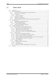
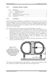
ITER G A0 FDR 1 01-07-13 R1.0Tokamak Building HVAC <strong>and</strong> <strong>Detritiation</strong> SystemsThe HVAC <strong>and</strong> detritiation systems for the tokamak building are composed of two dedicatedheating, ventilation <strong>and</strong> air conditioning systems for the gallery areas (HVAC-I) <strong>and</strong> for thecontainment volume (the tokamak cooling water system vault <strong>and</strong> annex, CVCSs area, NBcell, upper <strong>and</strong> lower pipe chases, <strong>and</strong> vertical pipe shafts) (HVAC-II), <strong>and</strong> variousatmosphere detritiation systems such as the normal vent detritiation system, the st<strong>and</strong>by roomair vent detritiation system, the st<strong>and</strong>by room air detritiation system, <strong>and</strong> the tokamak ventsystem for these areas. As an additional function of the HVACs for the gallery <strong>and</strong> thecontainment volume, local air coolers are incorporated for continuous removal of the heatload from various equipment <strong>and</strong> lighting.Figures <strong>3.1</strong>-2 <strong>and</strong> 3 show the integrated confinement <strong>and</strong> detritiation system configurationsfor the tokamak building. During plasma operation <strong>and</strong> baking, a negative relative pressureof - 1 mbar in the gallery areas is maintained by HVAC-I. Through a small duct the galleryarea is connected with the tokamak pit free volume (~ 5,000 m 3 , leakage rate 10 vol%/d) inbetween the cryostat outer surface <strong>and</strong> the bioshield inner surface. This ensures that airleakage between the crane hall <strong>and</strong> the pit free volume (~ 20 m 3 /h) is always in the directionof the pit.Ducts are installed between the bioshield inner wall <strong>and</strong> the cryostat outer wall enclosing theport openings. This effectively seals off the port area from the pit free-air volume <strong>and</strong>prevents the cross-contamination from one port to another.To avoid condensation of the moisture, which is included in the external air, onto the cryostatsurface, a forced air circulation system with a small rotary air dryer unit (throughput 150m 3 /h) composed of a compressor <strong>and</strong> an internal gas/water heat exchanger is utilized.As schematically shown in Figure <strong>3.1</strong>-2, the port cell pressure is kept at - 2 mbar differentialpressure by continuously extracting air by the normal vent detritiation system to form apressure gradient from the gallery areas (-1 mbar) to the ports. With this confinementconfiguration, it is possible to localise tritium contamination, <strong>and</strong> to eliminate the risk oftritium release to the environment during port maintenance.It is intended to route all tritium-bearing pipes, e.g., vacuum <strong>and</strong> fuelling lines, thatinterconnect the vacuum vessel with the tritium plant, <strong>and</strong> hence cross the gallery areas,inside the floor slabs of the galleries, such that their secondary containment volume is eitherpumped or purged to the tritium plant. This design configuration makes release from theselines into the gallery areas a beyond-design-basis event, <strong>and</strong> avoids the need to haveemergency isolation valves in the gallery areas HVAC system.HVAC-II (Figure <strong>3.1</strong>-3) for the containment volume (volume 51,000 m 3 , air leakage rate 10vol%/d at a room internal pressure of 2 bar(abs)) is not operated during plasma operation <strong>and</strong>baking, <strong>and</strong> a differential room pressure of – 3 mbar is maintained by the normal ventdetritiation system by extracting room air with a flow rate equivalent to the volume airleakage rate.<strong>Plant</strong> Description Document Chapter <strong>3.1</strong> Page 7
ITER G A0 FDR 1 01-07-13 R1.0Figure <strong>3.1</strong>-2Configuration of HVAC Systems<strong>Plant</strong> Description Document Chapter <strong>3.1</strong> Page 8
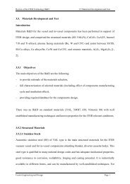
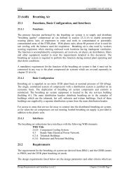
ITER G A0 FDR 1 01-07-13 R1.0a) HVAC- II - Normal operationFresh airHVACSupply UnitsTokamak Containment VolumeSt<strong>and</strong>by Vent<strong>Detritiation</strong>SystemPressure: -3 mbar relativeRecycleAir <strong>Detritiation</strong>DryersVaultCoolersSt<strong>and</strong>byAtmosphere<strong>Detritiation</strong>SystemNormal Vent<strong>Detritiation</strong>SystemExhaustExhaustHVACExhaust Unitsb) HVAC- II - MaintenanceFresh airHVACSupply UnitsTokamak Containment VolumeSt<strong>and</strong>by Vent<strong>Detritiation</strong>SystemPressure: -3 mbar relativeRecycleAir <strong>Detritiation</strong>DryersVaultCoolersSt<strong>and</strong>byAtmosphere<strong>Detritiation</strong>SystemNormal Vent<strong>Detritiation</strong>SystemExhaustExhaustHVACExhaust Unitsc) HVAC- II -Overpressure ContainmentFresh airHVACSupply UnitsTokamak Containment VolumeSt<strong>and</strong>by Vent<strong>Detritiation</strong>SystemRecyclePressure: 0.2 MPa (absolute)decreased to atmospheric in24 h by st<strong>and</strong>by vault coolerAir <strong>Detritiation</strong>DryersVaultCoolersSt<strong>and</strong>byAtmosphere<strong>Detritiation</strong>SystemNormal Vent<strong>Detritiation</strong>SystemExhaustExhaustHVACExhaust UnitsFigure <strong>3.1</strong>-3 Tokamak Building Confinement <strong>and</strong> <strong>Detritiation</strong> SystemConfiguration of HVAC II(TWCS Vault <strong>and</strong> Vault Annex Upper <strong>and</strong> Lower Pipe Chases,Vertical Pipe Shafts, NB Cell)<strong>Plant</strong> Description Document Chapter <strong>3.1</strong> Page 9
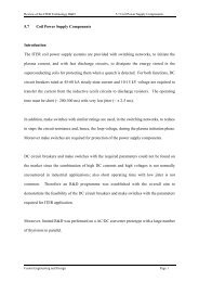
ITER G A0 FDR 1 01-07-13 R1.0d) HVAC- II - Containment Under -3 mbar PressureN 32 GR 105 01-02-26 W 0.1Fresh airHVACSupply UnitsTokamak Containment VolumeSt<strong>and</strong>by Vent<strong>Detritiation</strong>SystemRecyclePressure: -3 mbar relativeAir <strong>Detritiation</strong>DryersVaultCoolersSt<strong>and</strong>byAtmosphere<strong>Detritiation</strong>SystemNormal Vent<strong>Detritiation</strong>SystemExhaustExhaustHVACExhaust Unitse) HVAC- II - Enhanced <strong>Detritiation</strong>Fresh airHVACSupply UnitsTokamak Containment VolumeSt<strong>and</strong>by Vent<strong>Detritiation</strong>SystemRecyclePressure: -3 mbar relativeAir <strong>Detritiation</strong>DryersVaultCoolersSt<strong>and</strong>byAtmosphere<strong>Detritiation</strong>SystemNormal Vent<strong>Detritiation</strong>SystemExhaustExhaustHVACExhaust Unitsf) HVAC- II - Recover MaintenanceFresh airHVACSupply UnitsTokamak Containment VolumeSt<strong>and</strong>by Vent<strong>Detritiation</strong>SystemRecyclePressure: -3 mbar relativeAir <strong>Detritiation</strong>DryersVaultCoolersSt<strong>and</strong>byAtmosphere<strong>Detritiation</strong>SystemNormal Vent<strong>Detritiation</strong>SystemExhaustExhaustHVACExhaust UnitsFigure <strong>3.1</strong>-3 Tokamak Building Confinement <strong>and</strong> <strong>Detritiation</strong> SystemConfiguration HVAC II (continued)(TWCS Vault, Vault Annex, Upper <strong>and</strong> Lower Pipe Chases,Vertical Pipe Shafts, <strong>and</strong> NB Cell)The heat load (plasma operation: 0.8 MW, baking: ~ 1 MW) in the containment volumegenerated by pump motors <strong>and</strong> losses through the thermal insulation around pipes <strong>and</strong>components of the tokamak cooling water system, is continuously removed by thecontainment volume air coolers (cooling capacity 1.2 MW). Moreover, in the case of a large<strong>Plant</strong> Description Document Chapter <strong>3.1</strong> Page 10
ITER G A0 FDR 1 01-07-13 R1.0ex-vessel coolant leak (~ 100 m 3 water), the resulting steam pressure (below 0.2 MPa) isreduced to ambient within 24 h by steam condensation at the containment volume coolers.Tritiated moisture leaking from the tokamak cooling water system is also continuouslyremoved by air detritiation dryers. The condensate of the coolers <strong>and</strong> the air detritiationdryers may include tritium, thus it is sent to the water detritiation system before its rejectionto the environment. <strong>Tritium</strong> permeation into the tokamak cooling water system coolant isestimated to be relatively small, therefore the air detritiation dryers will be installed laterwhen required in the operation programme.In case an ex-vessel leak occurs <strong>and</strong>/or a wet bypass event (bypass between the tokamakcooling water system vault to the vacuum vessel interior via a failed tokamak cooling watersystem loop) is caused as a consequence of an ex-vessel coolant leak, the normal ventdetritiation system is isolated <strong>and</strong> the st<strong>and</strong>by vault cooler (0.2 MW capacity) is started up.When the normal temperature <strong>and</strong> pressure in the containment volume are regained in 24 h,the st<strong>and</strong>by vent detritiation system (throughput 3,000 m 3 /h) <strong>and</strong> the st<strong>and</strong>by atmospheredetritiation system (throughput 4,500 m 3 /h) will be operated to enhance detritiation, whichmay allow early entrance to the vault areas to repair <strong>and</strong>/or replace failed piping <strong>and</strong>components.An emergency water holding sump tank system of 400 m 3 capacity is installed in thebasement room of the tritium building, to collect tritiated water generated (~ 100 m 3 /month)by the operation of these detritiation systems.Another type of wet bypass scenario (opening size < 0.02 m 2 ) due to the failure of a vesselpenetration <strong>and</strong>/or a failure of diagnostic windows (both primary <strong>and</strong> secondaryconfinement), which may occur as a consequence of in-vessel coolant leakage, has beenconsidered. In this case, the tokamak vent system (throughput 150 m 3 /h) connected to thenormal vent detritiation system, is started up within 3 minutes to prevent the internal pressureof the vacuum vessel from exceeding the area room pressure. During this scenario thetokamak vent system receives a stream from the tokamak vessel of high temperature (up to300°C) <strong>and</strong> high humidity (up to 0.1 MPa vapour pressure).In the case of a small-scale dry bypass event (opening size ~ 0.02 m 2 ), which may be causedby a failure of both primary <strong>and</strong> secondary confinement boundary windows attached to adiagnostic or heating system, allowing penetration of both the vacuum vessel <strong>and</strong> the cryostatboundaries, the air is immediately heated by the first wall <strong>and</strong> the volumetric expansion ofthe air results in a back flow of tritium containing air to the port cells. A relatively high levelof leak tight design (in-leakage rate ~ 100 vol %/day) is applied to all port cells, <strong>and</strong> theatmosphere of the port cells is detritiated by a permanent connection to a dedicated normalvent detritiation system.For tokamak maintenance through the vessel ports, the st<strong>and</strong>by atmosphere detritiationsystem is switched to tokamak maintenance mode by connecting it to the tokamak vessel viathe torus vacuum pumping ducts. The closed loop through the st<strong>and</strong>by atmospheredetritiation system <strong>and</strong> tokamak vessel circulates dry air <strong>and</strong> continuously removes tritiumoutgassing from the first wall. The flow rate is adjusted to ~ 2,000 m 3 /h to avoid widedispersion of fine particles of tokamak dust due to turbulent flow in the vessel. Thismaintenance loop is also connected to the normal vent detritiation system, <strong>and</strong> a small flow isextracted from the loop to maintain negative pressure in the tokamak vessel.<strong>Plant</strong> Description Document Chapter <strong>3.1</strong> Page 11
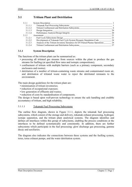
ITER G A0 FDR 1 01-07-13 R1.0The atmosphere detritiation systems, HVACs <strong>and</strong> containment volume air cooler equipmentare located in the tritium building. The condensate of the equipment is sent to the tritiatedwater holding tank systems in the tritium building.<strong>Tritium</strong> Building Confinement <strong>and</strong> <strong>Detritiation</strong> SystemsThe confinement <strong>and</strong> detritiation systems for the tritium building are composed of tritiumprocess equipment (primary barrier), enclosures such as glove boxes (secondary barrier), <strong>and</strong>tritium process rooms (final barrier). The secondary confinement is implemented by theglove box atmosphere detritiation system <strong>and</strong>/or the dry N 2 gas purge to the normal ventdetritiation system. The tritium process rooms are backed up by the tritium building HVACs,the normal vent detritiation system (500 m 3 /h) <strong>and</strong> the st<strong>and</strong>by atmosphere detritiationsystem.Figure <strong>3.1</strong>-4 shows the concept of the confinement <strong>and</strong> detritiation system configuration forthe tritium building. It also shows the interface with the ADS <strong>and</strong> VDS units for the tokamakbuilding. The dotted lines indicate the possibility to connect the vault volume to the S-ADS<strong>and</strong> S-VDS. The HVAC is composed of a white zone HVAC <strong>and</strong> two green zone HVACs,i.e. one for the water detritiation system room <strong>and</strong> tritiated water holding tank rooms, anotherone for other tritium processing subsystems rooms. During normal conditions, the roomatmosphere pressure in the green zone is maintained at - 1 mbar differential by the HVAC.When the room air tritium concentration exceeds a set point, the relevant room isolationvalves in the HVAC are closed, <strong>and</strong> triggers cause the isolation valves connected to thenormal vent detritiation system to open.In the case that large room areas are contaminated simultaneously, the st<strong>and</strong>by ventdetritiation system (3,000 m 3 /h) will be operated with a required flow rate. The st<strong>and</strong>by ventdetritiation system can be switched to three main areas, i.e. the tokamak building gallery area,the containment volume, <strong>and</strong> the tritium building green zone areas. The st<strong>and</strong>by atmospheredetritiation system (4,500 m 3 /h) is operated to enhance decontamination of the contaminatedrooms to ensure early entry to reestablish normal conditions.In addition, the normal vent detritiation system (throughput 500 m 3 /h) receives variousexhaust gases from different sources depending on their operation modes, maintenanceschedule <strong>and</strong> their off-normal conditions. The normal vent detritiation system has a st<strong>and</strong>bycapacity (~ 200 – 300 m 3 /h) to meet such intermittent gas sources.Figure <strong>3.1</strong>-5 shows the concept of an integrated atmosphere detritiation for both the tokamak<strong>and</strong> tritium buildings. The equipment of all atmosphere detritiation systems is located in thetritium building. Figure <strong>3.1</strong>-6 shows an integral configuration of the glove box atmospheredetritiation system (throughput 150 m 3 /h) <strong>and</strong> glove boxes. All glove boxes are purified byre-circulating the atmospheric gas (N 2 ) through the glove box atmosphere detritiation systemduring normal conditions. In case the tritium concentration in one of the glove boxes exceedsa set point (1 mCi/m 3 ) due to a failure of equipment or process piping, other glove boxes areisolated from the glove box atmosphere detritiation system gas circulation loop, <strong>and</strong> the fullglove box atmosphere detritiation system capacity, is dedicated to the contaminated glovebox for enhanced detritiation. Even if the maximum tritium inventory of 100 g in the tritiumstorage bed is instantaneously spilled in a representative glove box (volume 30 m 3 ), 99.9 %<strong>Plant</strong> Description Document Chapter <strong>3.1</strong> Page 12
ITER G A0 FDR 1 01-07-13 R1.0recovery is achieved in a few hours. The resulting tritium permeation into the room throughthe gloves will be less than a few Ci, <strong>and</strong> retained by the normal vent detritiation system.<strong>Plant</strong> Exhaust FacilityUpper Port CellsN-VDS 2Equator Port CellsLower Port CellsS-VDSTokamak BuildingN-VDS 1S-ADS<strong>Tritium</strong> Process EffluentsVacuum Pumping Systems EffluentsFuelling Systems Purge GasGlovebox, Secondary Ernclosure Purge GasTritiated Water Holding Tank Purge GasHVAC-ILocal AirCoolerHVAC-IILocal AirCoolerNon <strong>Tritium</strong> ProcessRoomsTCWS EffluentTVS EffluentRoom Pressure ControlP/FH/CP/FH/CH/CH/FC/CH/FC/CC/CP/FP/FP/FExhaustFresh Air ExhaustFresh Air ExhaustFresh AirP/FH/FPre Filter C/C Cooling Coil Butterfly valveHEPA FilterH/CHeating Coil Glove valve (Normal Open)Glove valve (Normal Close)Process line (Normal Operation)Process line (St<strong>and</strong>by)Figure <strong>3.1</strong>-4Concept of Confinement <strong>and</strong> <strong>Detritiation</strong> System Configurationfor the <strong>Tritium</strong> Building<strong>Plant</strong> Description Document Chapter <strong>3.1</strong> Page 13
ITER G A0 FDR 1 01-07-13 R1.0to <strong>Plant</strong> Exhaust FacilityNormal Vent DetritationSystemsSt<strong>and</strong>by Vent DetritationSystems<strong>Tritium</strong>Building<strong>Tritium</strong> ProcessingRoomsGlovebox AtmosphereDetritation SystemSecondary EnclosuresSecondary EnclosuresFuelling <strong>and</strong>Pumping Systems<strong>Tritium</strong> ProcessingSubsystemsTokamak Vent SystemSt<strong>and</strong>by AtmosphereDetritation SystemTokamakBuildingGalleries (65,000 m 3 )Containment Volume(46,000 m 3 )Port CellsSecondary EnclosuresTokamak CoolingWater SystemVacuumVesselFuel Injection <strong>and</strong>Pumping SystemsPit Free VolumeRotary DryerContainment VolumeAir CoolersDiverterDrying SystemSafety Class SystemsNormal OperationMaintenance <strong>and</strong> Off-Normal OperationFigure <strong>3.1</strong>-5Integrated Atmosphere <strong>Detritiation</strong> System Configuration for theTokamak <strong>and</strong> the <strong>Tritium</strong> Buildings<strong>Plant</strong> Description Document Chapter <strong>3.1</strong> Page 14
ITER G A0 FDR 1 01-07-13 R1.0GB NGB NGB N-1GB N-1TMGB XTMGB XGB 3GB 3GB 2GB 2GB 1GB 1GDSGDSN-VDSExhaustN-VDSExhaustDry N 2 Gas PurgeDry N 2 Gas PurgeNormal operating mode <strong>Detritiation</strong> Mode at <strong>Tritium</strong>Spill EventTMFigure <strong>3.1</strong>-6 Integral System Configuration of the Glove Box Atmosphere <strong>Detritiation</strong>System, Glove Boxes <strong>and</strong> the Normal Vent <strong>Detritiation</strong> SystemTritiated water produced by the operation of these detritiation systems is collected by anintermediate measuring tank <strong>and</strong> then sent to the tritiated water holding tank systems aftermeasurement of the tritium concentration levels. Condensate of the HVAC <strong>and</strong> local aircoolers is sent to the tritiated water holding tanks in a similar manner.Hot Cell <strong>and</strong> Radwaste Building Confinement <strong>and</strong> <strong>Detritiation</strong> SystemsThe confinement <strong>and</strong> detritiation systems for the hot cell <strong>and</strong> the radwaste buildings arecomposed of their HVACs, a hot cell red zone detritiation system, <strong>and</strong> the vent detritiationsystem. Activated dust <strong>and</strong> decay heat from in-vessel components introduced in the red zoneare separately removed by local filters <strong>and</strong> local air coolers installed in a green zone in thehot cell. Figure <strong>3.1</strong>-7 shows the configuration of an integrated confinement <strong>and</strong> detritiationsystem for these buildings. The atmospheric pressure of the hot cell green zone is maintainedat a differential of - 1 mbar by the HVAC during normal conditions, <strong>and</strong> the pressures in theamber <strong>and</strong> the red zone are maintained at differentials of - 2 mbar <strong>and</strong> - 3 mbar, respectivelyby the hot cell vent detritiation system. The hot cell vent detritiation system capacity (700m 3 /h) includes st<strong>and</strong>by capacity for an emergency tritium confinement for any green zone<strong>Plant</strong> Description Document Chapter <strong>3.1</strong> Page 15
ITER G A0 FDR 1 01-07-13 R1.0rooms in the hot cell <strong>and</strong> the radwaste buildings, where the relevant HVAC isolation valvesare closed.Radwaste BuildingEnhancedDetritation FlowRed Zone 1-04Red Zone 1-11Red Zone 1-12HC-ADSAmber ZoneRoomsDifferentialPressure ControlFlowHC-VDSExhaustRooms in 4th FloorRooms in 3rd FloorRooms in 2nd FloorRooms in 1st FloorRed zone total room volume: 8,400 m 3Amber zone total room volume: 2,700 m 3BlowerSolid lines: Normal operationDashed line: St<strong>and</strong>byP/FH/FH/CC/CP/FP/FH/FH/CC/CP/FP/FH/FH/CC/CP/FBlowerExhaust Fresh Air Exhaust Fresh AirExhaustFresh AirH/C : Heating CoilC/C: Cooling CoilP/F: Pre FilterH/F: HEPA Filter: Isolation ValveFigure <strong>3.1</strong>-7Hot Cell <strong>and</strong> Radwaste Buildings - Confinement <strong>and</strong><strong>Detritiation</strong> System ConfigurationThe hot cell atmosphere detritiation system (capacity 4,500 m 3 /h) is manifolded to all redzone rooms to control the air flow rate required in each room depending on their operationstates. The achievable room air HTO concentration during occupancy by the maximumnumber of divertor cassettes (estimated tritium outgassing rate ~ 18 Ci/h) is 500 DAC(Derived Air Concentration: unprotected exposure to 1 DAC = 10 µSv/h), or 1.6 x10 8 Bq/m 3 .The reduction rate of the HTO concentration after removal of divertor cassettes or othertritium source terms from the room depends on the decontamination characteristics of thewall surface, <strong>and</strong> based on recent R&D results, the tritium concentration can be lowered to 1DAC within approximately 5 days using the atmosphere detritiation system at full capacity.Saturated molecular sieve beds in these detritiation systems are regenerated by a hot celldedicated regeneration system. The recovered condensate from the regeneration system <strong>and</strong>the HVAC is sent to the tritiated water holding tanks system located in the tritium building ina manner similar to that for the tritium plant systems.In order to reduce the generation rate of tritiated water from hot cell operation, minimizationof the leakage rate in the building walls, doors <strong>and</strong> other penetrations is being investigated.The tentative estimate of water generation based on the present design parameters (roomvolume, leak tightness, humidity <strong>and</strong> temperatures) is ~ 0.3 m 3 /d.<strong>Plant</strong> Description Document Chapter <strong>3.1</strong> Page 16
ITER G A0 FDR 1 01-07-13 R1.0Water <strong>Detritiation</strong> SystemDuring operation of ITER, tritiated water will be produced in various systems. The expectedsources are:(a) condensate generated from the normal operation of various atmosphere detritiationsystems <strong>and</strong> HVACs,(b) tritium process component maintenance,(c) condensate from the air coolers in the containment volume (designed to limitoverpressures from an ex-vessel coolant leak),(d) air detritiation dryers in the containment volume,(e) the tokamak cooling water system maintenance drain <strong>and</strong> the tokamak cooling watersystem vent gas condensate,(f) in-vessel component maintenance drain collected in the hot cell, <strong>and</strong>(g) condensate from the st<strong>and</strong>by vent detritiation system <strong>and</strong> the st<strong>and</strong>by atmospheredetritiation system operated during tritium contamination accidents.The source water (a) - (d) will be processed by the water detritiation system to minimizetritium-bearing waste water to be rejected to the environment, whereas the water (e) <strong>and</strong> (f) isrecycled to the tokamak cooling water system. The water (g) will be stored in the emergencyholding sump tanks.The source water will be stored in the holding tank system with the following levelclassification:• H Level > 100 Ci/kg;• M Level 10 -3 Ci/kg – 100 Ci/kg;• L Level 1.6 x 10 -6 Ci/kg - 10 -3 Ci/kg;• LL Level < 1.6 x 10 -6 Ci/kg for direct release after assaying;• emergency holding sump tanks: total capacity 400 m 3The high (H) level <strong>and</strong> the medium (M) level tanks receive condensate from the atmospheredetritiation systems <strong>and</strong> the local air coolers in the hot cell building <strong>and</strong> the tritium plantbuilding, <strong>and</strong> the process blow-down water of the water detritiation system at maintenance.In case of an event leading to a large amount of tritium contamination, condensate producedby the st<strong>and</strong>by atmosphere detritiation system <strong>and</strong> the st<strong>and</strong>by vent detritiation system will bestored in either the H level or the emergency holding sump tanks. The low (L) level tanksreceive drainage from tritium process equipment during its maintenance. The low low (LL)level tank receives water generated in the HVACs, <strong>and</strong> the water can be directly rejected tothe environment after assaying the tritium concentration.Figure <strong>3.1</strong>-8 shows the outline flow diagram for the water detritiation system, but does notshow the LL level or emergency holding sump tanks. Tritiated water sent from the holdingtank system is purified by the front-end processing system composed of demineralizer <strong>and</strong>charcoal beds to remove hazardous ions <strong>and</strong> organic species to the catalytic exchange process<strong>and</strong> electrolysis. The purified water (tritium concentration < 10 Ci/kg) is then fed (~ 20 kg/h)either to the catalytic exchange towers (tritium feed concentration < ~ 10 Ci/kg) or to theelectrolysers (tritium feed concentration ~ 100 – 500 Ci/kg). Pure water is fed (~ 20 kg/h) tothe top of the catalytic exchange tower.<strong>Plant</strong> Description Document Chapter <strong>3.1</strong> Page 17
ITER G A0 FDR 1 01-07-13 R1.0Figure <strong>3.1</strong>-8 Outline Flow Diagram for the Water <strong>Detritiation</strong> System<strong>Plant</strong> Description Document Chapter <strong>3.1</strong> Page 18
ITER G A0 FDR 1 01-07-13 R1.0The catalytic exchange towers are composed of hydrophobic catalyst-packed sections <strong>and</strong> ahydrophilic-packing section (sieve tray). The isotopic exchange reactions taking place in eachsection are:HT (G) + H 2 O (V) = H 2 (G) + HTO (V): Hydrophobic catalyst sectionHTO (V) + H 2 O (L) = H 2 O (V) + HTO (L): Hydrophilic packing sectionwhere, G, V <strong>and</strong> L in these equilibrium reactions mean gas, vapour <strong>and</strong> liquid phases,respectively.Through these counter-current catalytic exchange reactions, tritium (T) is enriched in thewater which is flowing to the bottom of the towers, <strong>and</strong> hydrogen gas which containsvirtually no tritium is flowing to the top of the tower. The enriched water is then dissociatedinto hydrogen gas H 2 (T) <strong>and</strong> O 2 gas by the electrolysers. The H 2 (T) is returned to the bottomof the tower, <strong>and</strong> a part of the hydrogen gas stream (280 mol/h) is sent to the hydrogenisotope separation system to recover tritium via a membrane permeator system. Thehydrogen stream from the top of the tower is rejected to the environment through the flamearrester. The O 2 stream from the electrolysers is sent to the normal vent detritiation systemvia the O 2 gas processing system composed of molecular sieve dryers.The membrane permeator <strong>and</strong> molecular sieve dryer, which are operated at elevatedtemperature, <strong>and</strong> electrolysers, are placed in a secondary enclosure to avoid tritiumleakage/permeation to the room. The atmosphere (dry N 2 gas) of the secondary enclosure issent to the normal vent detritiation system with a small flow rate.The water detritiation system can be operated with high availability (more than 300days/year). Demineralizers <strong>and</strong> charcoal beds require frequent replacement (every twoyears), <strong>and</strong> the electrolyser, based on solid polymer electrodes, may need electrodereplacement once per year due to expected deterioration caused by β-ray exposure fromtritium-enriched water. A detailed maintenance procedure, which can h<strong>and</strong>le componentscontaminated by highly concentrated tritiated water, has been developed <strong>and</strong> reflected in thewater detritiation system design.<strong>Plant</strong> Description Document Chapter <strong>3.1</strong> Page 19
ITER G A0 FDR 1 01-07-13 R1.0Developments in laser Raman spectroscopy include the application of an external resonatorwhich enables quantitative analysis of hydrogen isotope mixtures to be carried out. Thistechnique is proposed for periodic calibration of the on-line pressure <strong>and</strong> temperaturemeasurement techniques used for the product quality control of the isotope separation system.The layout of tritium plant systems within the building has been reviewed to ensure that allrequirements for space, access, <strong>and</strong> environmental conditions are met. The effect of theequipment on the building design such as mechanical loads <strong>and</strong> heat dissipationrequirements, have been taken into account. Access routes for the introduction of deferredequipment <strong>and</strong> for the replacement <strong>and</strong> removal of components during maintenance <strong>and</strong>routine operations, such as the import of tritium transport containers, have been checked. Thedesign of the building is conventional, <strong>and</strong> consistent with the practice followed at existingtritium laboratories, upgraded where necessary to provide additional features such asshielding capability.The distributed control system with PLCs <strong>and</strong> a hardwired system for alarm <strong>and</strong> emergencyshut-down developed for the ITER tritium plant (Figure <strong>3.1</strong>-9) is consistent with systemscurrently in operation in tritium laboratories. It is to be expected that advances in system <strong>and</strong>hardware design will occur prior to the implementation of the ITER tritium plant <strong>and</strong> thesewill be reviewed <strong>and</strong> adopted where appropriate.Figure <strong>3.1</strong>-9 <strong>Tritium</strong> <strong>Plant</strong> Automated Control System ConfigurationDWS: Display Work Station, EWS: Engineers’ Work StationOLM: Optical Link Module, DPU: Distributed Process Unit<strong>Plant</strong> Description Document Chapter <strong>3.1</strong> Page 23
ITER G A0 FDR 1 01-07-13 R1.0<strong>3.1</strong>.2.2 Development of Tokamak Fuel Cycle System Dynamic Simulation CodeThe fuel cycle dynamic simulation code CFTSIM 1 was developed during the ITER EDAthrough a design task. This code provides an integrated dynamic simulation of the ITER fuelcycle. It presents the user with a graphical representation of the ITER tritium plant. The codemodels the ITER fuel cycle pathways for deuterium <strong>and</strong> tritium, including the followingsystem models, in varying degrees of detail.(i)(ii)(iii)(iv)(v)(vi)(vii)(viii)Fuelling System Model (Storage <strong>and</strong> Delivery System Model);Codeposited Layer Dust Model;First Wall Model;Tokamak Model;Tokamak Chamber Model;Tokamak Exhaust Processing System Model;Hydrogen Isotope Separation System Models;Neutral Beam Injectors Model.<strong>3.1</strong>.2.3 Analysis of the <strong>Tritium</strong> Inventory Dynamics for DT Pulsed Plasma OperationsFor the purpose of design improvement in the interfaces between the SDS, TEP <strong>and</strong> ISS, aseries of preliminary studies of the tritium inventory dynamics were implemented by usingthe CFTSIM code. The following cases of DT plasma operation were selected as beingrepresentative of the plasma operation:(i) Short DT pulse operation (450 s burn, 1,350 s dwell) with 200 Pam 3 /s total fuellingflow rate (deep fuelling 50 Pam 3 s -1 T 2 , shallow fuelling 100 Pam 3 /s DT + 44.5 Pam 3 /sD 2 + 5.5 Pam 3 /s T 2 ),(ii) Long DT pulse operation (3,000 s burn, 9,000 s dwell) with 200 Pam 3 /s total fuellingflow rate (deep fuelling 50 Pam 3 /s T 2 , shallow fuelling 100 Pam 3 /s DT + 44.5 Pam 3 /sD 2 + 5.5 Pam 3 /s T 2 ). Table 1-7 summarizes the input parameters selected for theserepresentative cases.Figures <strong>3.1</strong>-10 (a) <strong>and</strong> (b) show the results of the tritium inventory dynamics over fiverepetitive pulses. In the present preliminary analysis, the entire column cascade of the ISSwas started up with pure D 2 gas immediately after receiving the feed stream (tokamakexhaust stream) via the front-end permeator. The time to establish steady-state concentrationprofiles of the 6 possible hydrogen isotope mixtures (permutations of H, D <strong>and</strong> T) incascade, will require a distillation time of 1,000 s or more.The total tritium inventory shown in these figures does not include the following inventoryelements:(i) tritiated impurities trapped in the torus cryo-pump during the five pulses,(ii) tritium trapped by the plasma-facing components, <strong>and</strong> co-deposited material in thevacuum vessel.(iii) tritiated impurities processing in the tokamak exhaust processing unit.1 A. Busigin <strong>and</strong> P. Gierszewski, “CFTSIM-ITER dynamic fuel cycle model”, Fus. Eng. & Design 39-40(1999), p 909<strong>Plant</strong> Description Document Chapter <strong>3.1</strong> Page 24
ITER G A0 FDR 1 01-07-13 R1.0Figure <strong>3.1</strong>-10 (a)<strong>Tritium</strong> Inventory Dynamics in the Fuel Cycle System(for Short DT Pulses)<strong>Plant</strong> Description Document Chapter <strong>3.1</strong> Page 25
ITER G A0 FDR 1 01-07-13 R1.0Figure <strong>3.1</strong>-10 (b)<strong>Tritium</strong> Inventory Dynamics in the Fuel Cycle Systems(for Long DT Pulses)<strong>Plant</strong> Description Document Chapter <strong>3.1</strong> Page 26
ITER G A0 FDR 1 01-07-13 R1.0<strong>3.1</strong>.2.4 <strong>Tritium</strong> Confinement <strong>and</strong> <strong>Detritiation</strong> SubsystemsHVACBecause of their functional requirements during off-normal events in the tokamak, tritium,hot cell <strong>and</strong> radwaste buildings, the HVAC systems are safety classified systems thereforethere are 2 emergency room isolation dampers (high leak tightness butterfly valves) in seriesbacked up by emergency power <strong>and</strong>/or emergency compressed gas (N 2 ). However, allHVAC equipment such as blowers, heating <strong>and</strong> cooling coils, pre-filters <strong>and</strong> HEPA (highefficiency particulate) filters, emergency isolation dampers, <strong>and</strong> fire isolation dampers areindustrial items, <strong>and</strong> no specific R&D has been required for their use in ITER.Atmosphere <strong>Detritiation</strong> SystemsAs described in <strong>3.1</strong>.1.2, different atmosphere detritiation systems are employed to meet theconfinement <strong>and</strong> detritiation requirements at different operation states of the tokamak,tritium, hot cell <strong>and</strong> radwaste buildings. The process configurations of these atmospheredetritiation systems are different, based on the confinement strategy <strong>and</strong> safety requirements(off-normal event scenarios).Figure <strong>3.1</strong>-11 shows a conceptual process flow diagram of the st<strong>and</strong>by atmospheredetritiation system, which is a typical safety classified atmosphere detritiation systemsimilar to the normal vent detritiation system, st<strong>and</strong>by vent detritiation system, hot cellatmosphere detritiation system <strong>and</strong> the hot cell vent detritiation system. The st<strong>and</strong>byatmosphere detritiation system is designed to process various tritiated source gases containinghigh levels of elemental tritium, tritiated hydrocarbons, <strong>and</strong> saturated moisture. The processconfiguration is characterised by the three loops described below.a) Recombiner loop composed of inlet filter (F-1), inlet blower battery (BL1-A/B/C: 50%capacity/each blower; one blower is redundant), two stage recombiners (Rec-L, Rec-H),two stage recuperative heat exchangers (HX-1, HX-2), one stage electric heater (EH-1),one stage condenser (CX-1), <strong>and</strong> one-stage molecular sieve dryer bed battery (DX-A/B/C). Elemental tritium included in the source gas/air is catalytically converted(conversion factor > 10 4 ) into tritiated water molecules by the first stage recombiner(operating temperature 150°C), <strong>and</strong> tritiated organic species are oxidised (conversionfactor > 10 3 ) to tritiated water molecules <strong>and</strong> CO 2 by the second stage recombiner(operating temperature 500°C). The converted tritiated water molecules are adsorbed bythe molecular sieve dryer bed. Thus, overall tritium permeation through vessel walls <strong>and</strong>pipe lines in the recombiner loop can be minimised by the two-stage recombinerconfiguration. This configuration was selected as an essential design feature to processtritiated source gases containing elemental tritium <strong>and</strong> organic tritium. The glove boxatmosphere detritiation system process uses only a one stage recombiner (operatingtemperature 150°C) because the expected tritiated species in the glove box atmosphereare elemental tritium <strong>and</strong> tritiated moisture (HTO).<strong>Plant</strong> Description Document Chapter <strong>3.1</strong> Page 27
ITER G A0 FDR 1 01-07-13 R1.0Figure <strong>3.1</strong>-11 Conceptual Process Flow Diagram of the St<strong>and</strong>by Atmosphere<strong>Detritiation</strong> System<strong>Plant</strong> Description Document Chapter <strong>3.1</strong> Page 28
ITER G A0 FDR 1 01-07-13 R1.0(b) Molecular sieve dryer regeneration loop composed of regeneration gas heater (EH-2),dryer bed cross-over valve headers, one-stage condenser (CX-2), mist separator (Mis-2),filter (F-2) <strong>and</strong> blower battery (BL2-A/B). Tritiated water produced in the recombinerloops <strong>and</strong>/or included in the source gas/air is adsorbed by the dryer bed. When thedecontamination factor (DF) defined by the tritium concentration ratio between inlet <strong>and</strong>outlet streams around the dryer is > 100 (design value 10 2 – 10 4 ), the saturated dryer bedis then switched to the regeneration mode.(c) Direct condensing loop composed of a one-stage condenser (CX-3) <strong>and</strong> mist separator(Mist-3). In case humidity in the source gas/air is very high or saturated, this bypass loopis started for direct condensing of the moisture, <strong>and</strong> the recombiner loop is isolated untilthe room moisture level is reduced to an acceptable level for the st<strong>and</strong>by atmospheredetritiation system dryer bed battery capacity.The use of the direct condensing loop is an important design feature which results in a largereduction of water load on the molecular sieve dryer regeneration loop.All atmosphere detritiation systems utilise proven technology <strong>and</strong> components such ascanned type blowers, recuperative gas/gas heat exchangers, gas/water heat exchangers,electrical gas heaters, catalytic recombiners <strong>and</strong> molecular sieve dryer beds.The design value of the detritiation factor of these atmosphere detritiation systems (glove boxatmosphere detritiation system > 10 2 ; st<strong>and</strong>by atmosphere detritiation system > 10 3 ; normalvent detritiation system, st<strong>and</strong>by vent detritiation system > 10 4 ) has been well proven in theexisting tritium facilities, <strong>and</strong> no further R&D is required.Common Dryer Regeneration SystemIt is expected that the usage of dryer regeneration systems, which is required for allatmosphere detritiation systems, will be very low for the st<strong>and</strong>by detritiation systems (S-VDS, S-ADS). To maximize the effective usage of the dryer regeneration system, a commondryer regeneration system was employed for ITER instead of a distributed regenerationsystem in each detritiation system. A similar design (use of common regeneration system)was applied to the atmosphere detritiation systems located in the hot cell building.Water <strong>Detritiation</strong> SystemThe water detritiation system selected for ITER is based on the existing plant technologyusing catalytic exchange towers <strong>and</strong> electrolysers, which has been operated over 13 years in aJapanese fission reactor. The advantages of the plant technology are compact size due to itsvery high separation efficiency, no production of tritium-bearing waste water due to acomplete decomposition of the water into molecular hydrogen <strong>and</strong> oxygen, <strong>and</strong> operationflexibility over a wide range of tritium concentration (1 mCi/kg – 500 Ci/kg) by thecombination of a tritium-scavenging catalytic exchange process with tritiated waterelectrolysis. The long-term operation of the existing plant has indicated that tritium levels inthe exhaust hydrogen stream can be directly rejected to the environment with suitable airdilution to meet the deflagration limit (1 vol% in air).<strong>Plant</strong> Description Document Chapter <strong>3.1</strong> Page 29