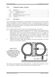
3.1 Tritium Plant and Detritiation - General Atomics Fusion Group
3.1 Tritium Plant and Detritiation - General Atomics Fusion Group
3.1 Tritium Plant and Detritiation - General Atomics Fusion Group
- No tags were found...

You also want an ePaper? Increase the reach of your titles
YUMPU automatically turns print PDFs into web optimized ePapers that Google loves.
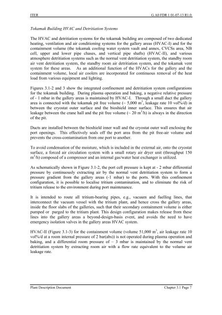
ITER G A0 FDR 1 01-07-13 R1.0Tokamak Building HVAC <strong>and</strong> <strong>Detritiation</strong> SystemsThe HVAC <strong>and</strong> detritiation systems for the tokamak building are composed of two dedicatedheating, ventilation <strong>and</strong> air conditioning systems for the gallery areas (HVAC-I) <strong>and</strong> for thecontainment volume (the tokamak cooling water system vault <strong>and</strong> annex, CVCSs area, NBcell, upper <strong>and</strong> lower pipe chases, <strong>and</strong> vertical pipe shafts) (HVAC-II), <strong>and</strong> variousatmosphere detritiation systems such as the normal vent detritiation system, the st<strong>and</strong>by roomair vent detritiation system, the st<strong>and</strong>by room air detritiation system, <strong>and</strong> the tokamak ventsystem for these areas. As an additional function of the HVACs for the gallery <strong>and</strong> thecontainment volume, local air coolers are incorporated for continuous removal of the heatload from various equipment <strong>and</strong> lighting.Figures <strong>3.1</strong>-2 <strong>and</strong> 3 show the integrated confinement <strong>and</strong> detritiation system configurationsfor the tokamak building. During plasma operation <strong>and</strong> baking, a negative relative pressureof - 1 mbar in the gallery areas is maintained by HVAC-I. Through a small duct the galleryarea is connected with the tokamak pit free volume (~ 5,000 m 3 , leakage rate 10 vol%/d) inbetween the cryostat outer surface <strong>and</strong> the bioshield inner surface. This ensures that airleakage between the crane hall <strong>and</strong> the pit free volume (~ 20 m 3 /h) is always in the directionof the pit.Ducts are installed between the bioshield inner wall <strong>and</strong> the cryostat outer wall enclosing theport openings. This effectively seals off the port area from the pit free-air volume <strong>and</strong>prevents the cross-contamination from one port to another.To avoid condensation of the moisture, which is included in the external air, onto the cryostatsurface, a forced air circulation system with a small rotary air dryer unit (throughput 150m 3 /h) composed of a compressor <strong>and</strong> an internal gas/water heat exchanger is utilized.As schematically shown in Figure <strong>3.1</strong>-2, the port cell pressure is kept at - 2 mbar differentialpressure by continuously extracting air by the normal vent detritiation system to form apressure gradient from the gallery areas (-1 mbar) to the ports. With this confinementconfiguration, it is possible to localise tritium contamination, <strong>and</strong> to eliminate the risk oftritium release to the environment during port maintenance.It is intended to route all tritium-bearing pipes, e.g., vacuum <strong>and</strong> fuelling lines, thatinterconnect the vacuum vessel with the tritium plant, <strong>and</strong> hence cross the gallery areas,inside the floor slabs of the galleries, such that their secondary containment volume is eitherpumped or purged to the tritium plant. This design configuration makes release from theselines into the gallery areas a beyond-design-basis event, <strong>and</strong> avoids the need to haveemergency isolation valves in the gallery areas HVAC system.HVAC-II (Figure <strong>3.1</strong>-3) for the containment volume (volume 51,000 m 3 , air leakage rate 10vol%/d at a room internal pressure of 2 bar(abs)) is not operated during plasma operation <strong>and</strong>baking, <strong>and</strong> a differential room pressure of – 3 mbar is maintained by the normal ventdetritiation system by extracting room air with a flow rate equivalent to the volume airleakage rate.<strong>Plant</strong> Description Document Chapter <strong>3.1</strong> Page 7