3.1 Tritium Plant and Detritiation - General Atomics Fusion Group
3.1 Tritium Plant and Detritiation - General Atomics Fusion Group
3.1 Tritium Plant and Detritiation - General Atomics Fusion Group
- No tags were found...

Create successful ePaper yourself
Turn your PDF publications into a flip-book with our unique Google optimized e-Paper software.
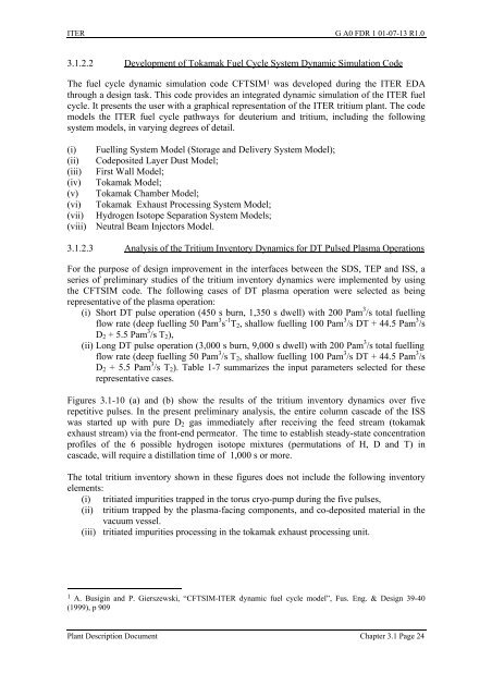
ITER G A0 FDR 1 01-07-13 R1.0<strong>3.1</strong>.2.2 Development of Tokamak Fuel Cycle System Dynamic Simulation CodeThe fuel cycle dynamic simulation code CFTSIM 1 was developed during the ITER EDAthrough a design task. This code provides an integrated dynamic simulation of the ITER fuelcycle. It presents the user with a graphical representation of the ITER tritium plant. The codemodels the ITER fuel cycle pathways for deuterium <strong>and</strong> tritium, including the followingsystem models, in varying degrees of detail.(i)(ii)(iii)(iv)(v)(vi)(vii)(viii)Fuelling System Model (Storage <strong>and</strong> Delivery System Model);Codeposited Layer Dust Model;First Wall Model;Tokamak Model;Tokamak Chamber Model;Tokamak Exhaust Processing System Model;Hydrogen Isotope Separation System Models;Neutral Beam Injectors Model.<strong>3.1</strong>.2.3 Analysis of the <strong>Tritium</strong> Inventory Dynamics for DT Pulsed Plasma OperationsFor the purpose of design improvement in the interfaces between the SDS, TEP <strong>and</strong> ISS, aseries of preliminary studies of the tritium inventory dynamics were implemented by usingthe CFTSIM code. The following cases of DT plasma operation were selected as beingrepresentative of the plasma operation:(i) Short DT pulse operation (450 s burn, 1,350 s dwell) with 200 Pam 3 /s total fuellingflow rate (deep fuelling 50 Pam 3 s -1 T 2 , shallow fuelling 100 Pam 3 /s DT + 44.5 Pam 3 /sD 2 + 5.5 Pam 3 /s T 2 ),(ii) Long DT pulse operation (3,000 s burn, 9,000 s dwell) with 200 Pam 3 /s total fuellingflow rate (deep fuelling 50 Pam 3 /s T 2 , shallow fuelling 100 Pam 3 /s DT + 44.5 Pam 3 /sD 2 + 5.5 Pam 3 /s T 2 ). Table 1-7 summarizes the input parameters selected for theserepresentative cases.Figures <strong>3.1</strong>-10 (a) <strong>and</strong> (b) show the results of the tritium inventory dynamics over fiverepetitive pulses. In the present preliminary analysis, the entire column cascade of the ISSwas started up with pure D 2 gas immediately after receiving the feed stream (tokamakexhaust stream) via the front-end permeator. The time to establish steady-state concentrationprofiles of the 6 possible hydrogen isotope mixtures (permutations of H, D <strong>and</strong> T) incascade, will require a distillation time of 1,000 s or more.The total tritium inventory shown in these figures does not include the following inventoryelements:(i) tritiated impurities trapped in the torus cryo-pump during the five pulses,(ii) tritium trapped by the plasma-facing components, <strong>and</strong> co-deposited material in thevacuum vessel.(iii) tritiated impurities processing in the tokamak exhaust processing unit.1 A. Busigin <strong>and</strong> P. Gierszewski, “CFTSIM-ITER dynamic fuel cycle model”, Fus. Eng. & Design 39-40(1999), p 909<strong>Plant</strong> Description Document Chapter <strong>3.1</strong> Page 24